


 English (pdf)
 Article in xml format
 Article references
 Send this article by e-mail
 Cited by SciELO
  Cited by Google
  Similars in
SciELO
Similars in
SciELO  Similars in Google
 Permalink
1. Introduction
The main function of the urban drainage infrastructure consists of the channeling of surface runoff into the storm sewer pipe network until its eventual discharge into natural bodies of water [1]. The early capture of rainwater prevents rain flooding that generates risk for pedestrians and vehicles, damage to homes and public spaces and the deterioration of the urban economy. The reduction of this risk is possible through the rational distribution of grate inlets on urban streets, whose geometry is particular to each locality or city (this is the case in Colombia).
Recently, urban drainage has been understood as the interaction of three stages that comprise two approaches [1]: the first corresponds to the rain-runoff transformation (hydrological approach), the second is the way this runoff is captured through grate inlets (hydraulic approach) and the third is the transit of the storm water through the sewer pipe network and its hydraulic capacity (hydraulic approach). The first and third approaches involve components called major and minor drainage systems, respectively, and the grate inlets provide interaction between these two systems. The two systems make up the integrated drainage system, also known as the dual drainage system [2]. Usually, the major drainage system is considered to be a two-dimensional hydrodynamic domain (2D) due to the complex geometric irregularity of urban roads while the minor drainage system is considered to be a one-dimensional hydrodynamic domain (1D). Studies using dual drainage models are carried out in a hydraulics laboratory [3,4] or in urban basins [5-8].
The setup of a dual drainage system requires a large amount of information such as the topography of the urban surface (roads, roofs and green areas), the detailed geometry of the sewerage network, the spatial and temporal definition of rainfall and a powerful calculation tool for calculating its solution. In addition, it requires the definition of functions that represent the process of drainage toward the grate inlet, which vary significantly in each city. All these requirements make this kind of modelling difficult and in need of a high budget.
The traditional practice of urban drainage has focused on the analysis of the minor system. This assumes that all the runoff generated enters the sewerage network, when in reality part of it does not, which can lead to possible flooding. A better approach is to suppose a one-dimensional flow over the surface and to estimate the inlet flow with formulations used in other countries whose criteria differ in design from the local methodologies that have important conceptual and engineering inaccuracies.
National and local manuals [9,10] in the design and operation of storm sewer systems do not consider the two-dimensional surface flow nor the inlet functions of grates for the particular conditions of a city. This causes the urban drainage system to suffer from a lack of integration. In addition, the manuals reduce the design criteria to simply rainwater collection in the piping system and to overflow along the edges of roads. This design criteria must be complemented with safety criteria for pedestrians and vehicles and a definition of the economic functions of damages generated by urban floods [11].
Considering the above, this study analyzes the storm runoff on an urban street section using a surface drainage model by means of a two-dimensional hydrodynamic model, outlined in Section 2. Section 3 describes the configuration and sensitivity analysis of the different variables and the definition of the flow inputs and outputs. In Section 4, different flood and hazard response scenarios are described and analyzed to obtain the risk areas and the proposed location of grate inlets on this particular road. This is carried out using a basic equilibrium criterion. Sections 5 and 6 present the conclusions of the study and the references cited, respectively.
2. Framework
2.1. Urban surface drainage model
The urban surface drainage system proposes a solution to the management of rainwater that precipitates in populated cities or urban centers. This system only considers the processes that occur on the surface and assumes the hydraulic efficiency of sewer pipe networks.
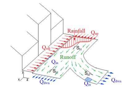
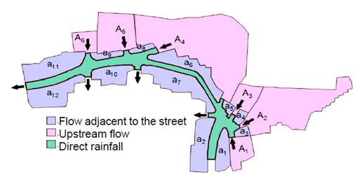
The processes of urban surface drainage are schematized in Fig. 1. It shows the mass inputs into the surface model (in red) which are: the inflow of adjacent homes (Q adj ) due to precipitation on the contiguous roofs (preferably expressed as unit flow or flow per unit length), the inlet flow upstream (Q up ) and the flow resulting from direct precipitation on the street (R). The mass outputs of the surface model (in blue) are the inlet flow into the grate inlets (Q cap ) and the output flow rate downstream (Q dwn ), which is not captured by the grate inlets. The system shows the transit of surface runoff (E) on urban roads (in green). In the mass balance, evaporation and interception components are omitted due to the high intensity of rainfall and the short duration of extreme storms. Infiltration can be considered in the inflow of adjacent houses using any rain-runoff transformation method defined previously.
The two-dimensional hydrodynamic model Iber is used to solve the urban surface drainage model. It is commonly used to model the flows of rivers, estuaries and urban environments. An urban street section was analyzed, and combinations of mass inlets and outflows through the grate inlets were defined. The results of the modeling are used to define the preferential flow and pedestrian risk areas.
2.2. Iber hydrodynamic model
Iber is a two-dimensional mathematical model for simulating the flow of rivers and estuaries. It was developed by the Water and Environmental Engineering Group, GEAMA (University of La Coruña), Mathematical Engineering Group (University of Santiago de Compostela), Flumen Institute (Polytechnic University of Catalonia), International Center for Numerical Methods in Engineering, and promoted by the Center for Hydrographic Studies at CEDEX [12]. Iber is a free-use model that can be downloaded from the website www.iberaula.es.
Iber solves complete two-dimensional Saint Venant equations and incorporates the effects of turbulence and surface friction from wind from a numerical model of finite volumes [12]. Eqs. (1) and (2) represent the conservation of mass and momentum (2D), respectively.
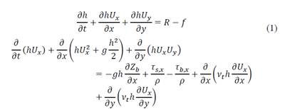
Where h is the depth, U x and U y are the horizontal velocities averaged in the depth, g is the acceleration of gravity, ρ is the density of water, Z b is the bottom elevation, τ s is the friction on the free surface produced by wind, τ b is friction of the bottom and ν t is the turbulent viscosity. The mass balance is complemented by rainfall intensity (R) and infiltration rate (f).
3. Methodology
3.1. Case study: road section
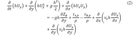
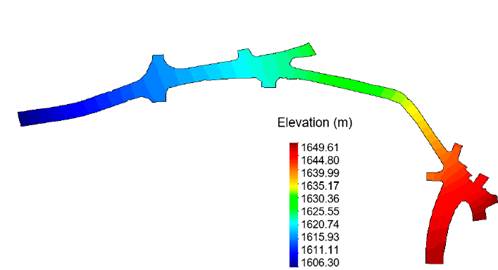
The evaluation of surface runoff is carried out on a road in the city of Medellín (Colombia) that is a two-way main street. This road sector is 330 m long and varies between 5.9 to 12.0 m wide (Fig. 2). The studied road is connected to several secondary streets that converge and diverge at different alignment sites with varying widths and connection angles (not always orthogonal). The cross section of the road is irregular which implies that the lateral slope is not always constant. This condition becomes a disadvantage when one-dimensional equations are applied for calculating the uniform flow. Fig. 2 shows the existing grate inlets. S i corresponds to the grate inlet number i and if the last letter is an S, it is simple, or a D, it is double (in blocks of multiples). Fig. 3 presents the topographic configuration of the road analyzed (elevation in meters), where the variation and irregularity of the terrain is shown, especially at the crossroads.
The hydrodynamic simulation of surface runoff has two assumptions, the first is based on the hypothesis of the uniform spatial distribution of rainfall in the contributing areas, and the second assumes that the grate inlets and sewer pipes will not work when submerged. This implies that the sewer system’s role is to free up the surface.
3.1.1. Definition of inlet flows and surface roughness
Essentially, the surface drainage system has three mass inputs: a) the rain that precipitates in the area of the analyzed road (p), b) the unit flow generated from the roofs or tributary areas, which are adjacent to the analysis section (q) and c) the flow which is not collected from upstream areas that contributes to the analysis section (Q). For the rain-runoff transformation a rational method was used with a runoff coefficient of 0.95 [13]. The friction losses are calculated with a Manning roughness coefficient of 0.015 [14].
Fig. 4 shows the contributing areas for the three types of inlet flow on the road section. The area of the adjacent homes is 1,119 ha, the area of the upstream non-collected flows is 1,758 ha, the area where rain falls directly on the road is 0.388 ha, each area is equivalent to 34.3%, 53.8% and 11.9% of the study area respectively.
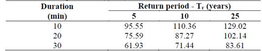
The intensity of rainfall is defined by the intensity-duration-frequency (IDF) curve of Miguel de Aguinaga station. It is operated by Empresas Publicas de Medellín E.S.P [10]. Rainfall events with durations of 10, 20 and 30 minutes were evaluated, which correspond to the spatial scale of the road section. Return periods of 5, 10 and 25 years were considered in the analysis. The first two return periods correspond to the design criteria of city manuals and the third return period included higher rainfall intensities with the objective of simulating more conservative scenarios than those proposed by local rules. The design rainfall intensities are presented in Table 1.
3.1.2. Definition of outlet flows
There are several studies that have developed formulations to represent the process of inlet flow into the grate inlet. In general, the formulations are subject to efficiency or they are orifice or weir equations [15-18]. Also, physical experimentations have been carried out with different shapes and geometries of cross bars [19,20]. Some experiments have included partially obstructed grate inlets [21-23]. These studies show a significant advance in the understanding of how inlet flow enters into the grate inlet, but they are limited to particular grates used in other countries, whose geometries differ from those used in the city of Medellín. Only the methodology presented in [16] offers a formulation based on efficiency for any geometry.
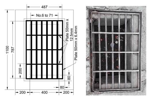
Due to the absence of hydraulic studies of the Type B gate used by Empresas Publicas de Medellín E.S.P. (Fig. 5) considered in the case study, the formulation used in [24] is proposed. It was obtained from three-dimensional hydrodynamic simulations and indirectly validated by the methodology presented in [16].
The total inlet flow is calculated by adding together the frontal flow and the lateral flow. Both are modeled using a weir equation. For frontal inlet flow (𝑄𝐹w), Eq. (3) is used in which the coefficient of frontal discharge (𝐶𝑑fw) is computed with Eq. (4):
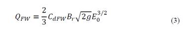

Where B r is the width of the grate inlet, E 0 and F r are the specific energy and Froude number of the upstream flow of the grate inlet respectively.
For lateral inlet flow (𝑄 Lw ) Eq. (5) is used in which the coefficient of lateral discharge (C dLw ) is computed with Eq. (6):
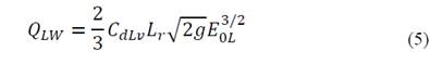
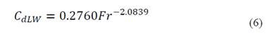
Where L r is the length of the grate inlet and E 0L is the specific energy of the lateral flow.
The remnant flow at the bottom of the road sector is obtained by a two-dimensional hydrodynamic computation which is carried out by the Iber model.
3.1.3. Sensitivity analysis
The sensitivity analysis of physical and numerical variables was carried out, considering the actual distribution of grate inlets in the study street and including all the inlet flows until the permanent regime was achieved with a rainfall intensity of 95.55 mm/h, associated with a duration of 10 minutes and a return period of 5 years.
The non-structured grid sizes of 0.75, 1.00, 2.00 and 4.00 m were simulated, and the results show small differences between the first two configurations. Therefore, it was decided that a definitive grid size of approximately 1.00 m would be used.
The Courant-Friedrichs-Levy (CFL) condition was considered with values of 0.25, 0.35 and 0.45 (the last one was calculated by default in the program). The results show several differences between the first two values, thus a limit of 0.35 was used for this condition.
The dry-wet front limit (DWF) represents the physical and numerical threshold where a cell is dry or wet. Tests were performed for wet-dry limits of 0.1, 0.5 and 1.0 mm. The results show little significant differences between them, thus a threshold of 1 mm was used.
The Iber model permits turbulence closure models and the definition of turbulent viscosity by means of different methodologies [12]: constant turbulent viscosity, the mixing and parabolic length model and the κ-ε model of Rastogi and Rodi. Differences between the results of these turbulence models and their absence in the hydraulic calculation is minimal, which indicates that the supercritical flows developed are highly influenced by the friction of the bottom and not by processes of mixing the turbulent stresses.
4. Results and discussion
Once the several numerical parameters of the hydrodynamic part of the study road are established, different scenarios are analyzed by varying the flow magnitudes, the distribution of grate inlets along the study street and carrying out the hazard analysis.
4.1. Variation of inlet flows
Three types of inlet flows were established as an initial condition, with the objective to simulate preferential flows over the road, as well as the variation of the total flow and the influence of the size and spatial distribution of grate inlets. Thus, rainfall with a return period of 5 years and duration of 10 minutes was used. Six cases were analyzed in total. The three initial cases were given the letters p, q and Q. The letters represent the direct rain on the road, the contribution of unit flow of the adjacent houses and the contribution of upstream flow, respectively. In each case, other flow contributions are considered null or assumed to go directly into the sewer system. Finally, the cases Q + p, q + p and Q + q + p are considered, which are combinations of the initial single cases.
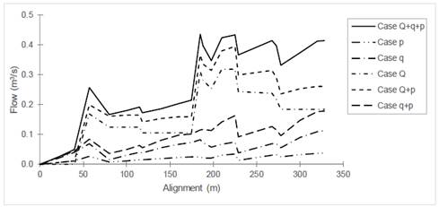
The type of contribution has a significant impact on the variation of the flow along the main road (Fig. 6). In cases where the upstream non-collected flow is considered (cases Q + q + p, Q + p and Q) a preferential flow is developed, and it is dominated by the magnitude of the input flows (point flow contributions) and represented in abrupt changes of flow along the main road. For cases where the upstream non-collected flow is not taken into account, the dominant flow develops along the study domain’s limits and along the route in an evenly-distributed way. The main characteristics of the flow are its gradualness and smoothness (cases p, q and q + p). The grate inlet location and type of inlet flow (uniform or punctual) have a significant impact on the distribution of the flow and therefore how it enters into the grate inlets.
Source: The Authors.
Figure 6 Variation of flow on the main street for different contribution inlet flows.
The specific discharge in the grid cell indicates the concentration of the flow down the preferential paths along the studied road. This variable is larger when the geometry is more irregular. This behavior shows the one-dimensional hypothesis of flow in a straight section cannot be proven.
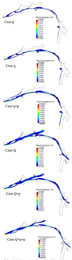
If the magnitude of the specific flow rate is filtered for the different cases studied (relative to the range of each case) and the preferential flow can be identified (Fig. 7), then the type of flow contribution has a significant impact on the specific discharge.
Source: The Authors.
Figure 7 Spatial distribution of specific discharge (filtered) for the cases with variation of inlet flows.
For cases with total inlet flow (cases with Q) the type of inlet flow becomes more relevant in the formation of the preferential flow on the road which in some cases moves from side to side. Also, the preferential flows have widths which are comparable to the road width. This is due to the magnitude of the total inlet flows. In cases where only uniform inlet flow is taken into account (cases p, q and q + p), the same preferential flows are maintained but with concentrations along the limits of the domain (beside the sidewalk) where the uniform inlet flow of adjacent houses enters. In these cases, direct precipitation contributions provide a low unit flow within in the road and thus the contribution to the formation of preferential flows is too low.
In all cases, the concentration of water in said preferential flows (higher unit flows), will indicate the possible location of grate inlets (Fig. 7). The white areas indicate locations where grate inlets are unnecessary.
4.2. Variation of rainfall intensity
Colombian National regulations define the design rainfall for a return period of 5 years for contributing areas as below 10 ha, and 10 years for areas as between 10 and 1000 ha. The rainfall intensities for durations of 10, 20 and 30 minutes and return periods of 5, 10 and 25 years are presented in Table 1.
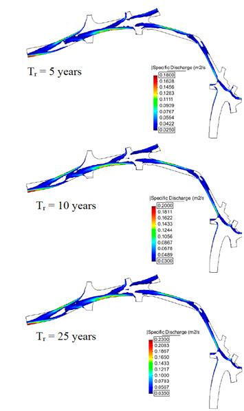
The results of the hydraulic simulation show that the increase in depth, speed and specific discharge are proportional to the increase in rainfall intensity. It is important to indicate that the preferential flow is maintained for all the intensities evaluated (Fig. 8). This can indicate that the location and distribution of grate inlets are effective for the different rainfalls analyzed.
Source: The Authors.
Figure 8 Spatial distribution of specific discharge (filtered) for a design rainfall of 10 minutes and return periods of 5, 10 and 25 years.
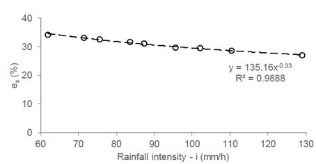
The system efficiency is the ratio between the sum of all the grate inlets’ collected inlet flow (Σ 𝑄 𝑖n ) and the total inlet flow along the road, Σ 𝑄 𝑖np (Eq. 7). The variation of the system efficiency for different rainfall intensities is shown in Fig. 9.
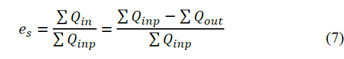
Fig. 9 shows that the system efficiency decreases when rainfall intensity increases. This behavior is due to the fact that the increase in the inlet flows along the road are distributed proportionally across the width of a cross-section of the road and thus less inlet flow respect to total inlet flow is captured by the grate inlets.
4.3. Variation of the space between grate inlets
Grate inlets spaced 50 (8 grate inlets on study road), 40 (14), 30 (19), 20 (26) and 10 m (43) apart were modeled to simulate the hydraulic behavior. Additionally, grate inlets were located on the corners of the crossroads to capture the greatest amount of flow.
The results show that decreasing the space between grate inlets generates lower water depths, especially for the 10 and 20 m configuration and where at the bottom of the analyzed road, the depths tend to become uniform and thus the total flow is stable.
The hydraulic modelling shows a decrease in flow velocity, but this is not significant unlike the other variables. The flow velocity is mainly controlled by the longitudinal slope of the terrain. The specific discharge in Fig. 10 shows that the preferential flows are kept within the road. This supports of the placement of the grate inlets and the ranges of this variable can be significantly reduced. This will increase the efficiency of the entire system by decreasing the spaces between these elements (Fig. 11).
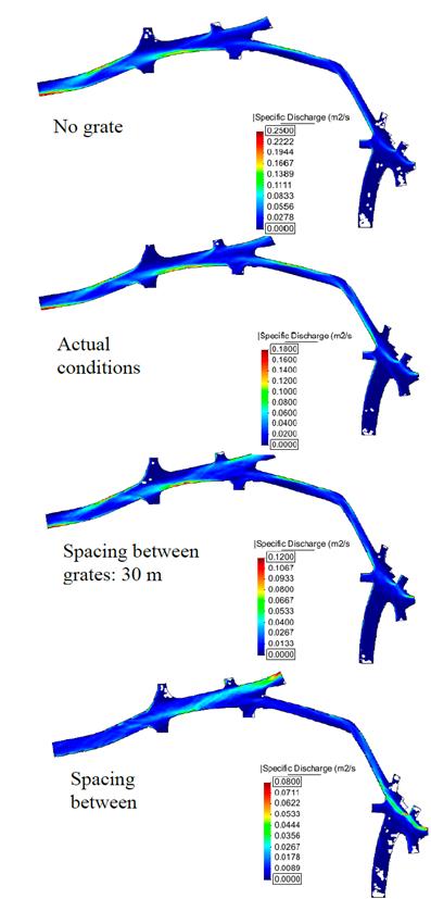
Source: The Authors.
Figure 10 Spatial distribution of specific discharge for distance between grate inlets of 10 and 30 m, actual conditions and no grate inlets.
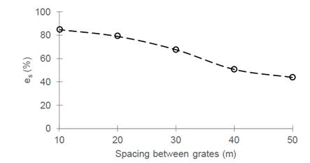
When the proposed configurations are compared with the same study section without grate inlets and existing conditions, significant reductions are found in the hydraulic variables. In particular, when the actual conditions are compared (13 grate inlets, some of them in series) to the configuration with 40 m spaces in between 14 grate inlets, the total system efficiency is increased from 30 to 50 %. This is because the proposed grate inlets are located along the preferential flow and the use of an additional simple grate inlet increases the input flow frontally. This increases the capture capacity of the system.
4.4. Analysis of hazard for pedestrians
The flow velocity and depth variables permit the establishment of risk conditions for different road users, especially pedestrians. In consequence, different limits of danger of urban floods have been established using thresholds of depth (y), velocity (v) or the product of velocity and depth (vy). These criteria are widely used for the definition of dangerous areas in river flooding, but they are not commonly used for storm flood studies in urban areas.
National regulations for the design of sewerage systems do not present official criteria for the definition of hazardous areas in urban storm floods, therefore, threshold values for urban roads proposed in [25] are used for this study. These values are as follows: 0.1 m is the maximum height of the road curb and speed is 1.88 m/s, with 0.22 m2/s as a product of vy. A two-dimensional hydrodynamic simulation defined the hazardous areas on the study road, without grate inlets, and then with grate inlets with spaces of 10, 20, 30, 40 and 50 m between them (Fig. 12).
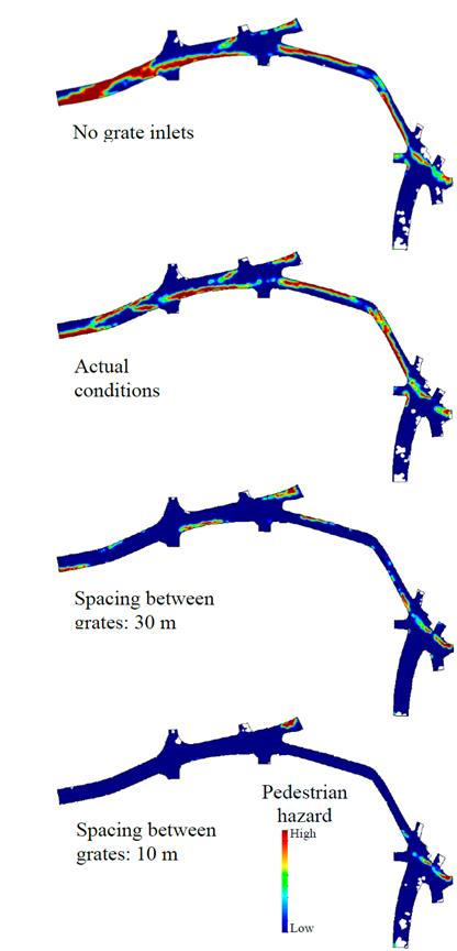
Source: The Authors.
Figure 12 Dangerous zones for pedestrians with lengths between grate inlets of 10 and 30 m. Actual conditions and no grate inlets.
In this study, the water depth threshold was not exceeded in any case because of magnitude of the flows and especially the longitudinal slope of the road which does not allow for depth to accumulate. In all cases, the speed threshold is key to the definition of unsafe areas for pedestrians, and the product of both variables to a lesser extent.
The increasing number of grate inlets and the decreasing space between them decreases the specific discharge and therefore the danger zones. Thus, dangerous conditions are minimal or negligible for the 10 m separation (Fig. 12). The result of this last configuration shows dangerous zones at the top of the domain. This is explained by the total flow that enters from the upstream areas of the study section and their reduction is due to a decrease in the total inlet flow from the upstream areas rather than an increase in the number of grate inlets. A similar analysis can be performed for the definition of hazardous areas for vehicles, using with the methodology presented in [26].
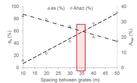
According to the simulation results, to eliminate danger for pedestrians, it would be necessary to place grate inlets at a distance of 10 m and densify them further in the areas that are still at risk (Fig. 12). This placement can become excessive in economic terms, particularly in drainage systems where these design criteria are not taken into account. Therefore, to find an approximate solution to the appropriate number of grate inlets that considers both pedestrian safety and the economic factor (number of grate inlets), the variables percentage variable of dangerous area A haz (%), and system efficiency e s (%), are plotted against distance of grate separation (Fig. 13). The dangerous area variable corresponds to the percentage ratio between the dangerous area with respect to the total area, and the total system efficiency (e s ) was defined in Section 4.3. From Fig. 13 it is possible to define a separation distance between grates of 35 m. This value balances the flow rate captured by the grate inlets and the danger zones according to the distance between them. This distance is only applicable to the road section analyzed in the present study and similar analyses must be performed for other road configurations for the practical location of grate inlets.
5. Conclusions
The results of the study and their analysis present information on the utility of two-dimensional hydrodynamic models for studying flow on urban roads, the identification of preferential flows and the estimation of inlet flow into the system, with the objective of improving system efficiency and the safety of pedestrians.
The different types of inlet flows that feed into the surface drainage system generate different runoff responses on the road. The inputs associated with uniform flows or distributed flows along the road generate gradual or smooth responses in the distribution of the inlet flow rate and road runoff. On the contrary, the upstream total inlet flows of the analyzed section generate sudden or strong changes in road runoff.
The increase in rainfall intensity for the same inlet flow conditions implies a decrease in system efficiency but allows an internal alignment of the preferential pattern of flow on the road to be preserved. This is represented by unit discharge.
The sensitivity analysis shows that the preferential flow represents the physical process of drainage on the road and that it is a good criterion to consider when studying the location of the grate inlets or identifying tools to improve the existing sewer system. This requires detailed topography and high resolution of rainfall and flow which is now possible with current instruments.
The variation of the distance between grate inlets and the estimation of hazard thresholds can be useful tools for placing grate inlets along preferential flow and to improve the system’s efficiency and road safety. The determination of the appropriate distance between grate inlets permits the hydraulic and risk limits to be accomplished. This can be an initial option for improving the integral design criteria of a sewer system.
The study of superficial urban drainage should be approached from two perspectives. The first is the reduction of the surface flow (increase of the flow rate) and the second is the reduction of the levels of danger on the road. The capture of rainwater is not the only factor. If the two factors outlined above are unknown, sewer pipes could be oversized, increasing construction, installation and maintenance costs. It is important that the two-dimensional flow analysis generate the greatest benefit from the existing infrastructure and optimization of the assets (grate inlets and pipes) of the companies that provide the sewerage service.

