


 English (pdf)
 Article in xml format
 Article references
 Send this article by e-mail
 Cited by SciELO
  Cited by Google
  Similars in
SciELO
Similars in
SciELO  Similars in Google
 Permalink
1. Introduction
Stents are vascular prostheses implanted through an angioplasty surgical procedure that helps to restore blood flow in areas with a narrowing of the lumen (stenosis) due to pathologies such as arteriosclerotic plaque. However, several studies in the literature have reported that in 30%-40% cases, lumen narrowing is observed due to plaque formation on the device about six months after the implantation [1]. One of the possible causes reported in the literature [4] is due to the geometric design and the surface finish of the prosthesis.
Cardiovascular stents to date are mainly made of nitinol, but there is a worldwide trend that these are coated. The coatings have been studied with synthetic and FDA-approved biodegradable polymers, most of which are lactic acid (PLLA),) and poly-lactic-co-glycolic acid (PLGA), which have been used even as a stent body, but PLA and the PLGA have shown that they are bioabsorbable materials but have no expandable capacity to be implanted together with the stent and that they do not suffer fractures and / or adequate mechanical support.
Recently, several medical case reports have shown that stent implants can lead to restenosis [2], myocardial infarction [3], thrombosis [4], and angina instability [5]. It is also frequently reported that stent failure can happen at any time, which can cause thrombosis, restenosis, pain, and other clinical complications in patients [6,8]. If a vascular endoprosthesis failure is diagnosed, patients will need to undergo another surgery to remove the failed stent and implant a new one to resolve the problem. To reduce the risk of complications associated with the stent, it is important to implant the most appropriate stent for the patient, for which it is necessary to have a complete understanding of the biomechanical behavior of stents with different designs, materials, and coatings. Also, stent deployment may be affected by plaque composition, such as calcified and hypocellular plaques, due to its very different mechanical behavior [9].
Most commercially available stents can generally be divided into two groups: closed cell and open cell design, with different types of connection (struts), such as peak to peak or valley to valley. In addition to the scaffold structure, modern stents tend to have drug-releasing coatings that are used to reduce and control the formation of arteriosclerotic plaque [10]. Although drug-eluting stents have mostly been used in the current clinical treatment of stenosis, very limited research has been conducted to study the mechanical behavior of drug-eluting coatings and existing work mainly focuses on drug releases. In fact, in the literature review of this study, it came across only two documents that studied coating. For example, Gu et al. [11] modeled the influence of the silicone coating during the deployment of a microstent in an artery with fusiform aneurysm. Therein, it was demonstrated that the coated stent appreciably required 30% higher pressure to expand the artery to the same extent as its bare metal version, where the coating and the strut had the same thickness (0.1 mm). Hopkins et al. [12] studied the bidimensional delamination of the stent coating during deployment, which occurred mainly in hinge regions with high plastic strain. Here, the coating started to separate depending on its thickness, material, and curvature of the hinge.
The purpose of this research is to analyze the mechanical behavior of a PVOH-based stent coating with and without the presence of carbon nanotubes and to assess the effects of this membrane interacting with local hemodynamics through a fluid-structure computational study (FSI).
2. Material and methods
2.1. Geometry
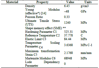
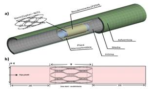
The study scope includes a stent and a coating located in a section of the arterial vessel (Fig. 1a). Since its technical information was available, the stent used was the nickel-titanium (nitinol) Cypher® stent by Xience. The length, internal diameter, and thickness of the stent were 8 mm, 3 mm, and 150 μm, respectively. The CAD model was created using the CAD Solidworks® software. The coating is a thin 10 μm layer attached to the surface of the stent. The blood vessel with a length of 20 mm and a wall thickness of 1 mm was simplified to a cylinder with an axi-symmetric stenotic plaque with a length and maximum thickness of 6 mm and 0.4 mm, respectively.
Source: The Authors.
Figure 1a Geometry of the control system. Coated stent, plaque, and stenotic artery. Figure 1b. Description of the fluid volume, input length, (development), interaction length (stent coating zone), and output length (inertia).
The internal diameter in the healthy section and in the stenotic plaque is 4 mm and 3.35 mm, respectively. For the wall, the three tissue layers were included, i.e., intima, media, and adventitia, with a thickness of 0.27 mm, 0.35 mm, and 0.38 mm, respectively [13].
2.2. Materials
The Cypher® test stent is made of nickel-titanium (nitinol); the mechanical properties of which is shown in Table 1 [14,15,16,17].
2.3. Governing equations and border conditions
2.3.1 Fluid
The fluid was assumed as incompressible, with a density ρ = 1060 kg/m3 and a dynamic viscosity of 0.0035 Pa s, under the domain of the mass and momentum conservation equations [20].
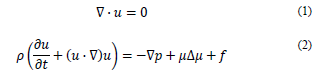
where u is the flow rate, p is the static pressure and t is time.
The fluid model is assumed as homogeneous and incompressible and it was based on the power law considering blood as non-Newtonian [21]. In this model, the shear stress 𝜏(𝑁/𝑚2) is calculated as:
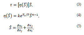
where k = consistency index (𝑘g𝑠𝑛−2/𝑚), n = power law index, T0 = reference temperature (K), µ0 = minimum viscosity limit (kg/m s), and µ∞ = limit of maximum viscosity (kg/m s).
The assumed values are [21] µ0 = 0.0001 Pa s, µ∞ = 0.1 Pa s, n = 0.7, T0 = 310 K y k = 0.01691 (𝑘g𝑠𝑛−2/𝑚)
For the input speed and the output pressure, a pulsatile flow was considered, which was programmed in two functions (UDF) [22] as follows:
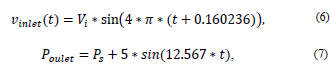
where Vi = Initial speed, Ps = Output pressure, t = time
2.3.2 Structural
The governing equation for the solid domain is the momentum conservation equation.
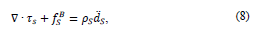
where ρs is the density of the coating wall, t
s
is the stress tensor of the solid, 𝑓𝑆
𝐵 is the forces of the body per volume unit, and
 is the local acceleration of the solid.
The stent coating is polyvinyl alcohol (PVOH) reinforced with carbon nanotubes at 0.1%, 0.2%, and 0.3% by CNT weight. The material was modeled with a hyperelastic behavior according to the Yeoh model. Therefore, this model has been chosen to describe the hyperelastic properties of the polymer [18,19]:
The Yeoh model is applicable for a much wider range of strain.
This model is able to predict the stress-strain behavior in different strain modes from data obtained in a simple strain mode such as the uniaxial extension
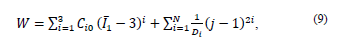
where W = strain energy potential,
 first invariant of the Cauchy-Green strain tensor
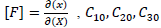
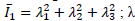 : main elongations, J = Jacobian determinant of the elastic deformation gradient F defined as
 material constants and d
1,d
2,d
3 = incompressibility parameters.
material constants and d
1,d
2,d
3 = incompressibility parameters.
The constant values are shown in Table 2. The constants of the material were calculated in Ansys® after entering the experimental data of the tests conducted in this work (see Section 4).
Table 2 Material constants of PVOH without reinforcement and PVOH reinforced with CNT for the Yeoh hyperelastic model.
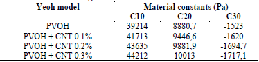
Source: The Authors.
The FDA has some evaluation criteria that regulate the structural analysis of a vascular prosthesis. Some parameters considered in this study are as follows.
2.3.2.1. Longitudinal contraction
This criterion is used to calculate the shortening of the prosthesis at the axial level during a cycle and is expressed by equation 11:
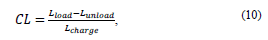
where CL (longitudinal contraction), L looad (coating length with working pressure), and L unlooad (coating length without working pressure).
2.3.2.2. Radial contraction
This criterion is used to calculate prosthesis reduction at the radial level. This criterion depends on the type of material and its behavior, due to its elastic recoveries, as well as on the loads to which the prosthesis is subjected. Its calculation is expressed by the following equation:
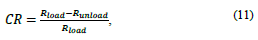
where CR (radial contraction), R load (radius of the coating with the working pressure) y R unload (radius of the coating without the working pressure).
2.4. Mesh
2.4.1. Solid domain
The mesh of the coating’s solid domain was meshed with a shell-like element known as SHELL 181, which is suitable for analyzing structures with thin-to-moderately-thick layers. It is a four-node element with six degrees of freedom in each node: with movement in the x, y, and z directions and rotations around the x, y, and z axes. It adapts very well for nonlinear high strain applications and for modeling of composed materials [23]. The final mesh comprised approximately 70000 elements. The stent was meshed with SHELL 281 type elements, with similar characteristics as SHELL 181. Similar to SHELL 181, SHELL 281 is suitable for nonlinear high strain applications, but the SHELL 281 element has eight nodes with six degrees of freedom in each node: with movement and rotations in the x, y, and z axes [23]. Approximately 50000 elements were used; the vessel wall and the plaque were entangled with MAPPED elements, which is the default element used by the software to mesh thick-layered geometries. A total of 20,000 elements were used to generate this mesh. The balloon was meshed using hexahedral SHELL 181 elements, with an approximate number of 4500 elements [23].
2.4.2. Fluid Domain
The fluid domain was meshed with approximately 900000 tetrahedral PRISMA elements of four nodes, adequate for the preparation of complex geometries. In fact, using these triangular or tetrahedral elements to generate unstructured meshes saves times since this mesh allows the grouping of elements in selected regions of the flow domain. The quality of the mesh was evaluated based on the aspect ratio for the structural domain and the Skewness for the dynamic fluid domain. The values obtained were of 1.1 and 0.25, respectively, which indicate a very good behavior in the generation of the elements in order not to cause convergence errors or changes that interfere with the results [23,24]. The mesh was refined taking into account that they were compliant (the elements must be equal in size to obtain better transfer of information from one element to another) between the different subdomains of both the solid (stent coating) and the fluid (blood-coating) domain, with the sole purpose of reducing simulation resolution times [23].
2.5. Loads and Restrictions
Initially, a linear load that emulates the inflation and deflation processes of the balloon on the coated stent was applied to the model. The applied displacement was 35 microns, equivalent to a pressure of 0.9 MPa [25]. The inflation and deflation times were 0.5 s and coated stent ends were fixed emulating their fixation on the catheter. The contact between the stent and the coating was modeled as a frictionless surface, with contact adjustment and a stiffness factor of 0.01 that the software includes by default [26].
Additionally, a pulsatile profile is considered for the fluid with a sinusoidal pattern, with a maximum velocity at the inlet of 50 cm/s during the systolic phase and a minimum velocity of 10 cm/s during the diastolic phase. For the output, also a pulsatile pressure with a maximum of 120 mmHg and 80 mmHg was applied as a minimum point. Therefore, considering the mean pressure of the two phases, around 100 mmHg is used as the static manometric pressure at the outlet point [22]. If the heart rate is 120 beats per minute, the duration of each period is 0.5 s.
3. Results
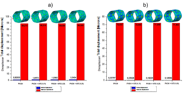
Figs. 2, 3, and 4 denote the behavior of the PVOH coating with and without carbon nanotubes (displacement, stress, and strain) during the unfolding process within an artery with plaque obstruction. The results obtained show that as the CNT percentage increases, a small percentage variation is registered in its mechanical properties.
Source: The Authors
Figure 2 Total displacement of the PVOH coating [Microns] with and without nanoreinforcement: a) Displacements when the pressure balloon is maximum P = 0.9 MPa; b) Displacements when the pressure balloon is minimum P = 0 MPa.
Source: The Authors.
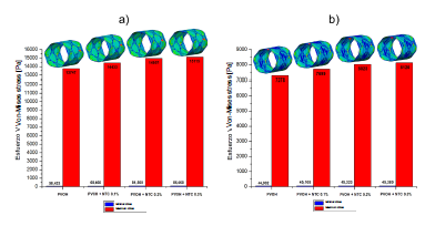
Figure 3 Normal von Mises stress of the PVOH coating [Pa] with and without nanoreinforcement: a) Stress when the pressure balloon is maximum P = 0.9 MPa; b) Stress when the pressure balloon is minimal P = 0 MPa.
Source: The Authors.
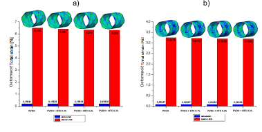
Figure 4 Strain of the PVOH coating [Pa] with and without nanoreinforcement: a) Strain when the pressure balloon is maximum P = 0.9 MPa; b ) Strain when the pressure balloon is minimal P = 0 MPa.
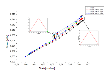
Fig. 5 displays the stress-strain diagram of the coatings with and without nanoreinforcement.
Source: The Authors.
Figure 5 Stress-deformation curve of the coating: a) PVOH without reinforcement; b) PVOH reinforced with 0.1% of CNT, c) PVOH reinforced with 0.2% of CNT and d) PVOH reinforced with 0.3% of CNT.
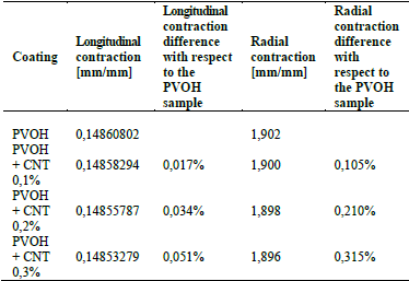
Table 4 shows the results of longitudinal and radial contraction and the percentage difference that exists between the PVOH coating with and without CNT.
Table 4 Results of the longitudinal contraction and radial contraction of the coating: a) PVOH without reinforcement; b) PVOH reinforced with 0.1% of CNT, c) PVOH reinforced with 0.2% of CNT, and d) PVOH reinforced with 0.3% of CNT.
Source: The Authors.
3.1. Fluid-structure analysis
In the case of fluid-structure interaction, there is a pulsatile flow and a covering structure with hyperelastic characteristics, which present a speed and shear stress solution for each instant of time.
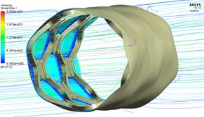
3.1.1. Development of speed in the coating area
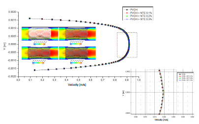
As seen in Fig. 6, the speed does not vary significantly, because the difference that exists in the radial contraction of the nanoreinforced coatings with respect to the coating of only PVOH is very small (Table 4).
Source: The Authors.
Figure 6 Differences in velocity profiles of the zone-coating at time instant t = 0.1 s.
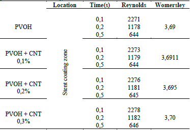
In Table 5, it is observed that the Reynolds number generated throughout the stent coating system for the four cases narrowly surpasses the critical Reynolds Re = 2200 [27].
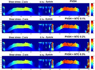
3.1.2. Mapping of the shear stress profiles on the surface of the coating with and without nanoreinforcement
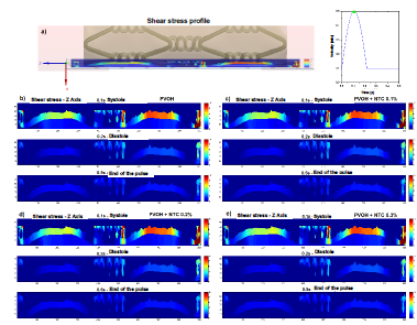
Fig. 7 shows the profiles of the shear stresses that are generated in an exposed section of the coating in different time instants. In Fig. 8, a comparison is made in the mapping of the shear stresses generated in the surfaces of the coatings with and without CNT, as it can be observed is practically imperceptible the change in the results of these efforts, because the speeds also recorded a very small change as a result of the few difference that there was in the radial contraction of each material.
Source: The Authors.
Figure 7 Mapping the shear stress on a section of the surface of the coating. a) section of the stent coating system chosen to perform the mapping of the shear forces. b) profile of the shear stress in the Z axis - t = 0.1 s (systole), 0.2 s (diastole), and 0.5 s (end of the pulse), PVOH c) profile of the shear stress in the Z axis - t = 0.1 s ( systole), 0.2 s (diastole), and 0.5 s (end of pulse), PVOH + CNT 0.1%. d) profile of the shear stress in the Z axis - t = 0.1 s (systole), 0.2 s (diastole), and 0.5 s (end of the pulse), PVOH + CNT 0.2%. e) profile of the shear stress in the Z axis - t = 0.1 s (systole), 0.2 s (diastole), and 0.5 s (end of the pulse), PVOH + CNT 0.3%.
4. Discussion
As shown in the results presented in Figs. 2, 3, and 4, corresponding to the case of implanting the coated stent, it is observed that as the CNT percentage increases, a percentage variation of 0.05%, 0.08%, and 0.1% is registered in the total displacements, 4.7%, 8.1%, and 9.05% in the von Mises stress, and a decrease in percentage variation of 1.55%, 2.67%, and 2.98% in total strain. All these variations occurred in coatings reinforced with carbon nanotubes (0.1%, 0.2%, and 0.3% (wt)) with respect to the coating without CNT and at the maximum pressure point.
As seen in Fig. 5, the system begins a stage of recoil or deflection. During deflation, there is a recovery in elastic deformation and radial pressure. As a result, the stent coating system has a stronger tendency to recover its hyperelastic deformation. This forced the stent coating system to retreat in the four simulation cases 0.01724 mm or 19.31% (PVOH), 0.017308 mm or 19.38% (PVOH + 0.1% CNT), 0.017361 mm or 19.43% (PVOH + 0.2% CNT), and 0.017377 mm or 19.45% (PVOH + 0.3% CNT). All values are taken from the point of maximum pressure until pressure reaches zero.
Table 4 denotes that there is an imperceptible difference in the longitudinal contraction as in the radial contraction, causing only a small variation in the speed and shear stress results, as shown in Figs. 6 and 7.
For the fluid-structure case, Fig. 6 denotes that the velocity does not vary significantly because the difference in the radial contraction of the nanoreinforced coatings with respect to only PVOH coating is very small in the range of 0.105%-0.315%.
As observed in Table 5, the critical laminar regime only just exceeded, which means that the regime is slightly turbulent since the flow comes into contact with the stent structure, causing small turbulences in the system wall. As time progresses, speed as well as the Reynolds number decrease, causing a laminar regime throughout most of the pulse. The Womersley number determines the shape of the velocity profile. As α in the zone of reduction presents a value less than 3, the profiles are completely parabolic that indicates that the flow is fully developed.
As can be observed in Figs. 7 and 8, the difference is almost imperceptible in the mapping of the shear stress profiles since the percentage in the radial contraction of the coatings with nanoreinforcements is not greater than 0.3%. Therefore, the PVOH velocity 0.93671 [m/s] - PVOH + CNT 0.3% 0.93966 [m/s] (Fig. 6) and the shear stresses PVOH 24,7405 [Pa] - PVOH + CNT 0.3% 24,8184 [Pa] increases.
Stagnation and re-circulation points were considered in the simulation, which can start thrombus formation Fig. 9.
5. Conclusions
In this study, the effects of the selection of the coating material and its expansion behavior on a stent have been studied based on an FSI simulation with local hemodynamics and the membrane implanted inside a stenotic artery. The results of this study showed that at a given deployment pressure and as the CNT percentage increases, a percentage variation of no more than 0.1% in total displacements, 9% in the von Mises stress, and a decrease in the variation in the percentage of total deformation of less than 3% is reported. All these variations occurred in coatings reinforced with carbon nanotubes (0.1%, 0.2%, and 0.3% (wt)) with respect to the coating without CNT.
Therefore, the addition of carbon nanotubes as reinforcement is not significant since the mechanical properties of the material are not considerably modified. It is worth mentioning that the carbon nanotubes used to create the coating applied in the macroproject from which this study is derived had the purpose of transporting anti-adherent molecules of oxidized low density lipoproteins, which are the cause of the formation of the atherosclerotic plaque.
As it can be observed, the reduction speed developed at the selected instant of time (maximum speed point: systole), causing a slightly turbulent regime, due to the fact that the blood flow collides with the structure of the stent. Recirculation zones in which there would be an accumulation of blood fluid, which would lead to a possible thrombus, were not present. In the same way, as the flow moves away from the stent coating system and pulse time progresses, the fluid recovers the laminar regime and its initial velocity magnitude.
Another aspect to take into account is the percentage variation in the results of the recoil effect, the longitudinal and radial contraction that occurred at implantation time are very low in cases where they only exceed 0.3%, causing an insignificant speed variation in the reduction zone and therefore, an imperceptible variation in the shear stress zones where the coating is exposed.

