


 English (pdf)
 Article in xml format
 Article references
 Send this article by e-mail
 Cited by SciELO
  Cited by Google
  Similars in
SciELO
Similars in
SciELO  Similars in Google
 Permalink
1. Introduction
There is a wide literature reporting the usefulness and effectiveness of synthetic aperture radar (SAR) in diverse fields, including climate monitoring, seas, terrestrial ice layers, mining, topographic surveys, land classification, hydrocarbon pollution monitoring, global positioning systems, among others [1]. The principle of operation of SAR systems can be summarized as the construction of images by phase discrimination between the microwave pulse signals transmitted and received by the radar when they are incident and reflected by the surface of an object under study [2-5].
Among the various technological aspects that should be addressed in designing and implementing SARs, the design of transmitting and receiving antennas is an important one. In general it is required that these antennas are small, lightweight, low cost, have good performance and be easy to manufacture. This makes microstrip antennas excellent candidates for SARs.
One of the main goals of the antenna design is to obtain a radiation pattern that exhibits a horizontal beamwidth that leads to an azimuthal spatial resolution appropriate for the purposes of the radar [1-7]. Other important figures of merit for the antenna are return loss, polarization purity, power, and gain.
In this article, we describe the designing of two identical 1 × 4 patch antenna arrays to be incorporated in a linear frequency modulated (LFM) continuous wave (CW) synthetic aperture radar prototype implemented at the Ecuadorian Space Institute (IEE). We aim with this work to achieve a very important expertise in the area of antenna engineering for synthetic aperture radars within the Instituto Espacial Ecuatoriano, that permit us to trace a roadmap for designing and implementing, in a medium to long-term, an operative radar for remote sensing purposes. The main goal of the project is to obtain a horizontal beamwidth of ΔθH ≈ 24° in order to achieve an azimuthal resolution better than 20 cm.
At first, the antennas were designed using its transmission lines theoretical model [7-9]. Later on, the resulting geometry was optimized using the High Frequency Electromagnetic Field Simulation (HFSS) of Ansys [10] and the Advanced Design System (ADS) from Agilent [11].
We used an inset to feed the patches, and T-Junctions and λ/4 adapters to feed the array [9,12].
Once the antennas were fabricated, we measured the return loss (RL), the standing wave ratio (SWR), the resonance frequency (f 0 ), the bandwidth (BW), the gain, and the radiation pattern.
Finally, we incorporated the antennas into the radar and made measurements on a test polygon. We estimated the cross-range spatial resolution and found good agreement with the theoretically expected value.
The rest of this article is structured as follows: in Section 2 we describe the antennas design procedure and we present some simulation results. In Section 3 we describe the experimental characterization results of the constructed antennas. In Section 4, we briefly analyze the antenna’s performance, once incorporated to the radar, and finally in Section 5 we give some conclusions.
2. Antenna design and optimization
2.1. Substrate selection and base antenna design
The geometry of the array base antenna is shown in Fig. 1. The base antenna consists of a thin rectangular film of conductive metal of thickness t, width W and length L, on a dielectric substrate of thickness h and dielectric constant εr, resting on a broad conductive metal film that serves as a ground plane.
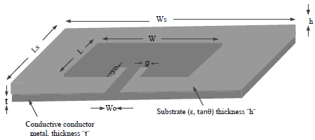
Many substrates are commercially available for designing a microstrip antenna. The dielectric constant of these substrates can vary from a minimum of 2.2 to a maximum of 12: 2.2 <εr <12. According to [8], a dielectric constant close to the lower limit of 2.2 and a high thickness provide the best bandwidth and the best performance, even though at the expense of a larger size. So, to favor the efficiency of the antenna we have chosen a dielectric constant of εr = 3.5 as initial guess. To settle the thickness h of the substrate the bandwidth of the radar was taken into account. The central operating frequency of the radar is f 0 = 2.44 GHz and the expected bandwidth is of about 24 MHz (1% of f 0 ). From the information contained in Fig. 2 of [13], best reproduced as Fig. (14.27) on page 854 of [8], we have determined that a minimum substrate thickness h of approximately 0. 012 𝜆 0 , or h = 1.48 mm, is required to achieve such a bandwidth for a dielectric constant of 3.5. These guess values (εr = 3.5 and h = 1.48 mm) served for searching a commercially available substrate. After consulting the Rogers database [14] we have selected the RO4003C substrate (εr = 3.55, h = 1.524 mm) for the project.
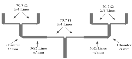
Given the selected substrate, we have designed the base patch antenna theoretically using the equations derived from the Transmission Line Theory as described in Reference [8], pages 817-820: equations (14.1), (14.2), (14.5), (14.6) and (14.7). The design equations given in [8] were transcribed directly in a GNU Octave script for a resonance frequency f 0 = 2.44 GHz. By the other hand, we calculated the minimum dimensions of the substrate, W s and L s , according to [15] as:
By the way, we have calculated the insertion point y 0 of the feeding strip in the patch, its width W 0 and its separation g from the antenna using the equations available in [8,16].
2.2. 1 × 4 patch-antennas array design
We designed a broadside horizontal array of 4 elements using the equation for the theoretical array factor given in [8] using GNU Octave. We carried out some iterations for the separation d between two successive base antennas until a theoretical horizontal beamwidth of ΔθH ≈ 24° was obtained.
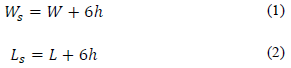
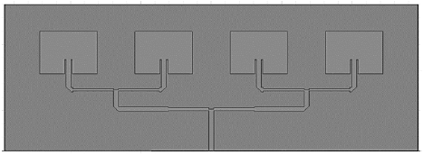
We used three T-junctions to feed the array as shown in Fig. 2. Each T-junction is made of a 50 Ω line connected to two 70.7 Ω lines. The 70.7 Ω lines have been cut to a length of 1.92 mm (λ / 4) to properly transform 50 Ω to 100 Ω. A chamfer of 3.8266 mm was made in the outer corner of right angles in all the 50 Ω lines. We calculated the chamfer length as √2 x, where x = D × M / 100, D is the length of the diagonal of the corner and M is determined, for wl/h≥0.25 and εr <25, as [9,13]:
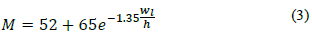
Where W l = 3.84 mm is the width of the 50 Ω line [15]. We reduced the width of the horizontal branches of all T-junctions vertically in the joining point by an amount of 1.34 mm (~ 0.6 𝑤 𝑙 ) in accordance to [13,15].
With these preliminary theoretical geometric values, we proceeded to optimize the 1x4 patch antenna array by successive simulations in HFSS until the results shown in Fig. 3 and Table 1 were obtained.
Source: The Authors.
Figure 3 Linear arrangement of 1 × 4 patch antennas obtained after optimization with HFSS.
Table 1 Geometric and performance parameters of the 1×4 patch antenna array obtained via simulation using HFSS.
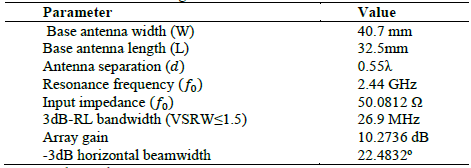
Source: The Authors.
As can be seen on Table 1 the simulated array exhibits an input impedance very close to 50 Ω at resonance and a horizontal beamwidth of 22.4832°.
3. Antenna array experimental characterization
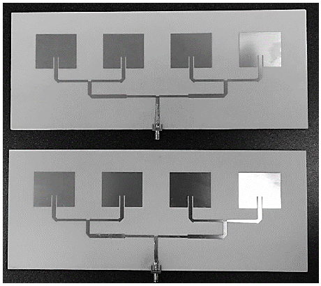
With the optimized geometric parameters given in Table 1 we constructed the two patch antenna arrays that are shown in Fig. 4.
Source: The Authors.
Figure 4 Antenna arrays constructed using the geometric parameters given in Table 1.
Then, we characterized experimentally the constructed antennas in an anechoic chamber. We measured the following parameters of interest: a) the return loss RL in the 2.4 to 2.5 GHz band, b) the standing wave ratio SWR in the 2.4 to 2.48 GHz band, c) the resonance frequency f 0 , d) the bandwidth BW, e) the gain, and f) the radiation pattern.Fig. 5 shows the antenna return loss measured experimentally together with the RLs obtained via simulation using HFSS and ADS.
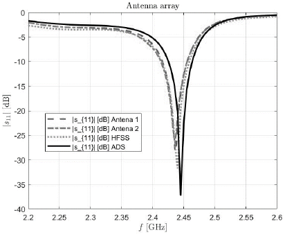
We can read from Fig. 5 a resonance frequency of f 0 = 2.436 GHz corresponding to the minimum value of | S11 |.
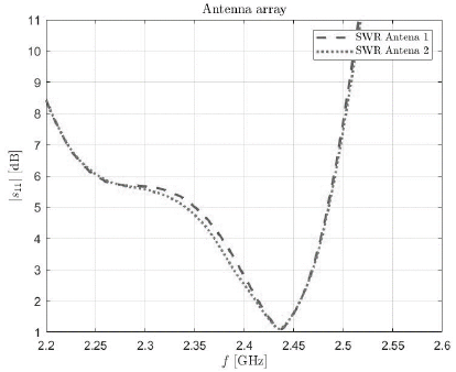
Fig. 6 shows the measured SWR of both antennas. The antenna bandwidth can be determined from any of Figs. 5 and 6. From Fig. 6 we have estimated a 1.5-SWR bandwidth of BW = 24.0121 MHz.
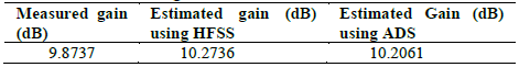
For estimating the patch antenna array gain (at f 0 = 2.436 GHz), we settled the distance between the antennas to r = 2.05 m, and with the vector network analyzer, we measured a |S21|of -26.633 dB. Subsequently, we determined the gain using Equation 17.15 of reference [8]. Table 2 shows the measured gain value of the antennas together with the values estimated using HFSS and ADS.
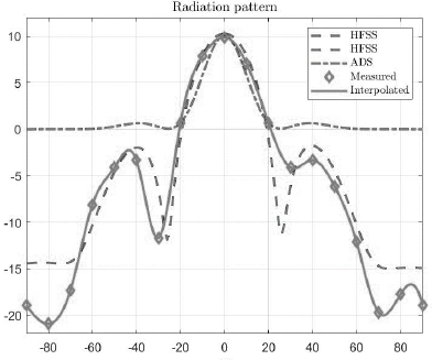
In the anechoic chamber, we also measured the antenna array radiation pattern and then we plotted the measured pattern together with those estimated by HFSS and ADS. Fig. 7 shows the results obtained.
4. Antenna performance on the radar
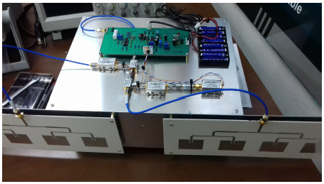
Finally, we incorporated the two implemented antennas described in the previous section to the LFM-CW radar prototype as shown in Fig. 8.
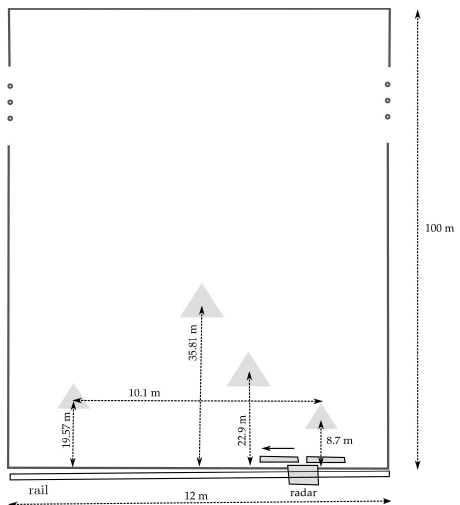
For testing the synthetic aperture radar prototype, we arranged a rectangular polygon of 12m x 100m with four corner reflectors in it as shown in Fig. 9. On one of the shorter side of this polygon, we installed the radar on a rail at a height of 1.2 m above ground, and we slid it following a stop and go scheme whilst taking samples of the echo received every 10 cm.
Next we post-processed the raw data collected by the radar in GNU Octave using the ω-κ algorithm, and we generated an image of the scene inside the polygon as shown in Fig. 10.
Source: The Authors.
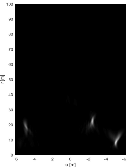
Figure 10 Image generated from raw data collected by the radar using the ω-κ algorithm.
In the image of Fig. 10, we observe three luminous targets corresponding to the three closest corner reflectors in the scene. The farthest target does not appear in the image due to its poor azimuthal phase registration and its 30 dB bigger free space loss.
Afterwards we processed the image on Fig 10 with GNU Octave; we measured graphically the azimuthal width of the sync-like point spread function of each target [4,5]. As the first zero crossing of the sync-like function determines the azimuthal resolution of the radar, we assessed an azimuthal resolution of approximately 0.15m.
By the other hand, as it is well known, the theoretical azimuthal resolution is given by the expression [4]:
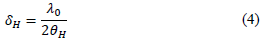
where λ0 is the free-space wavelength at f 0 , and ΔθH is the antenna horizontal beamwidth. By substituting the values of λ0 = 0.12m, and ΔθH = 0.42 rads in Eq. (16), we would expect a theoretical azimuthal resolution of δH = 0.14m.
5. Acknowledgements
We thank Luis Ledezma, from the Jet Propulsion Laboratory, California Institute of Technology, for comments and suggestions that helped improve this manuscript.
This work was funded by the Prometeo Project of the Secretariat for Higher Education, Science, Technology and Innovation of the Republic of Ecuador.
6. Conclusions
We have built two 1x4 patch antenna arrays for a LFM-CW synthetic aperture radar prototype developed at the Ecuadorian Space Institute (IEE: Instituto Espacial Ecuatoriano).
We installed the arrays in the radar, and we tested the radar in a probing polygon with four corner reflectors, sliding the radar on a rail and using a stop and go scheme. Subsequently, we focused the raw data collected by the radar using the ω-κ algorithm using GNU Octave. As a result, we generated a radar image of the scene inside the polygon. On the image itself, where only the three most luminous targets were correctly focused, we estimated graphically the horizontal resolution of the radar obtaining a value coinciding with the expected theoretical one.

