


 Inglés (pdf)
 Articulo en XML
 Referencias del artículo
 Enviar articulo por email
 Citado por SciELO
  Citado por Google
  Similares en
SciELO
Similares en
SciELO  Similares en Google
 Permalink
1. Introduction
Entropy generation minimization in a system (EGM), has been used as an optimization strategy, and has been endorsed and implemented in various fields of engineering over the last decades. Adrian Bejan, precursor and diffuser of the method, affirms the foundation for EGM is the theorem of Gouy-Stodola [1]. According to this theorem, the work lost or not available in a system is defined by eq. (1), in which To is the reference temperature of the system, and Ṡ gen the variation of its entropy generated with time.

In this way, minimizing Ṡ gen involves minimizing lost or unavailable work. In other words, minimizing Ṡ gen makes the system less irreversible, and therefore, thermodynamically optimal. A detailed description of what entropy is and what entropy is not and the generation of entropy, can be read in [2]. On the other hand, EGM as a design method is clearly detailed in [3], and in [4]. An application of EGM to systems that simultaneously combine mass and heat transfer is exemplified in [5].
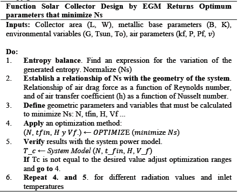
The need to take full advantage of renewable solar energy has made the use of EGM in the design of solar collectors recurrent (see Fig. 1). From the application of the second law of thermodynamics, [6] estimated as promising areas for fossil fuels to be displaced by solar energy, those whose entropy was comparable with the entropy of the systems that convert solar energy into hot. Kreider notes that, in effect, fossil fuels are sources of low entropy, generally employed in high entropy applications. Subsequently, Bejan performs a detailed analysis of the EGM in isothermal and non-isothermal solar collectors [7], in which a dimensionless expression is defined for the variation of the entropy generated, based on entry and exit temperatures, and the maximum temperature of the collector. This showed that minimizing the entropy generated in a solar collector is equivalent to maximizing its exergy flow. Therefore, [8], considering this fact, optimized the model of different types of solar heaters, by maximizing their exergy balance [9].
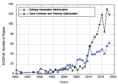
Source: The Authors.
Figure 1 SCOPUS publications referents to EGM and to Solar Collector and Thermal Optimization.
Otherwise, [10], apply the EGM to optimize the design of a grain solar dryer, with natural air circulation. An analysis similar to that developed by Bejan is also presented in [11] by Saha, and in [12] by Torres. In other works of Torres, there are two additional developments: one explores the application of the EMG in solar collectors for drying processes [13], and another explores the application of the EMG to determine the temperature and length of the optimal fluid conduit channel, in solar collectors of different configurations [14]. More recently, several works have studied the efficiency and optimization of flat-plate solar collectors, too. Some examples include [15] and [16]. Others include [17] and [18], where the authors focused on analyzing the effect of airflow orientation. They also studied how the geometry of plate fins influences the process. They found that using a counter flow and a corrugated absorber makes the process more efficient. Other works have also shown that it is better to use a flat plate with fins rather than a smooth one, and that the number of fins strongly influences exergy maximization [19,20,21].
This work explores the influence of plate geometry in thermal optimization, considering two variation sources for the entropy generation rate: heat transfer and airflow velocity. Considering that despite the number of published works, the effect of airflow velocity is yet to be addressed, including the latter is paramount, as this variable directly influences air temperature regulation at the output of the collector, depending on different values of solar irradiance. This is the main research objective and the principal contribution of this paper.
We treated the flat plate in the collector as a finned heat sink. We varied airflow velocity, and also, we analyzed dimensionless entropy variation for an increasing number of fins, as well as for different fin thicknesses and heights. This work synthesizes the design method for a solar collector that minimizes entropy generation rate. Such results are important for future applications, e.g. related to solar grain drying. In this article the entropy generation model is presented along with the equations that define the design of a fin with a constant cross section. Then, in the results section, the optimization problem is developed by means of PSO (Particle Swarm Optimization). Finally, some of the most relevant conclusions are presented.
2. Methods and modeling
The logical sequence followed in the present work, entailed:
Calculation of the variation of the entropy generated in a flat plate solar collector.
Determination of the drag force of the airflow in the collector, from the calculation of the Reynolds number.
Determination of the heat transfer coefficient for the airflow in the collector, from the calculation of the Nusselt number.
Metaheuristic optimization of the variation of the entropy generated, and determination of the values corresponding to the quantity, thickness and height of the fins in the collector, as well as the velocity of the surrounding flow, which minimize the variation of the entropy generated.
Simulation of the variation of the entropy and the efficiency in the collector, with respect to the variation of the number, thickness and height of the fins, and the velocity of the flow.
The mathematical expression for the dimensionless variation of the entropy generated in the collector is broken down below.
2.1. Entropy models generated in a non-isothermal flat plate solar collector
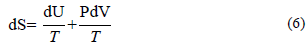
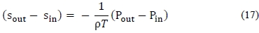
The entropy balance in a system is defined in [22] as,

From the above equation, we can express the velocity of the variation of the entropy generated in the collector as,
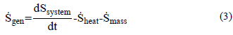
This entropy generated velocity of variation is therefore composed of three parts: the variation of entropy in the system, the variation of entropy by heat transfer, and the variation of entropy by mass flow (which, for the case of the collector, is air). Each component is described below.
2.1.1. Variation of entropy in the system
The variation of entropy in the system is caused by the non-isothermal condition of the metal plate in the collector. According to the first law of thermodynamics, the internal energy of a system in which heat generates work is defined by,
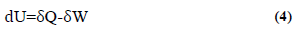
The variation of entropy in the system is given by,
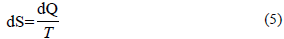
Therefore, from the two previous equations, and keeping in mind that the work generated is equal to the product pressure by volume (PdV), we have to,
In the collector, the variation of the internal energy dU, is proportional to the variation of the temperature in its plate, according to the following equation:
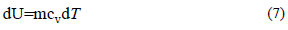
with m equal to the mass of air that circulates through the collector, and cv to its specific heat. On the collector, there is no variation in volume, so that dS can be defined as,
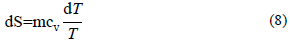
When integrating, you get that,
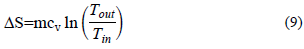
Therefore, the velocity of variation of the entropy in the system is,
2.1.2. Variation of entropy by heat transfer
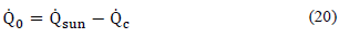
The variation of the entropy by heat transfer is given by the solar radiation, and by the heating of the air that enters the collector from the outside (caused precisely by said radiation). This can be expressed as,

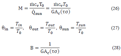
being, Qsun and Q0, the heat of the sun and of the air, respectively. From the above equation, we get that,
with T0 equal to the ambient temperature. Qsun is proportional to the product of the average solar radiation (G, Wm-2), by the area of the collector,

with, τσ equal to the absorbance product of the transmittance in the collector.
2.1.3. Variation of entropy by mass flow
The variation of entropy by mass flow is due to the flow of air that circulates through the collector. This variation is defined as,

The variation of the enthalpy in this airflow is given by,
Therefore,
and considering the enthalpy variation close to zero, it is determined that,
Consecuently,
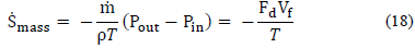
where, T, Fd and Vf are the temperature, force and the average velocity of the air, respectively.
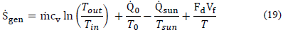
2.1.4. Entropy generation
Based on the above definitions, the rate of entropy variation in the isothermal collector is defined by,
From a general energy balance,
 is
is
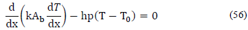
 can be expressed as a function of the temperature delta in the plate, starting from the differential equation that defines the energy balance in the collector,
hence it will have that,

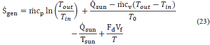
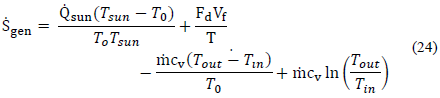
Ṡ gen can then be written as,
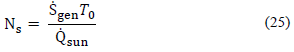
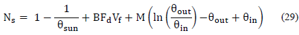
If the definition proposed by Bejan is used for dimensionless entropy variation, Ns,
and if it is used,
results that,
M is found from the differential equation of the energy balance in the collector. Solving this differential equation, we obtain that,
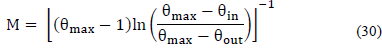
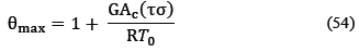
where θmax is the maximum temperature that the collector can reach, which is determined by solving the energy balance in the collector, too. This is defined in a dimensionless way, like,
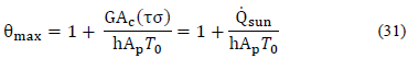
In the definition of θmax, h is equal to the heat transfer coefficient of the air in the collector, and Ap equal to the heat transfer area in the collector (area of the metal plate), which is at least twice the area of the collector, if a plate without fins is considered. In effect, Ap will increase with the number of fins on the plate.
2.2. Geometry of the Plate of the Collector
The geometry of the collector plate is associated with the expression to find Ns, in the calculation of the drag force (which depends on the Reynolds number), of the air velocity, and in the calculation of h (which depends on the number of Nusselt). The procedure is similar to the developments made for finned heat sinks, such as those presented by [23]-[27].
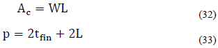
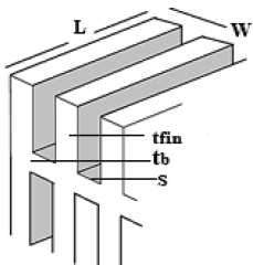
On a plate in the collector, with rectangular fins on both sides of the plate, with dimensions of the plate as shown in the above figure, (See Fig. 2). Here, the area of the collector Acl, the area of the plate without fins, Aunfin , the perimeter of the base of the fin, p, the area of the base of the fin, AbI, the space between fins, s, and the number of fins, N, are determined by the following expressions,
The drag force is defined as,

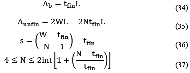
where, Vch, is the velocity of the channel, fapp the apparent friction factor (for laminar flow, which depends on the value of the Reynolds number, Re Dh ), Kc the apparent contraction factor, and Ke the expansion factor apparent, which are defined as follows:
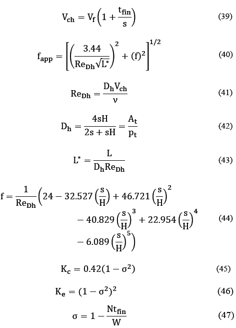
Re Dh is the Reynolds number for the hydraulic diameter of the channels that form the fins (Dh), and ν the viscosity of the fluid that circulates through the collector (air). The value of the heat transfer coefficient, h, is cleared from the Nusselt number, using the following equations,
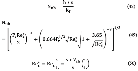
being, Pr the number of Prandtl, which for the air is approximately 0.7. The parameter kf is the thermal conductivity of the air, and Res the Reynolds number for the spacing s, between the fins of the plate. On the other hand, θmax depends on h and Ap, the heat transfer area, which is equal to:

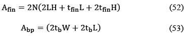
being Aunfin, Afin, Abp, the area of the plate without fins (eq. (35)), the area of the fins (eq. (52)), and the area of the base of the plate on which the fins are mounted (eq. (53)), respectively.
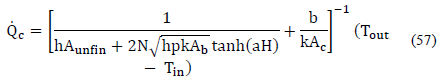
Now, using the global optimization method PSO (Particle Swarm Optimization), we will find the values of Vf, N, tfin, and H, which minimize Ns, for a desired output temperature value (θout), taking as fixed values B, θin, and kf. It should be noted that θmax can also be expressed as,
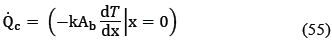
where R is the thermal resistance of the collector plate, understood as a heat sink. The product hAp, in fact, must be equal to said resistance, which can be determined from the thermal dynamics of the dissipator. In a flat plate solar collector with fins, at the base of each fin (with base area equal to Ab) it is satisfied that,
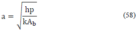
In other respect, the differential equation that governs the heat transfer in each fin is, in turn,
h being equal to the heat transfer coefficient of the air by convection (W/m2 K), and k the coefficient of heat transfer by conduction of the material from which the collector plate is made (W/m K). In a solar collector with flat plate and rectangular fins, whose length is equal to the length of the base of the plate, starting from the two previous equations, for a flat collector with N fins of constant transversal area, it can be demonstrated that, for the collector, the energy balance establishes that,
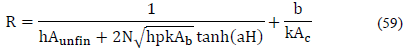
where b is the thickness of the plate, and a is defined by the following equation,
R therefore, is equal to,
3. Analysis of results
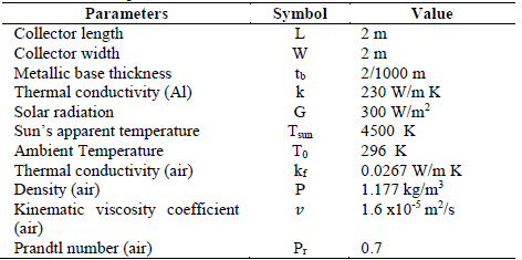
The parameters shown in Table 1 were considered for a collector with an aluminum plate, and a desired outlet temperature of 50°C. This temperature was selected, because it is required for grain drying applications, such as coffee or cocoa.
Starting from these parameters, and by means of a particle swarm optimization algorithm, PSO, we found the values for N, Vf, tfin and H, which minimize the entropy generation number, Ns (eq. (29)). The results of the minimization appear in Table 2. N represents the number of fins by one side of the plate in the collector. The total fins in the collector are 2N.
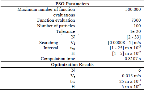
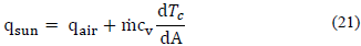
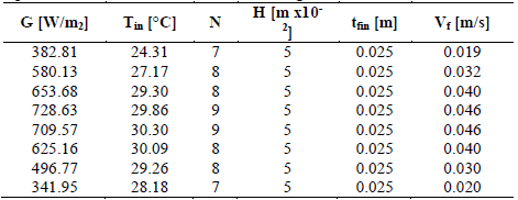
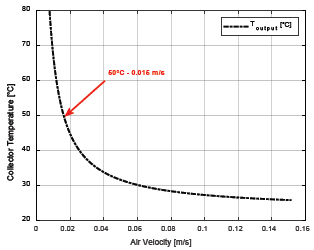
These results were obtained assuming an irradiance of 300 W/m2, with an input temperature of 23°C. With this, and the values of N, Vf, tfin, and H, the collector can reach an outlet temperature of 50°C. Nevertheless, this must be confirmed. From the energy balance in the collector (eq. (21)), it was possible to establish that, indeed, for parameters found, outlet temperature reaches 50°C (see Fig. 3). But irradiance varies during the day. For this reason, the optimization method must carry out tests with different values of irradiance and input temperature in the collector. Also, from eq. (21), the minimum air velocity required to reach 50°C at the output of the collector was fixed. We ran the optimization algorithm again. The new results are summarized in Table 3.
Source: The Authors.
Figure 3 Outlet Temperature variation with air velocity (Tin, 23°C; G, 300 W/m2, N=12, H=5mx10-2, tfin=25x10-3)
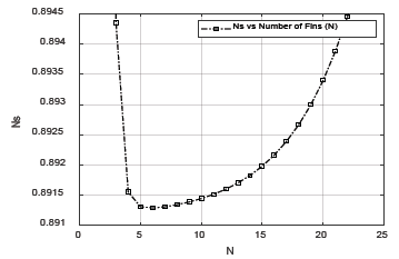
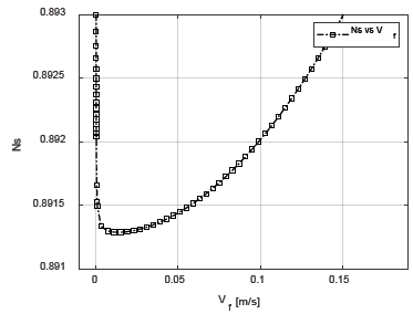
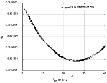
The variation of irradiance implies variations in the number of fins, N, and the velocity of the air, Vf, while H and tfin remain constant. With the objective of examining the variation of entropy generation with variable numbers of N, Vf, tfin, and H, and for complementing the information of Table 3, Figs. 5-8 shows the variation of the dimensionless value of the entropy generated (eq. (29)), for variant values of these parameters, respectively.
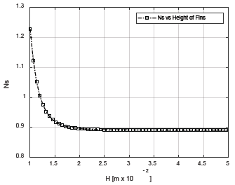
The analyses performed allowed us to appreciate how the variation of the entropy generated in the collector, is minimized for a specific number of values of N, Vf, tfin and H. For N, Vf, and tfin, there is a value for which before and after the same, the entropy generated is increasing. Note that, for each parameter, Ns have a delimited range where its value is minimum, except for H. The entropy generated is stable for values of H greater than 2.5x10⁻² m. Variation of fin thickness shows the minimum contribution to Ns respect to the contribution of N, H, and Vf, although they have an absolute minimum near to 25mm.
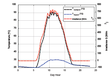
A typical curve of mean irradiance is shown in Fig. 4. The outlet temperature was determined from eq. (21).
Source: The Authors.
Figure 4 Irradiance and environment temperature (Tin), for the month of March in Bucaramanga, Colombia. (Toutput was calculated from eq. (21), with N=6, N=12, H=5mx10-2, tfin=25x10-3)
Source: The Authors.
Figure 5 Variation of entropy generation number, Ns, respect to the number of fins, N, in the collector plate.
Source: The Authors.
Figure 6 Variation of entropy generation number, Ns, respect to the air velocity Vf.
Source: The Authors.
Figure 7 Variation of entropy generation number, Ns, respect to the thickness of the fins, tfin
Source: The Authors
Figure 8 Variation of entropy generation number, Ns, respect to the height of the fins, H.
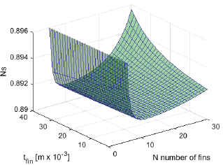
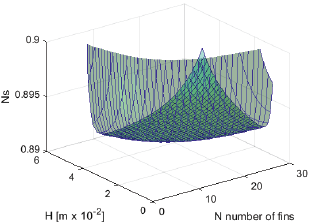
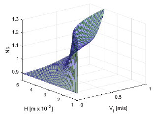
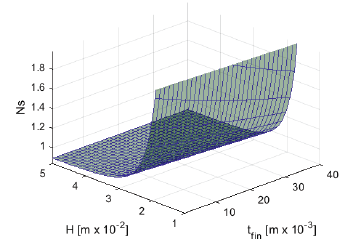
Figs. 9-14 show the variation of the entropy generation number (Ns), for the combinations of two geometric parameters of the plate in the collector: N and Vf, N and tfin, N and H, Vf and tfin, Vf and H, tfin and H. These figures reveal that the most influential parameters are the number of fins (N), and the air velocity (Vf). In each pair of combinations, these parameters are dominant. When N and Vf and N and tfin vary, the dominant parameter on the variation of entropy generated is N, in so much that when N and H vary. By varying Vf and tfin and Vf and H, the dominant parameter is Vf. When tfin and H vary, the dominant parameter is H. An optimum value for air velocity must be small (minor than 0.05 m/s), but not near zero.
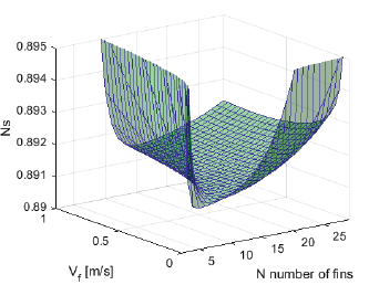
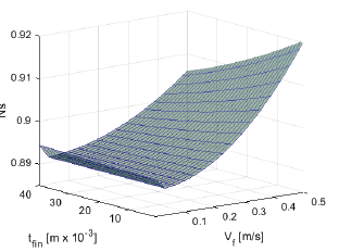
The same consideration applies to the number of fins. A small number of fins (between six and nine) produces small Ns. A collector without fins is less thermally efficient evidently than a one with fins.
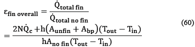
The efficiency of the collector plate was calculated using the ratio of the plate heat transfer with fins to plate the heat transfer without fins. We analyzed the effects of N, Vf, tfin, and H. The following equation was used being A no fin equal to the area of the collector plate (without fins), [28]
For variations of Vf and tfin, the global efficiency of the fin was found to be constant (about 1.3). This indicates that amplifying Vf or tfin does not improve the collector heat transfer performance. For variations of N between 2 and 30, the global efficiency changed between 1 and 2. For N equal to 7, the global efficiency was equal to 1.3. A similar situation occurs with the variation of H between 1x10⁻² m and 5x10⁻² m. For these values, the global efficiency changed between 1 and 1.23. On average, this collector efficiency was 1.3, which means that the performance of the collector heat transfers with added fins, is about 30% better than that of a collector without them. This effectiveness could be increased by increasing N, but this directly affects the energy quality, because increasing N implies rising the entropy generation rate.
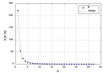
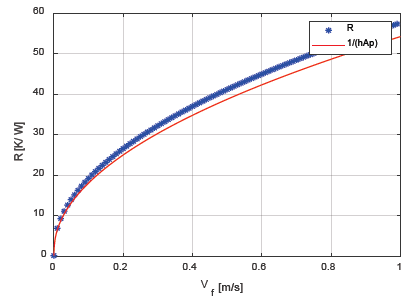
From simulations, the definition of R, the thermal resistance of the collector plate, with rectangular fins (eq. (59)), and the inverse of the product between the heat transfer coefficient, h, and the effective area of heat transfer, Ap, (hAp)-1, where compared. While increasing values of N, tfin, and H, reduces the value of R, increasing values of Vf increases R. Since Reynolds’s number gets larger with Vf, the rise of R with Vf is associated with the turbulence of the airflow. The values of the thermal resistance of the plate in the solar collector are comparable with the product (hAp)-1, for different values of N and Vf. For variations of H, R and the product (hAp)-1 maintains a constant difference of 0.5 [K/W]. For increasing variations of the thickness, both, the product (hAp)-1 and R-value decrease, but their slopes are different. Therefore, taking into account the detailed differences, these values (R and (hAp)-1) could be interchangeable in the equations that model the system. Figs. 15-16 show the variations of R and (hAp)-1 with N and Vf. The design method for a solar collector that minimizes entropy generation rate is synthesized in Table 3.
Table 3 Synthesis of the design methodology for a solar collector that minimizes entropy generation rate
Source: The Authors.
4. Conclusions
Our data demonstrated that airflow velocity within the collector greatly influences entropy generation. Nonetheless, and to the best of our knowledge, this is the first work that considers such a variable. We found that non-optimum values considerably increase entropy generation at the collector.
Moreover, our simulation of the solar collector showed that plate effectiveness increases with the number of fins and their height, but this entails a considerable growth of entropy generation. Similarly, increasing flow velocity also raises entropy generation. However, it does not increase effectiveness.
As a test case of our methodology, we determined the optimal parameters for a flat-plate solar collector. We assumed a collector with an area of 4 m2 which receives a variable 200 and 700 W/m2 irradiance. Our workflow revealed that the collector must contain 18 fins with a thickness of 25x10-3 m and a height of 5x10⁻² m. These fins should be evenly split on each face of the collector. Our results are relevant for future developments of solar collectors. For example, the design shown can be used for grain drying processes.

