


 Inglês (pdf)
 Artigo em XML
 Referências do artigo
 Enviar este artigo por email
 Citado por SciELO
  Citado por Google
  Similares em
SciELO
Similares em
SciELO  Similares em Google
 Permalink
1. Introduction
It is not always possible to guarantee that the response of a built structure under real loads to be equal to that obtained from the numerical model used in the design process. From this situation, the following questions arise: How reliable is the proposed analytical model in representing the true behavior of the built structure? How can it be computed a reliability measure? How can the analytical model be improved to increase reliability? Many industries have tried to answer these questions, including civil (buildings, stadiums and bridges), mechanical (motors) and aeronautical (airplanes and satellites).
The research efforts on the subject are grouped in a field known as model updating. The goal is to define procedures to establish the correct mathematical model that represents the real behavior of a system from a finite element model (FEM) of the designed structure, and experimental data of the built structure. The problem is formulated as a mathematical optimization one, where the difference between the analytical and experimental response of the system is minimized by changing a specific characteristic of the initial model. The problem is solved by using either a classic or a heuristic computational technique. Then, the updated model can be used to reliably predict the behavior of the system to future loads.
The mathematical model corresponding to update a FEM of a structure is established in terms of an objective function, design parameters, design variable and constraints. The objective function is written from the differences between analytical and experimental structural responses (static, dynamic or both), being that more than one response type could be used. In that case, a linear combination of weight factors is frequently employed to account the contribution of each parameter in the updating process. The chosen values for the factors influence the optimization process, and its definition generates discussion between researchers. Hao and Xia [1] claim that the weight factor values should be chosen by considering the quality of the data. In that sense, the factor for natural frequencies is generally greater than that assigned to mode shapes, as their computation presents less noise level. Concerning the design variables, the process modifies specific properties in the original FEM (such as material properties, element or support stiffness, etc.) to create a new and better one. Design parameters such as the geometric configuration of the structure do not change during the optimization process. Constraints are traditionally related to an allowed range of values for the design variables.
However, to carry out a correct updating process it is necessary to consider some issues incorporated in the problem:
The selection of the numerical technique to solve the optimization problem. Two approaches are generally followed: gradient-based and heuristic based philosophies. However, determining which philosophy is better requires much further analysis.
The definition of the structural response parameters that arise from the objective function and how to combine them. Schlune et al. [2] shows that the combined use of static and dynamic parameters can improve the updating process. Jin et al. [3] proposed a multi-objective problem to tackle the problem associated with the definition of the weight factor. Zapico [4] announced that only a few parameters are responsible for the differences between numerical and experimental models, but that its selection is particular to each problem and cannot be generalized.
Multiple local optimums in the search space rise due to the presence of errors both in the measurements and the definition of the FEM. One solution is that by keeping multiple optimum solutions during the optimization, the specialist can decide on the real structural behavior, as in Zarate and Caicedo [5].
In the specific case of bridges, there are many applications of updating models to real bridges. Ren and Chen [6] used natural measured frequencies to update the Hongtang Bridge’s FEM, a multi-span continuous deck precast concrete highway bridge. The numerical procedure selected was the surface response method to reduce the computational cost involved in the computational process, which facilitates its implementation in the engineering practice. Zhang et al. [7] updated the Kap Shui Mun Bridge’s FEM, a cable-stayed bridge, because it was not possible to obtain a FEM that completely matched the experimental frequencies. Wang et al. [8] carried out the model updating of the Runyan Bridge, a long-span suspension bridge, using a two-phase process that included data from dynamic and static tests. Such a combination of data improved the quality of the model obtained. Ribeiro et al. [9] employed the energy-based modal assurance criteria, damping and genetic algorithms (GA) for the update of the Sao Lourenco’s FEM, a bowstring-arch railway bridge. The GA was selected as the optimization algorithm because of the presence of multiple local optimums in the search space. In this sense, GA were used by Xiankun [10] to update the Southbound Tongyang Canal Bridge, a prestressed concrete continuous box girder bridge, from natural frequencies and MAC criteria. Jaishi et al. [11] employed gradient-based optimization to update the FEM of a concrete-filled steel tubular half-through tied-arch bridge located in Xining (China). This brief review shows the application of model updating to different bridge types. However, there is not a framework to establish which model updating methodology is best.
To the best knowledge of the authors, there are few published researches on the application of model updating to Colombian bridges. Rodríguez-Calderon et al. [12] calibrated the FEM of the Puente Salgar’s bridge by trial and error using a static load test, mechanical tests, structural information and topography data. The error obtained was lower than 9.7% related to the vertical displacement measured in some control points on the bridge. Muñoz et al. [13] also reported a similar difference level when the above procedure was applied to the updating of the Portachuelo Bridge’s FEM. Maldonado et al. [14] calibrated the model of a post-stressed reinforced concrete bridge located in Bucaramanga from ambient measurements and a basic genetic algorithm. The errors between the measured and computed frequencies are lower than 10%. Avellanada et al. [15] computed the values of the tension magnitude in the bridge cables by a theoretical formulation and natural frequencies with errors in the measured tension of less than 2.5%. Marulanda et al. [16] applied model updating to the calibration of the Hormiguero bridge’s model in Cali. Later, this model was used with the goal of monitoring the structural health of the bridge. The reported measurements indicated that the bridge presents problems with vibrations. Viviescas et al. [17] calibrated the FEM of the El Ramo Bridge by modifying the Modulus of Elasticity for the different types of elements in the bridge. Natural frequencies were calibrated with errors less than 1%. This review shows the first attempt in the country to apply this kind of advanced procedure in real structures.
Currently, different finite element modeling software, such as Ansys, allow for the carrying out of model updating by incorporating computational routines of optimization algorithms. This paper presents the formulation of a procedure for updating FEMs for bridges through the specific tools in Ansys and its application to a real bridge in Colombia. The information to fuel the process comes from ambient vibration measurements and their processing to obtain the natural frequencies of the bridge. An analysis on the sensibility of the results to changes in some parameters of the structure is reported.
2. Updating finite element models (FEMs) with Ansys
As for solving any optimization problem in engineering, updating the FEM of a structure requires the coupling of computational routines for: i) modeling the behavior of the structure (with known properties) under specific inputs (defined load systems); ii) considering the formulation of the mathematical model for optimization (assessment of both the objective function as well as the constraint assessment); and iii) solving the optimization problem by a numerical algorithm that is chosen based on the characteristics of the problem.
The above routines can either be already available or self-generated. The researchers in charge of the updating process frequently generate their own second routine while they use available software packages to carry out the first and third procedure. The approach implies that each package must allow for interaction with the others.
By using Ansys, it is possible to solve the updating model problem with only one software package (the three routines are coupled). In the following, the steps and issues needed to be considered in the updating of a bridge’s FEM are presented (see Fig. 1). However, it is worth mentioning that each bridge type requires some particularities, which will be discussed later in this paper. Additionally, there exists computational requirements to be satisfied.
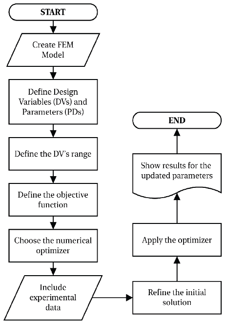
The first step of the methodology consists of implementing the FEM for the bridge from the one created in the structural design phase. This typically includes defining geometries, loads, types of elements, supports, mesh, the numerical procedures to determine the static and dynamic responses, types of contacts, simplifications, etc. If the updating is to be carried out after the construction of the bridge, it is recommended to verify the values for some properties used in the model, and to perform inspections to look for differences and damages in the structure. The definition of the characteristic model is very important as it is a source of numerical errors as shown by Humar [18]. Errors can cause the optimization algorithm to compute with the wrong design variables and therefore not converge to the correct model. However, uncertainties analysis could be considered during the process
From the model, the user needs to define which parameters are reliable (design parameters, DP) and which will be allowed to change during the optimization process (design variables, DV). Commonly, DPs correspond to the geometries of the model, types of elements, mesh, loads, supports, contacts between elements, and others. In the same way, DVs correspond to properties of the material in the systems including elastic modulus, shear modulus, strength compression, and strength tension. Different types of elements can have different values for the same property, e.g. elasticity modulus for the beam, piles, slab, etc. It is important to mention that there is not a global rule to define the above model characteristics, as this depends on each bridge. Concerning the number of DVs, n, it ranges between 1 and 100. However, as n increases, the complexity of the solution search space also increases, making it harder to find a solution and raising the computational effort required for the optimization process. Updating is an iterative process where each iteration is necessary to assess the structural response to compare it with the experimental one, resulting in a range of 100 to 10.000 models.
The following step is to define the upper and lower values for each design variable. A wrong selection of the range implies that the optimization algorithm will fail in the search for the correct values. If after the application of the updating, results show any variable with values close to the extreme ones, it is recommended that the procedure be executed once more with an increased range for the DV.
Ansys provides a generically objective function corresponding to the minimization of the difference between the available experimental data and the numerical response of the model as given in Eq. 1.
SVs is a type of structural response, such as displacements or natural frequencies. This equation considers the total error as the sum of the contribution of each individual error for the SD with the weight factor equal to one for all cases. In addition, Ansys has the ability to transform the problem into a multi-objective one, where an objective is defined for each SV. The main issues related to the definition of the objective function are:
The nature of the dynamic parameters used. For example, the use of only natural frequencies can produce difficulties in locating property changes in specific sites, as they are a global parameter. To illustrate this point, think about a simple support beam divided into six uniform, one-dimensional, finite elements. If the DV corresponds to the modulus of elasticity in each element, then a change in this DV for elements symmetrically located around the center of the beam will produce the same natural frequency changes. The problem can be solved if measurements of vertical displacement are included. However, this is the most used parameter for shaping the objective function. Therefore, it is required the combination with local parameters, such as mode shapes.
Sensitivity of the response parameters to the changes in the DVs defined for the problem. If these changes are minimal, they could be masked by errors in the experimental data. Ansys allows for the carrying out of a sensibility analysis to these variables. This part is so important because in this type of problem the changes generated in the SV due to variations in the DVs could be minimal. This increases the flatness of the search space and the presence of more similar local optimum, increasing the difficulties of the optimization process to find the optimal solution.
The quantity and quality of information plays a very important role during the updating process. Noise in measurements and incomplete dynamic information raise the complexity of the search space, which makes it highly multimodal [19]. The consequence of this is that it becomes impossible to find a FEM that completely matches the experimental data. It is important to mention that as the formulation is multi-objective, Ansys will provide different solutions respective of the quality for each SV. This happens due to the presence of noise in the measurements, lack of information and the possibility of producing the same structural response from several changes.
The math equation structure. Proposing a correct function can ease the updating process by using the less complex search space.
The point now is about which optimization technique will be used. Ansys allows choosing among screening methods (SM), non-linear programming with quadratic Lagrangian (NLPQL), mixed-integer sequential quadratic programming (MSQP), adaptive single-objective optimization (ASO), adaptive multi-objective optimization (AMO) and multi-objective genetic algorithm (MOGA). The selection of the best algorithm depends on the type of system to be updated and the defined DV. In the case of bridges, all of them can be used, but for this research, the MOGA was tested due to its characteristics for dealing with multiple local optimums. MOGA creates the Pareto Front by a method of classification of solutions improved for decreasing the computational time of traditional methods. This type of algorithm does not require the computation of any derivatives. Ansys defines the properties of the parameters of this algorithm, which affect the convergence process. In order to use it correctly, it is recommended that the user attend a previous lecture, such as [20] on how this algorithm works. It is worth mentioning that there is the possibility of using one’s own optimization routines, in Matlab or Phyton for example, coupled with Ansys, to analyze the bridge’s FEM. See references [21]. By doing that, it would be possible to improve the process search in terms of the obtained solution quality and the computational time required. There is not yet a consensus among researchers on which is the best optimization approach.
The next step corresponds to the determination of the information in the operational service of the bridge that will be used in the assessment of equation 1. Many proposals to do that can be found in the literature as part of the field known as health structural monitoring [22]. More specifically, this can be done by considering that only the response of the structure in terms of accelerations can be measured, a method called operational modal analysis [23]. This type of analysis does not require the measurement of excitation on the structure, as it avoids the use of excitation machines. It is important to mention that the definition of the objective function and the configuration of the experimental test must be made simultaneously to use correct and sufficient information that guarantee the reliability of the updating process. Therefore, if for example, the experimental information corresponds to dynamic parameters, it would be necessary to obtain information about the largest quantity of modes in the structure and in the main axes of movement.
The following step consists of defining the initial solution to start the optimization process. In the practice, this can be made by generating random values in the range of allowed values of the DV. The initial values assigned for the DV can affect the result, thus its definition has to be made with criteria. Ansys uses design of experiments to sample the search space more effectively. However, it is possible for it to be heuristically defined by the user and to be introduced manually in Ansys.
The optimization algorithm stops its execution when a maximum of iterations is reached. After that, the user responsible for the updating process has to do a results analysis to decide if the solution is correct. It is possible to assess the results’ quality by computing the error between experimental and updated numerical values.
In conclusion, it is important to mention that the calibration permits the improvement of the FEM for the linear range, and that this procedure can be used with small changes in the process of updating other structures. In this paper, the commands to use in Ansys are not reported.
3. Application of updating models to a Colombian bridge
The process presented in section 2 is applied to the calibration of the finite element model (FEM) for a Colombian bridge. The experimental setup corresponds to the testing of load and ambient vibration measurements obtained from [13]. In addition, the FEM in SAP2000 carried out in [13] was used to define the model in Ansys.
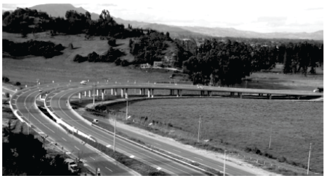
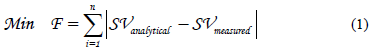
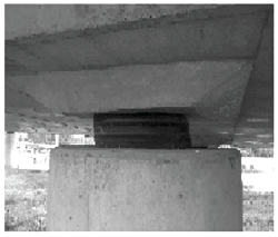
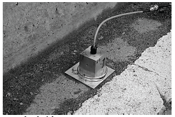
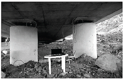
The Portachuelo’s Bridge located in Cundinamarca, Colombia, has an alignment that is vertical and a horizontal curve (Fig. 2). This is a slab bridge of 363.4m in length, uniformly distributed in 14 spans and supported by 13 piles formed by two reinforced concrete circular columns of a 1.4m diameter. Fig. 3 shows the cross section of the bridge. Each column in the top has low-damping elastomeric bearing supporting it, see Fig. 4.
Two finite element models were derived for this bridge as described in the following:
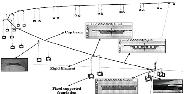
The first model corresponds to a 3D frame model based on the SAP2000 model reported in [13], which has rigid joints among elements, and a heading beam to connect the piles and the superstructure. Fig. 5 shows a conceptual representation of the FEM. The model uses the section presented in [13] in the way of frame elements, see Fig. 6. To simplify the model, it was necessary to define a very stiff link element between the connecting beam and the isolated bearings. The density of this element is not assumed in the modal analysis. Release was assumed in the connection to consider the transmission of only vertical and horizontal loads through the bearings. Bearings are modeled by orthotropic frame elements with a circular section whose diameter is equal to that of the pile where it is located.

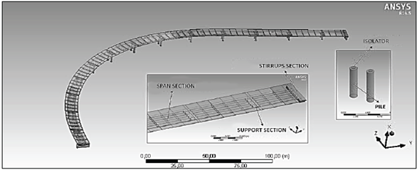
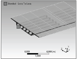
The second model is constituted by 186 and 187-type solid elements from Ansys (see Figs. 7 and 8), eliminating the requirement of either the heading beam or stiff links between the piles and the superstructure. The bearing is modeled with this element as well. Links among elements had to be different in function of the element type through elements named conta174 y targe170. The bonded link connected the elements in the superstructure to consider that two elements sharing the same face do not separate or present a relative movement between them. To define the best system, some tests with different contact types (rough, bonded and frictional contacts) were modeled to simulate the contact between the superstructure and the bearing.
The experimental test constituted of time history signals with the following characteristics:
Five accelerometers uniformly spaced through the bridge in 13 mobile positions (see Fig. 9). It is important to mention that the problem of locating the sensors in the structure is itself an optimization problem.
The reference accelerometer was located on the central pile (see Fig. 10).
Measurements are taken in operational conditions with a time window of 25 minutes.
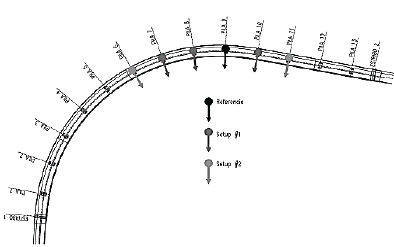
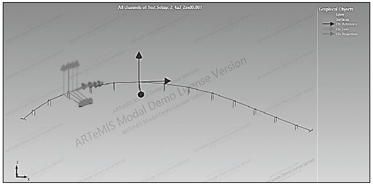
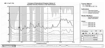
Signals were processed by using the Peak Picking method through the software ARTeMIS Modal Pro [24], (see Fig. 11). The software computes the singular value decomposition of the spectral density matrix functions from each setup of accelerometers configurations (Fig. 12). Then, it then computes the normalized average density spectrum. The natural frequencies of the system can be determined from this information, which can be used to update the finite element model of the bridge. This shows that numerical errors can be attributed to the experimental frequencies from the identification method.
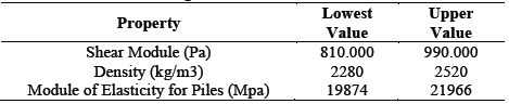
With respect to the updating process, the optimization design variables corresponded to the density of the material, the elastic module with the range of properties presented in Table 1. The SV states correspond to the modes 1 and 2 in the structure. The MOGA and the screening method will be used in the optimization process.
4. Results
Fig. 13 shows the average of normalized singular values of spectral density matrices obtained using the software Artemis, In addition, Table 2 presents the analytical frequencies for the two FEMs and the error with respect to the experimental values (in parenthesis). There exits difference until 16% and 12.3% between experimental and analytical frequencies for the first and second mode, respectively, which could be partially raised in the large mesh size. It can be observed that the model 2 with bonded-type contact produces the natural frequencies closer to the experimental ones. The second shape mode obtained from the model 2 with bounded contact is presented in Fig. 14.
Source: The Authors.
Figure 13 Average of normalized singular values of spectral density matrices for peak picking method.
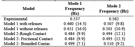
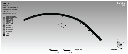
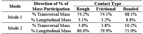
Table 3 reports the mass participation factor for model 2 by finite element analysis, observing that the contact type can be a source of error in the updating process. This shows the importance of a preliminary calibration of the algorithm by testing different conditions for the model. Model 2 with bounded contact will be used during the updating process.
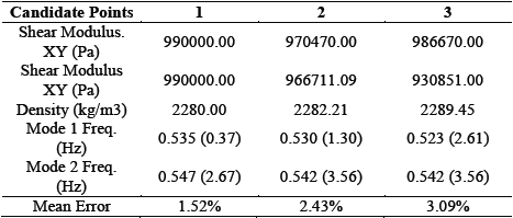
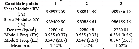
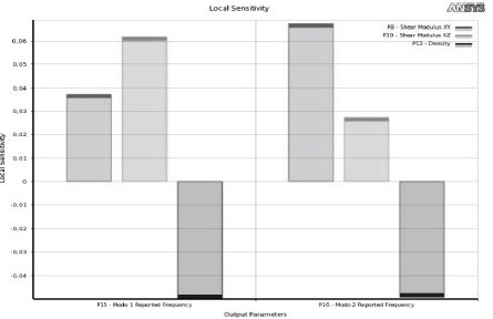
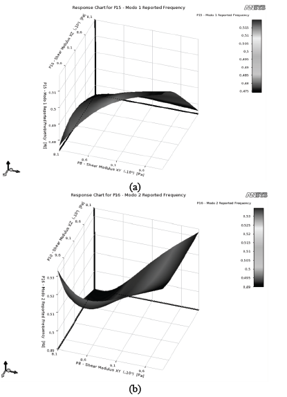
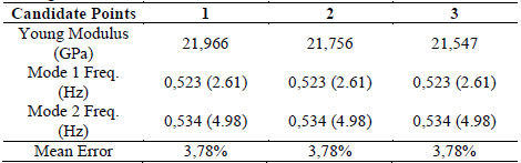
Tables 4 and 5 show the results for the application of the process, not considering the module of elasticity as a variable. As shown, the error with MOGA is less than 2% and it is better than that obtained with the screening method. Also, the three solutions provided for the algorithm present a low dispersion, which show that the algorithm converged adequately. Fig. 15 shows the sensibility analysis on the changes in the state variables (mode 1 and mode 2) due to a modification on the variable design. It can be observed that changes in the variables related to the bearing affect the modes differently. Nevertheless, density considerably affects both modes. In addition, Fig. 16 show the response surfaces for the variation of the natural frequencies to changes only in the shear module. It can be observed that the behavior of the surface is very different between modes, which means that it would be necessary to use both.
Table 4 Results from the screening method. Seeking P13=0,537 Hz and P14=0,532 Hz.
Source: The Authors.
Source: The Authors.
Figure 16 Response surface for the change of the (a) first and (b) second frequency with respect to the shear modulus in the XY and XZ planes.
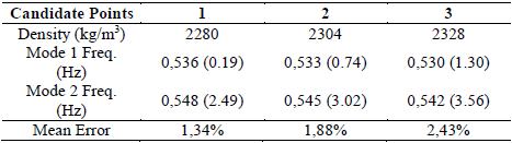
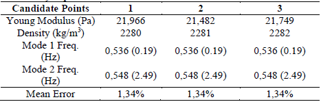
Results from the screening method are reported for the cases where the design variables are either from module of elasticity or density in Tables 6 and 7, respectively. The value used for the shear module in the bearings corresponds to the best value obtained in Table 2. The lowest mean error in matching natural frequencies when single design variables was obtained considering the density. The second mode presents more difficulties to be matched concerning the results obtained for the first mode. Table 8 presents the results when both variables (module of elasticity and density) are used. It can be concluded that the selection of the design variables plays a very important role, as different values were obtained for the errors compared to those in Table 2. In this case, the solution to the model corresponds to that reported in Table 7 for the error of 1.34%. The data dispersion was kept to be similar that mean obtained with a single design variable. However, the updating for the second mode was improved
Table 6 Results from the screening method (DV: module of elasticity in piles, seeking for P13=0,537 Hz and P14= 0,562 Hz. Source: The authors.
Source: The Authors.
Table 7 Results from the screening method (DV:density in piles), seeking for P13=0,537 Hz and P14=0,562 Hz.
Source: The Authors.
5. Conclusions
This paper presents the application of FEM updating methods to a bridge in Colombia. It established a procedure to develop this in Ansys as it is possible to update finite element models. The best results were obtained by using the screening method and by considering the young’s modulus and density as design variables. This shows that the process of updating requires an iterative process of defining the variable designs and considering the different optimization algorithms for the analyzed bridge. From the results, the initial errors were decreased from 7.0% to 1.34% for the first mode and from 9.2% to 2.49% for the second mode.
It is possible to use the proposed methodology in the FEM updating of other bridge typologies. However, each case presents its own characteristics; thus it is necessary to choose the best design variables and to define the modal data required to guarantee a correct updating process.

