1. Introduction
Augmented Reality’s (AR) main objective is to improve visual information perceived by the user by adding synthetic objects to the real space. Solving visualization and interaction problems is what motivates the creation of these environments.
In recent decades, a considerable number of applications have been proposed in medicine [1], education [2], museology [3], and entertainment [4] among others. Regardless of the application, AR systems follow a common process (Fig. 1) in order to accurately determine the position of the virtual object in the real space. In the registration step, the virtual information is aligned with the real information to create the augmented environment. A mixed environment such as this should be as coherent as possible so that misalignment be imperceptible during interaction. This is particularly important as AR can be used to support visualization tasks in critical applications such as surgical operations. In these cases, an incorrect registration of even two millimeters would be catastrophic. This situation is exacerbated by the requirement of real-time interaction, which implies the permanent calculation of accurate poses according to changes in the user’s point of view, within a reasonable time period.
Due to the great importance of a correct alignment of the virtual objects, different approaches have been proposed to reduce registration error. Nevertheless, many of these solutions require a lot of a priori information, or they only focus on guaranteeing correct camera calibration.
This article presents a method based on a clear methodology to reduce visual inconsistency in markerless augmented reality systems. It aims to calculate the best matrix in the affine space by relating 3D points in the world with their 2D projection in the video frame. In practical terms, it becomes a combinatorial problem because only four points- the n points extracted from the real scene-are needed to calculate the reprojection matrix. The use of the Ant Colony Optimization meta-heuristic is proposed to select the best points and so reduce the reprojection error. To the best of our knowledge, this is the first time that this meta-heuristic has been implemented to tackle the registration problem.
This article is organized as follows: the literature review is laid out in Section 2. The methodology followed is described in Section 3, and the details of the proposed method in Section 4. Experimental results are discussed in Section 5. Finally, conclusions and future studies are presented in Section 6.
2. Previous studies
The literature review presented below is organized into two sections. The first section reviews the different techniques reported that were used to register virtual-real information. The second section focuses on studies that address the reduction of registration errors.
2.1. Registration techniques
One of the most popular approaches for registration has been the direct placement of artificial marks into a scene. Due to its accuracy, many academic and industrial researchers have focused their attention on this kind of registration. In this technique, virtual objects are directly visualized over the marks. For this reason, it will be easier to determine the position for the superimposition of the virtual object if the mark can easily be recognized in the scene.
In the literature, different designs for marks have been proposed. One of the first works in this field was carried out in 1999 by Kato [5], who introduced the use of binary square marks. This technique is still used in works such as [6-8]. Other approaches highlight the advantages of embedded markers [9] and retroreflectors [10]. In general, using marks in the registration is advantageous in that it simplifies the process of feature extraction and pose calculation. However, such simplification implies the manipulation of the real environment by incorporating fiducials, which Schall [11] has called visual pollution. Additionally, an important limitation to take into account when using marks is occlusion. If portions of the mark are partially hidden, identification might not be carried out successfully, and the registration will fail. To overcome these limitations when using marks, an alternative approach consists of capturing the information for pose calculation from the natural characteristics of the scene.
Markerless registration [12,13] aims to identify features directly from the scene. The challenges that this method generates are associated with the selection of the features to be tracked, robustness when faced with rapid movements, and the calculation of the correct position for the superimposition of the virtual objects. As a result, much more work is needed to obtain the accuracy achieved by artificial marks. Nevertheless, this approach is suitable in environments where the use of marks is not feasible or desirable.
Finally, another set of studies focus on hybrid approaches, which combine visual-based methods with electromagnetic tracking [14,15]. The accuracy of this hybrid registration is achieved through the careful acquisition of the tridimensional coordinates of feature points by using 2D information extracted from the video sequence and sensors. The main disadvantage of this method is that it usually requires a prepared environment.
2.2. Error correction
Much effort and research has gone into the development of a technique accurate enough to achieve permanent visual consistency in the mixed environment, and robust enough to tolerate occlusion and changes in lighting. Calibration techniques model the relationship between the information captured by the camera and the real world. Some studies focus on analyzing an error by paying special attention to careful camera calibration [16], edge detection [17] or feature matching [18]. The use of heuristic methods has also been attempted for registration purposes. In [19], to determine the best pose, generic algorithms are implemented which minimize the 2D points of an image and the reprojection of its tridimensional points. The results show significant error reduction with a low associated computer cost. However, it requires the 3D model of the object used to render the visual information.
Considering the studies discussed above, the method used in this paper aims to overcome the limitations associated with:
Inaccuracy in the registration for long video sequences.
The use of a priori information, i.e., artificial markers and 3D models created beforehand.
The innovative element and main contribution of this work is the transformation of the registration problem into a combinatorial optimization problem, which is addressed by using a heuristic method. Below, we describe the methodology that was followed to create the AR system. The implemented methods are based on the Kanade Lucas Tomasi (KLT) algorithm for feature extraction and tracking, together with the calculation of affine reconstruction and reprojection matrices.
3. Methodology
A modular approach was followed for each process depicted in Fig. 1, without losing sight of the interrelation between modules. Each process is described below, although neither the techniques used for the extraction of features nor the optical flow method will be explained in detail since they have already been widely reported in the literature.
3.1. Feature extraction
Due to intrinsic or extrinsic factors, each step shown in Fig. 1 produces a certain degree of error. The error accumulated over the whole process can seriously affect the visual consistency of the AR system. Consequently, the method used for the extraction of natural features cannot be chosen at random. Neumann [20] states that a good characteristic is one which is tracked correctly along a video sequence. Therefore, when selecting relevant features, it is important to take into account that these must possess properties which guarantee stability and reliability.
In this study, the Shi-Tomasi method was chosen as the means of detecting the set of relevant features from the real world. This method uses eigenvalues to detect corners and proposes both a translation and affine model, which defines a point’s displacements and appearance changes.
3.2. Tracking
Tracking deserves special attention since it involves two main components, namely, modeling and identification. The former is used for the calculation of the pose and the latter is associated with 2D matching in image sequences. Tracking is considered to be the leading cause of error. This is because much of the information used in this stage comes from estimations, so minor errors can accumulate until the results generated become visually unacceptable in the mixed environment.
For the tracking, a pyramidal sparse optical flow method is implemented which determines the coordinates of where a feature appears in the frame i+1 regarding the features extracted in frame i. The selected tracker tolerates modeling for the relative movement of objects and the observer. Nevertheless, it does not model tridimensional movement of objects; it only models the image changes resulting from such movements.
3.3. Obtaining pose information
To determine position and orientation from features, a rotation and translation matrix is implemented that relates tridimensional points with their bidimensional projections. To calculate 3D points, the Euclidean coordinate system transformed into the affine coordinate system [21] is used. This has been widely employed for AR purposes because of its reprojection and reconstruction properties.
3.3.1. Reconstruction property
Consider an affine space defined by four non-coplanar points {P0, P1, P2, P3} ϵ R3 where P0 is the origin of the affine space, and {P1, P2, P3} are three basis points. The tridimensional coordinates [X Y Z]T of the extracted features can be determined in the affine space if the projections of each feature point and the projections of the four points defining the affine space {P0, P1, P2, P3} are known in two different views ([uj vj]T ; j=1, 2) (see eq. 1).
where projections [u j bi - u j bi ]T (j = 1, 2; i = 0, 1, 2, 3) are the affine origin points and the basis points in the two images.
In order to compute Eq. 1, two reference images (RI1 and RI2) need to be extracted from the video sequence. To reduce computational time, the feature extraction process is carried out only once in RI1 and then tracked with KLT to RI2. This process continues during the entire video sequence, where the old RI(k + 1) image becomes the new RI(k), and the new captured frame from the sequence video becomes the new RI(K + 1).
3.3.2. Reprojection property
This property calculates the projection [u v] of a point in an image k by taking into account its affine 3D coordinate, the base projection and the basis points (see eq. 2).
Due to the fact that in this proposition, the 2D coordinates of relevant features are obtained using the KLT tracker, the reprojection matrix will be used to compute the error by comparing the information obtained by the tracker with the information given by the matrix.
In this study, it is assumed that virtual objects will be superimposed on planar surfaces. So, when the system initializes, the user is asked to manually select four points to define the space used for the rendering of the virtual object. Note that in doing this, the four points used to define the affine space cannot be used because of the non-coplanarity restriction. The selection of these additional points is not a disadvantage of the method. On the contrary, it means that there is a greater tolerance of occlusions, since, if a point is hidden, it will be possible to estimate its coordinates from the reprojection property as explained in [22].
On the other hand, the definition of the basis points and the origin of the affine coordinate system is automatically carried out by using the method proposed in [22] consisting of a Singular Value Decomposition (SVD) of a matrix A which contains the coordinates of the feature points of the image and is situated in the center of mass of the feature points (see eq. 3).
Where [u j pi - u j pi ] (j=1, 2; i=1, 2,. . . , n) represents the projection of the 3D affine points in the two different views and [u j c - v j c ] (j=1, 2) is the center of mass of these projections. By SVD decomposition, the matrix A is expressed in eq. 4 in the form:
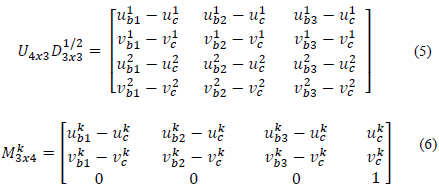
where U4x3, D3x3 and Vnx3 are the upper sub-matrices 4x3, 3x3 and nx3 of U, D, and V respectively. With this factorization, reconstruction and reprojection matrices can be formulated by eq. 5 and 6 respectively.
Finally, affine 3D points are obtained with eq. 7.
3.3.3. Error calculation
Considering that the reprojection matrix relates the n feature points with their tridimensional points (see eq. 8), and that matrix M3x4 can be used to obtain 2D projections of any point when its tridimensional coordinates are known, it is possible to calculate the bidimensional coordinates of the four points selected by the user to visualize the virtual object (see Section 3.3.2), if their tridimensional coordinates are known. This is carried out by calculating the reconstruction matrix from the factorization of the matrix A.
The reprojection matrix is used to calculate the error using eq. 9; where
 are the coordinates estimated with the matrix, and mki are the coordinates given by the tracker.
This study aims to find the best M3x4 matrix to minimize the error between the two data sets. In the described affine equation system, a problem becomes combinatorial when only four points are required to solve eq. 8. So, it will be necessary to find the best combination of 2D/3D point pairs among the set of extracted features which minimize the reprojection error. Consequently, eq. 9 becomes the target to be minimized, i.e., the mono-objective function for the optimization algorithm (see Section 4).
The justification for the implementation of a heuristic method is twofold:
A combinatorial optimization method enables the selection of only the best four points from the total set of extracted features.
Combinatorial problems are NP complete, which computing time is unacceptable in AR applications where real time interaction is required. Therefore, a meta-heuristic method enables an estimation of the optimal solution within an acceptable computing time.
4. The error reduction as an optimization problem
In 1959, the entomologist Pierre-Paul Grasse observed that termites reacted to certain stimulus. This had the effect of acting as new stimulus for the insect which produced it as well as for the colony as a whole. Grasse used the term stigmergy to describe this communication among animals of the same species. Stigmergy examples are evident in ant colonies where they move from and to a food source by depositing pheromones along the way. Other ants in the colony tend to follow the path where they perceive a strong pheromone track.
In Ant Colony Optimization (ACO), artificial ants move within a graph which contains the search space of the problem. Each ant is considered to be a possible solution to the problem. In the graph, the ant walks from node to node, building a solution, with the restriction that a node cannot be visited twice by the same ant. For each iteration, the ant chooses its which node to visit next depending on the amount of pheromone of the nodes available to be visited, where a higher degree of pheromone represents a higher probability of visiting that node. After finishing the iteration, pheromone values are modified according to the quality of the solutions built by the ants in each iteration.
Optimization based on ants was formalized as heuristic by Dorigo et al. [23], who described the following components for a model P={S,Ω,f} of a combinatorial optimization problem.
A search space S defined over a finite group of discrete decision variables X i
A restriction group Ω over the variables.
An objective function f = S → R 0 + to be minimized.
The generic variable X i takes values in{D i= {v1 i ,… vi (ǀDiǀ) } A possible solution s ϵ S is a complete assignment of variable values which satisfies all restrictions Ω. A solution s* ϵ S is called the global optimum if and only if f(s*) ≤ f(s)∀s ϵ S.
Using the ACO model, this study aims to calculate the reprojection matrix that will minimize the error between the estimated and the real coordinates. It will obtain, as accurately as possible, the two-dimensional positions of points where the virtual objects will be superimposed. To do this, the error is established as the objective function according to eq. 9. The decision variables are represented by the set of features tracked by KLT. In the present case, the model is expressed as follows:
● S = {X1, X2, …, Xi}; where i = 1 to the number of features, and X = (u, v)
Although, in the literature, several methods based on ant optimization have been proposed, we choose the Ant System (AS) method which is based on the permanent updating of the pheromones for all m ants that have built a solution. The total pheromone of each node is computed according to eq. 10.
where (1 - ρ) is an evaporation rate and
 is the pheromone track which is computed as indicated in eq. 11:
where Q is a constant and L k is the function to be optimized. The selection of the next node to be visited by an ant is a stochastic process given by eq. 12.
where s P is a partial solution, N(s P ) are the possible nodes to be selected and l is a node not yet visited by the ant k. Finally, η β il is obtained with eq. 13.
d ij is a function that describes the performance of the solution when the node j has been incorporated. For each iteration, the feature which is selected next will be the one which obtains the maximum value when eq. 14 is applied.
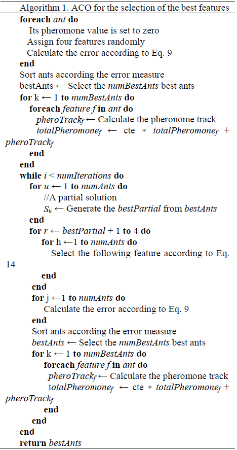
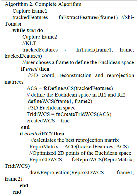
Algorithm 1 presents the methodology which clarifies how ACO should be used for the selection of the best features. The points (represented by an ant) are used to calculate the reprojection matrix which minimizes the registration error. This means that the matrix-according to ACO-accurately reprojects the extracting points. Algorithm 2 presents the complete algorithm for the whole process.
5. Results and discussion
In general, with ACO, an ant builds a solution by selecting 4 points from which the M3x4 matrix is calculated. This matrix is used to calculate the two-dimensional projections and then compare them with those made by the KLT tracker, by using the objective function described in eq. 9. When an ant presents a good solution (a low error), the four points it contains will have a greater probability (greater pheromone) of being chosen in the next iteration.
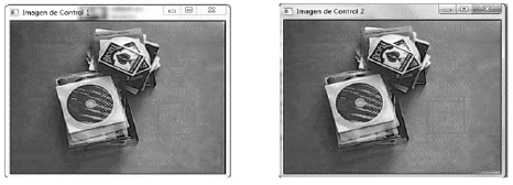
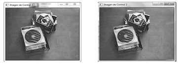
Tests were made with nine different video sequences, which were between 1710 and 3510 frames long. Results show an average of 0.5% of features lost along the nine videos. Note that the percentage of features which are not correctly tracked are of great importance. This is because the 3D coordinates of the features are obtained from the reconstruction matrix which was obtained from factoring matrix A. If some of these points are lost, matrix A, its center of mass, and the matrices U, V, D, will change. Therefore, projections and reconstructions will not accurately represent the structure of the scene. In the system proposed by this study, the Euclidean space is built from the four points manually chosen by the user. This task is carried out after the features are extracted. At the same time, the reference images (RI1 and RI2) are captured. They ar e used to define the affine space. Results of this stage are shown in Fig. 2.
To select the points that form the affine coordinate system, the user can use any mark that allows the four points in both images to be identified correctly. This pattern should be removed from the scene after the points have been chosen.
After the affine space is calculated, the reconstruction and reprojection matrices, the 3D coordinates of features, and the number of tracked features are computed. If the number of tracked features change, the process must be restarted. Otherwise, the 3D coordinates of the points forming the Euclidean space are obtained by relating the reconstruction matrix with the bidimensional coordinates chosen by the user.
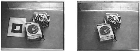
At time t = k, the reprojection matrix is calculated by solving the system of equations relating the 3D points of features to their corresponding 2D projections given by the tracker. Considering that the ACO method was used to determine the best reprojection matrix, it can be used to reproject the points of the Euclidean space with the lowest error.Results in the video sequences are shown in Figs. 3 and 4. The region used for registration is presented in red. Note that in the latter, the mark was removed after choosing the points which form the Euclidean space.
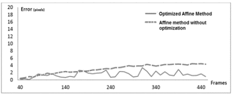
Tests were carried out where 15 features were considered within video sequences of over 350 frames. In the implementation of the optimized affine method, 200 ants were created, and 12 iterations were carried out. The error measures are plotted in Fig. 5 for 440 frames.
The comparison of the method proposed here with Pang’s proposition revels that the latter is more stable than the proposed one. However, the registration based on Ant Colony does not suffer from accumulated errors since it does not use previous positioning results. Moreover, the selection of the number of iteration and features is not a trivial step. Augmented reality systems run in real-time, so the optimization algorithm must converge before the processing of the next pair of frames. It is important to highlight that not every single frame was processed since the differences between two consecutive frames are not significant for the tracking process. Therefore, taking into account that ACO always finds a minimum, even if it is not the global minimum, the number of iterations was chosen as a stopping criterion, and was set to 12. For the present proposition, the number of features necessary for the convergence of the algorithm within the required time, and the number of iterations were both set empirically.
6. Conclusions and future studies
In this article, a methodology based on the Ant Colony Optimization (ACO) method is presented. ACO is proposed as a method to select the best set of points used to calculate the reprojection matrix that will generate the minimum error margin in the calculation of the 2D coordinates in which the virtual object is rendered. The selection of the best set of points is clearly a combinatorial optimization problem, which needs to be solved within a reasonable time frame because of the real-time interaction required in AR systems.
This proposal contributes to the improvement of visual alignment in markerless AR environments. The general performance of the method showed an average error of 1.49 pixels, with a standard deviation of 0.748. Moreover, an average reduction of 49.52% in the positioning error was obtained, compared to a non-optimized affine method. Although this method yields good results, new challenges emerge. Firstly, a feedback technique needs to be implemented to reduce the instability in the proposed method (jitters in Fig. 5). Second, the restriction of rendering on planar surfaces needs to be relaxed. Currently, we are working on the comparison of the proposed approach with other methods, notably, black hole. Similarly, we are working on the automatic setting of parameters.


