


 Inglés (pdf)
 Articulo en XML
 Referencias del artículo
 Enviar articulo por email
 Citado por SciELO
  Citado por Google
  Similares en
SciELO
Similares en
SciELO  Similares en Google
 Permalink
1. Introduction
A large variety of architectures exist in the family of robots, the most popular ones in the industry being parallel and serial manipulators. In serial manipulators, the actuators are located along their mechanical structure, generating an increase in the inertia that the robot must overcome to move; this means that the more actuators the robot has, the higher the charge on it is, affecting the stability of the entire mechanism. Additionally, each actuator increases the probability of generating an error of position and orientation of the terminal tool coupled to the mobile platform [1].
For this reason, parallel manipulators emerged, in which two or more kinematic chains support the mobile platform, increasing its stiffness, stability, load capacity and precision of position, orientation, velocity and acceleration of the final actuator, and the entire robot [2]. These advantages make these robots adequate for applications such as a) machining processes, b) mounting, c) manipulation, d) transport and e) storage [3].
Because of the importance of these robots, this paper addresses the kinematic, structural, and workspace analysis of a manipulator with linear actuators with consideration to two studies.
The first study examined the morphological synthesis of diverse solutions for kinematic chain structures for parallel manipulators of low mobility. This has been the focus of much research over the last few decades, resulting in four frequently used methods for morphological synthesis today: a) the screw theory [7], b) theory of displacement groups [8-10], c) theory of lineal transformations [11-13], and d) kinematic connections [1,14]. In this paper, the method of kinematic connections is used through the methodology proposed by Zhang [1]. Subsequently, the Chebychev-Grübler-Kutzbach criterion is introduced. The set of combinations of joints and links for the desired system and their linkage, omitting geometric details such as the link length and distribution, are illustrated. Finally, the development regarding the conceivable morphology is detailed, providing three linear degrees of freedom between the mobile and fixed platforms.
The second study examined the dimensional synthesis of the selected manipulator. To satisfy the demands for the design of these manipulators, the academic community has conducted various research that aims to establish methods involving numeric techniques of optimization [21,22], performance maps [23,24], and a maximum inscribed workspace [17], to guarantee a workspace that is as regular as possible. For the development of this study, the method of maximum inscribed workspace proposed by Lui [17] was used, incorporating an input transmission index [16]. Additionally, the cylindrical shape radius inscribed on the workspace intersection was exemplified. The geometric determination of the workspace for the manipulator was demonstrated using computer-aided design (CAD).
2. Methods
2.1. Preliminary restrictions of the manipulator
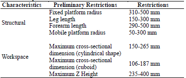
The border conditions or dimensional restrictions of the manipulator are the results of the settling of the workspace conditions, where the manipulator demonstrates its greater ability, and which have a low possibility of manifesting singular positions on its mobile elements. Table 1 shows the maximum permissible restrictions for the components of the manipulator, and the workspace dimensions according to the technical specifications of parallel manipulators of similar architecture that are used for commercial purposes [4,5].
2.2. Morphological synthesis
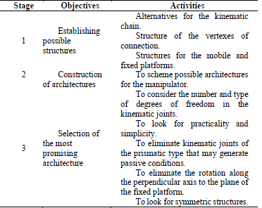
Table 2 shows the synthesis method of kinematic connections proposed by Zhang [1] for full isotropic parallel manipulators.
2.2.1. Design criteria
The structural conditions considered in the synthesis process are the following: a) manipulator with three degrees of freedom, b) fully-isotropic parallel manipulator, c) two known elements (fixed and mobile platform), and d) three parallel kinematic chains.
To determine the possible degrees of freedom provided by each kinematic chain in the manipulator, we evaluated the mobility of the kinematic chain using the Chebychev-Grübler-Kutzbach formula [15], along with the contribution of Tsai [15] to the passive degrees of freedom:
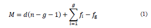
where M is the degrees of freedom of the kinematic chain; d is the degrees of freedom of the individual elements without restricting (6 in the spatial scenario and 3 in the plane scenario); n is the number of rigid bodies, elements, or links of the kinematic chain; g is the number of joints; f i is the number of degrees of freedom per kinematic pair; and f g is the number of passive degrees of freedom in the kinematic chain, and it may take positive values when degrees of freedom are available (not transferred to the terminal element) or negative values when there are additional restrictions to the movement.
2.2.2. Distribution of degrees of freedom per kinematic chain.
The different configurations of elements and joints that consolidate the kinematic chain can be determined by considering the different assumptions established to each of the parameters of Eq. (1). First, the equations that enable determining the number of elements in the kinematic chain, in function of the joints are defined:
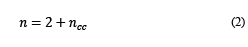
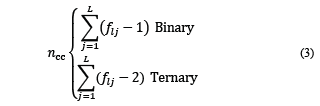
where n is the number of elements that consolidate the parallel manipulator, 2 represents the two platforms (fixed and mobile), and n cc is the set of elements that consolidate the parallel kinematic chains, which can be calculated in two different ways:
Considering each element as binary regarding the number of joints,
Considering that at least one element per kinematic chain is ternary.
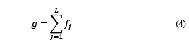
The total number of joints in the manipulator can be expressed as follows:
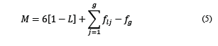
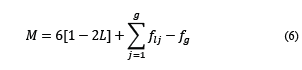
Substituting Eqs. (2)-(4) into (1) results in M for the scenario of binary elements (5) and ternaries (6):
By knowing the values of M, L, and f g , the total degrees of freedom provided by the joints in the kinematic chains that consolidate the manipulator can be determined.
2.3. Dimensional synthesis
The purpose of the dimensional synthesis is to determine the primary dimensions (or additional parameters) and initial position of a preconceive mechanism, according to the tasks that are developed. The term “primary dimensions” refers to the lengths of the links, whether they are binary or ternary. The defined dimensional parameters must generate a maximum workspace that accomplishes the following requirements [16]: a) regular form of the workspace according to the application, b) adequate required skill, c) compact configuration, and d) low-cost. Considering the criterion previously defined, the method of maximum inscribed workspace is used [17], incorporating an input transmission index [16].
2.3.1. Input transmission index
The function of the manipulator is to transmit the movement and force of an input link towards an exit link, guaranteeing the transmitted force along the kinematic chains, until the stated element can generate the dynamic equilibrium. Considering that the architecture of the manipulator is completely parallel and only considers one actuator per kinematic chain (considering active prismatic joints, but not the gravitational effects and the friction in the joints), the input transmission index is defined by [16]:
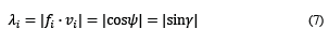
Where λ i is the input transmission index, γ is the angle of transmission, ψ is the angle of deviation, f i is the static force, and v i is the absolute velocity vector.
Fig. 1 shows the inverse transmission and deviation angles, as well as the static force of the coupler:
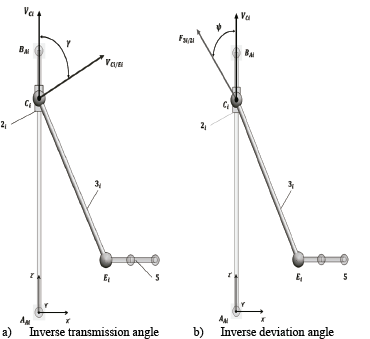
The angles γ and ψ, in Fig. 1 correspond to two criteria of the manipulator’s input manipulability. The first angle is known as the transmission angle, γ, and is defined as the lower angle between the relative velocity vector, v C/E , of the coupler element, and the absolute velocity vector, v C , of the input link, both obtained from the kinematic pair, C (Fig. 1 (a)). The other criterion consists of using the direction of the static force transmitted, F 3/2, from the coupler to the input element and the velocity of the connection point, v C; , the angle between them is known as deviation angle, ψ. In the analysed manipulator, the transmission and deviations angles are complementary (Fig. 1 (b)).
According to Tao [18], for systems in which the transmission of movement must be precise and at a high speed, the permissible values for the angle of transmission must be between 45 and 135o. Sharma [19] postulated that an angle of transmission lower than 20° is unacceptable for a mechanism of high velocity. Martin [20] asserted that mechanisms of general purpose must comply with a minimum angle of transmission higher than 40°. For the configuration studied in this project, the angle of transmission could not attain higher values than 90°; otherwise, the mobile platform would have surpassed the plane where the prismatic joints were located, which was not structurally possible to achieve. Taking as reference the previously mentioned, the input transmission index must not be lower than sin 45° ≈0,7. According to Liu [16] when the input transmission index is higher or equal to 0.7, the manipulator possesses an adequate relation of mobility or force. If within the maximum inscribed workspace, the positions of the kinematic chains of the manipulator are guaranteed, values lower to 0.7 will not be presented in the input transmission index, the mobile platform of the manipulator will have an adequate capacity to transmit movement and force, with a low possibility, and singular positions may result [16].
2.3.2. Design criteria
To determine the parameters, the method considers a cylindrical workspace of radius r0 and height h. From the cylindrical form obtained, an inscribed hexahedron of a similar form can also be defined. In Fig. 2 the mobile platform is considered to move over the horizontal plane with z=z 0 measured in regard to the framework of reference (OXYZ).
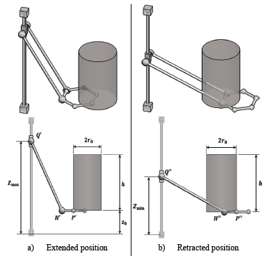
P’ represents the closer position of the center of the mobile platform with respect to the action line of the prismatic pair Q, while P” is the farther position. P’H’Q’ and P”H”Q” correspond to the kinematic chain orientations when the center of the mobile platform coincides with the borders of the cylinder. In Fig. 3, the orientations that can test the kinematic chain are illustrated according to the extreme positions the mobile platform may reach.
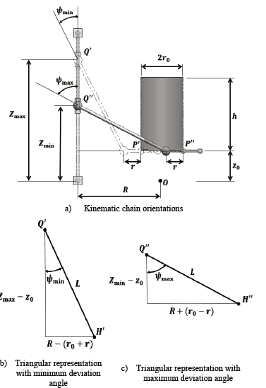
From Figs. 3 (b) and (c) the following relations are obtained between the dimensional parameters of the manipulator:
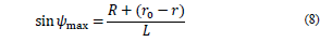
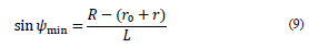
With the aim of establishing a technical condition and structural reliability between the maximum and minimum deviation angles, these are related to the maximum opening angle (in practical terms, the spherical joints have a permissible interval of values for the opening angle between 15 and 30°) that enables the spherical joint Ci, of the form
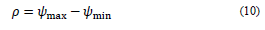
If the deviation angles are specified, the dimensional parameters L and R-r can be determined, using Eq. (9) and (10), in the form
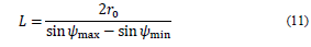
Under the same considerations, in Figs. 3 (b) and (c), the range of movement can be determined in the prismatic joints, and it corresponds to the defined height for the manipulator’s workspace through the equations.

2.4. Jacobian analysis of the manipulator
The Jacobian matrix of a parallel manipulator relates the velocity of the moving platform
 and velocity present in the active kinematic pairs
 [1]. The analysis of the Jacobian matrix is used to determine the manipulator’s stiffness matrix, which represents the resistance of the manipulator to the external forces applied to the mobile platform, assuming that the elements or links are rigid. Similarly, it represents the mechanical advantage of the manipulator associated with the capacity to transfer the forces from the linear actuators to the mobile platform [25]. Furthermore, the condition number (which is a measure of the sensitivity of the solution of a reversible matrix to the changes that its components can undergo) of the Jacobian matrix can be used to determine the manipulator's dexterity, which is an important kinematic factor that affects the accuracy of the speed and the dead load of the mobile platform [25,32].

then
Expanding Eqs. (15) and (16) for the three vector loops, we obtain
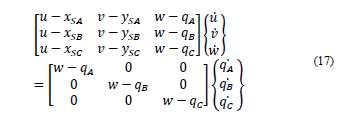
In which
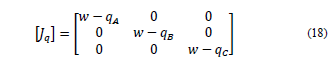
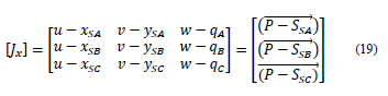
The Jacobian matrix can be expressed as
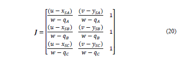
In which
2.4.1. Manipulator’s stiffness matrix
Let 𝝉=[𝜏1,𝜏2,𝜏3,⋯,𝜏𝑛]𝑇 be the vector of motor forces or torques that act on the manipulator and Δq= [Δq1, Δq2, Δq3,…, Δqn]T the vector of joint displacements. According to Tsai [15], the vectors t and Δq can be related by the equation
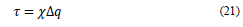
In which 𝜒=diag [𝑘1,𝑘2,𝑘3,⋯,𝑘𝑛, ] is a diagonal n×n matrix of the stiffness coefficients for each of the kinematic chains.
The resultant force of the mobile platform is related to the vector of motor forces or torques that act on the manipulator following the equation
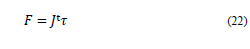
In which J t ,is the transposed Jacobian matrix.
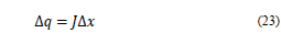
Joint displacements are related to linear and angular displacements (Δx= [Δx, Δy, Δz, Δ𝜙, Δ𝜃,Δ𝜓]T of the mobile platform following the Jacobian Matrix [15], as:
Substituting Eqs. (21) and (23) into (22) we obtain
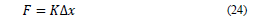
In which 𝐾=𝐽t𝜒 𝐽, is the manipulator’s stiffness matrix.
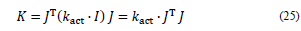
For the manipulator studied, the three kinematic chains were considered symmetrical and completely rigid; hence, we assumed that the only source of flexibility was concentrated in the active kinematic pair governed by the actuator [15]. Here, the stiffness coefficients were considered equal (𝑘a=𝑘b=𝑘c=𝑘act); thus, the stiffness matrix can be rewritten as follows:
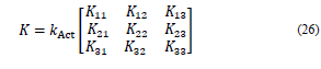
Using Eq. (25) in conjunction with Eq. (20), the stiffness matrix is obtained:
Because Eq. (25) depends on the Jacobian matrix, the stiffness also depends on the position in which the manipulator is; hence, the results obtained are instantaneous. The instantaneous stiffness associated with the mobile platform for each axis is associated with the components of the main diagonal of the stiffness matrix, as shown below:
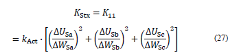
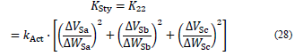
In which
KStx Instantaneous stiffness of the mobile platform in the x-direction.
KSty Instantaneous stiffness of the mobile platform in the y-direction.
KStz Instantaneous stiffness of the mobile platform in the z-direction.
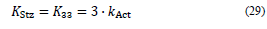
The previous results indicate that the stiffness along the z-axis depends only on the stiffness coefficient of the active kinematic pairs governed by the actuator for a given workspace.
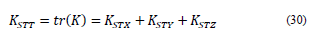
The total stiffness (K STT ) is determined as the trace of the stiffness matrix:
The stiffness of the active prismatic kinematic pair depends on many factors such as the mechanical components, power of the electric motors, and control system. The authors in [29,30] only considered the effect of the Jacobian Matrix in the stiffness analysis, which is why they assumed 𝑘act=1 kN/m. For most developed stiffness analyzes, Zhang [1] used a value of 𝑘act=1 GN/m, whereas Pashkevich [31] proposed a value for linear actuators as 𝑘act=100 MN/m. For the stiffness analysis developed in this study, the stiffness value for the linear actuators was considered as 𝑘act=100 MN/m, which represented an intermediate value for initial design purposes.
2.4.2. Condition index
The dexterity analysis is directly related to the condition index (CI) which is the reciprocal of the conditioning number Eq. (31) of the Jacobian matrix [16,33].
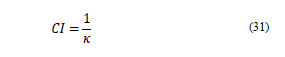
where k is the condition number, which is determined by the multiplication of any of the rules of the Jacobian matrix and its inverse, that is
Another approach to calculating the condition number is in terms of the stiffness matrix and its eigenvalues:
In which
λ1 Maximum eigenvalue of the stiffness matrix K.
λ2 Minimum eigenvalue of the stiffness matrix K.
The condition index can have a value between 0 and 1, which enables the skill, manipulator’s isotropy level (the ability to transmit movement and static charge in all directions), and the remoteness of the manipulator of singular positions to be determined [33]. When CI= 0, the robot is in a singular position, at which it is considered to be in a state out of control [17]. When CI= 1, the manipulator is in an isotropic configuration.
3. Results
3.1. Viable morphologic structures
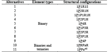
Table 3 shows the different alternatives or compound structural configurations for binary and ternary elements, achieving the defined requisites in Eqs. (5) and (6).
3.2. Morphological structure selected
The result obtained when the proposed methodology by Zhang [21] was implemented for the morphological synthesis process was that the structure of the manipulator that fulfilled the established design criteria was a
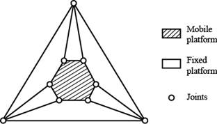
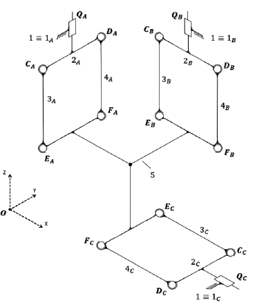
 type, which required the use of the structure of the mobile platform with binary vertexes (Fig. 4). The spatial kinematic scheme of the manipulator is shown in Fig. 5.
Source: The Authors.
Figure 4 Architecture for the parallel manipulator with binary vertexes in the mobile platform.
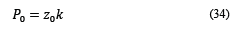
When the morphology of the manipulator was completely defined, the initial position of the manipulator was established (Fig. 6).
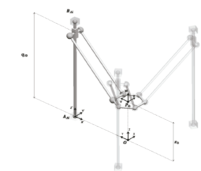
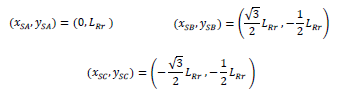
The independent variables were defined q1, q2, and q3, representing the position of the input link with respect to the axis Z’, which belonged to the fixed reference framework (AX’Y’Z’)i. Subsequently, the manipulator was considered to be in its initial position when the values of the independent variables q1, q2, and q3 were equal to qi0. Here, the reference framework of the mobile platform (PUVW) was located in relation to the reference framework (OXYZ) in the position:
3.3. Dimensional parameters of the manipulator
The dimensional parameters defined in Fig. 3 were calculated by the following preliminary dimensions of the workspace and the maximum and minimum deviation angles:
Cylinder radius: 𝑟0=75 mm,
Height of the cylinder: h = 200mm, ,
Maximum opening angle: ρ = 22.5°
Minimum transmission angle: γmin = 45°,
Maximum deviation angle: ψmáx = 45°,
Maximum transmission angle: γmáx = 77.5°,
Minimum deviation angle: ψmin = 22.5°,
Mobile platform Radius: r = 40 mm.
Considering the previous values and using Eqs. (11)-(14), the consolidated values in Table 4 were obtained:
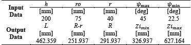
The resulting values were standardized, and the dimensional parameters of workspace were calculated again, which are shown in Table 5:
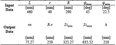
After the dimensional parameters of the manipulator were standardized, there were smaller variations in the workspace requested. Therefore, were used as the constructive dimensions of the parallel manipulator.
3.3. Stiffness analysis of the manipulator
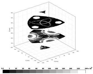
In this section, we study the behavior of total rigidity in the theoretical and maximum inscribed workspace. Fig. 7 depicts the horizontal cutting planes which were taken with z-values of 230, 280, 385, and 430 mm.
As Fig. 7 shows, the black areas are those with the lowest values in the total stiffness, while the white ones represent the highest values. The maximum stiffness was adjusted to a value of 2.5×10⁸ kN/m to obtain a better visualization of the results (although few points reach this value). These areas of increased stiffness coincided with the actuator’s arrangement in which the platform reached extreme positions within the maximum inscribed workspace. The lowest value reached was approximately 105 kN/m; thus, there were no critical points.
3.4. Dexterity analysis of the manipulator
Subsequently, the results obtained were analyzed for the condition number in the theoretical and maximum inscribed workspace. Fig. 8 shows the horizontal cutting planes, which were assigned z-values of 230, 280, 385, and 430 mm.
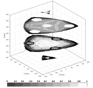
Figs. 8 and 9 show values of the condition number approximate to one in the central area of the maximum inscribed workspace, presenting values equal to one (isotropic configuration) when the mobile platform was located at and Px = 0 and py = 0.
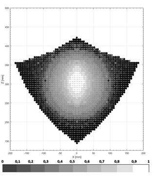
The white area represents high values of the number of conditioning (approximately one), which represents a configuration away from singular positions, while the black area represents the lowest (approximately zero). This zone of conditioning values approximate to one also depended on the position on the z-axis of the mobile platform; within this region, the best behavior of the conditioning number within the range of values for Pz between 210 and 420 mm was presented.
Considering the results obtained, the design workspace defined was considered to present values of the condition and stiffness numbers suitable for the operation of the manipulator.
3.5. Manipulator’s workspace
CAD was used to obtain the theoretical workspace, enabling the Boolean features with multi-solid bodies to be obtained. Fig. 10 (a) shows the theoretical and maximum registered workspace, in which the workspace design was located, a completely confined cylinder. These can be observed in detail in Fig. 10 (b), where the dimensions of a definite workspace are shown.
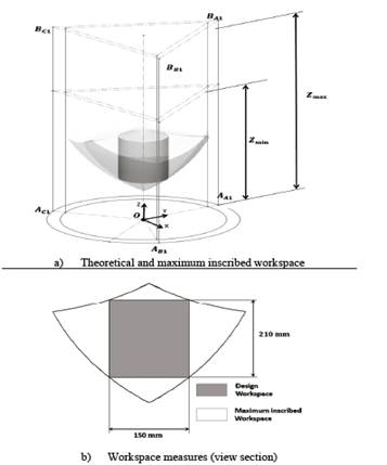
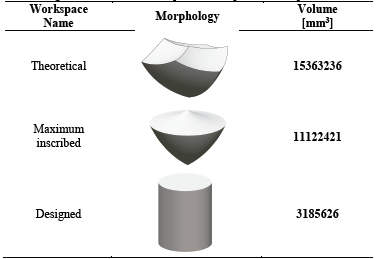
Table 6 shows the volumes of every workspace, achieved by the parallel manipulator’s design.
4. Discussion and conclusions
The proposed methodology for the morphological synthesis enables a significant number of solution alternatives to the kinematic chains to be used in the manipulator to be obtained. From the eleven possible topologies defined, the selection process led us to identify the configuration
 as the most promising and viable in terms of the established design criteria. Moreover, the dimensional synthesis, based on the concept of maximum inscribed workspace, enabled the dimensional parameters of the manipulator to be determined and to relate them directly with the proposed dimensions in the design criteria for the workspace. When the dimensional synthesis process was incorporated into the study of the input transmission index, the aim was to generate dimensional parameters in the manipulator which enabled an adequate relation between mobility or force in the manipulator’s mobile platform with a low possibility of determining singular positions. The stiffness and dexterity maps were obtained within the manipulator's theoretical workspace in some planes of interest. The results enabled the zones of the best behavior of the condition number to be identified, and no regions of the screen within the manipulator's workspace were observed that do not have utility service due to stiffness. This corroborated the fact that the workspace was designed with the values of the condition number and stiffness suitable for the operation of the manipulator. Finally, the geometrical determination of the manipulator’s workspace was conducted using computer-aided design to obtain the theoretical maximum inscribed workspace. The result of the study is useful for the design and application of parallel manipulators, as it addresses the process of morphological synthesis and dimensional process in a more practical manner. The methods used in this study can be applied to design other parallel manipulator configurations, in which linear actuators are included as input elements.

