


 English (pdf)
 Article in xml format
 Article references
 Send this article by e-mail
 Cited by SciELO
  Cited by Google
  Similars in
SciELO
Similars in
SciELO  Similars in Google
 Permalink
1. Introduction
The nuclear power gate valve, which is installed in nuclear and conventional islands in nuclear power station and power station auxiliary facilities, is a key component of the nuclear power plant system [1-3]. It is used to control medium pressure, temperature, flow direction, and flow rate while safeguarding the pressure vessel [4,5]. Clean, renewable energy (e.g., wind power) is rapidly becoming a priority as the national economy progresses; the market demand for nuclear power valves is expected to continually increase [6]. However, the high pressure and high temperature of the medium affect the strength and stiffness of the valve and thus drive down its sealing performance. To prevent structural failure due to deformation of the gate valve or any stress exceeding the allowable value, it is necessary to optimize the valve design by effectively analyzing its fluid-solid coupling.
The self-excited vibration generated by the nonlinear characteristics of the coupled spool movement and fluid dynamics create instability in the system, which in turn degrades performance and damages the hardware. Improper system parameters are generally the culprit. The pressure control valve design can thus be optimized according to its stability, as-proposed by Jian [7]. The stable boundary in the parameter space was determined via numerical simulation; the pressure control valve was then optimized by particle swarm optimization algorithm with the stable boundary as a constraint. Samad [8] analyzed the vibration characteristics of control valves of various shapes under the action of fluid exciting force to find that the vibration amplitude of a circular valve is lower than that of a flat or steep valve. Anelina[9] examined the stress and strain characteristics of a steam valve to find that changes in the time variable and non-uniform temperature field alter the local stress leading to metal fatigue.
There have been many other valuable contributions to the literature. Zhao et al.[10] used the finite element method to observe the effects of current on the dynamic characteristics and power loss of a high-speed solenoid valve; a decrease in driving current was found to deteriorate the high-speed solenoid valve open response, but the power loss can be reduced to enhance the valve’s energy utilization rate. When the appropriate current is maintained, it is possible to achieve an optimal balance between the opening response time and the energy distribution. Liu et al. [11] studied a butterfly valve installed in nuclear power plant pressurized water reactor circulating water systems; they established a computational fluid dynamics (CFD) model coupled with multi-phase, cavitation, and discrete phase properties. Numerical simulations were run to validate the coupling model according to cavitation, particle erosion, and flow coefficient characteristics. The effect of erosion was found to grow more severe as inlet pressure increases.
The gate valve has more strict sealing requirements than the butterfly valve and potentially higher medium pressure and temperature. Hu et al. [12] used a three-dimensional (3D) steady-state CFD method to simulate the conjugate heat transfer of an underwater gate valve. They combined various turbulence models and near wall processes to secure a k-ɛ turbulence model combined with low Reynolds number that well resolves the underwater conjugate heat transfer problem. Lin [13] and Huang [14] analyzed the resistance characteristics and internal flow characteristics of gate valves with different inlet speeds by CFD with 8 relative opening schemes. They found that the pressure coefficients of upstream and downstream gate valve pipes are basically the same at different inlet speeds, but when the relative opening is 2/8, the internal flow is chaotic and there is a high-speed jet flow. The pressure distribution on the valve is uneven, which severely affects its sealing performance.
Lin [15] adopted the Euler Lagrange simulation method to observe the gas-solid flow characteristics and erosion performance of horizontal and vertical gate valves. They found only slight differences between the gas flow characteristics and the flow coefficient in two cases for all open degrees and Stokes numbers. However, as Stokes number increased, the difference between the two kinds of trajectories grew increasingly obvious as did the differences in erosion distribution. Tomarov et al. [16] studied the corrosion resistance nuclear power plant valves, established possible cavitation conditions, and proffered realistic proposals to prevent valve damage. The gate valve is sealed through the valve seat and the gate, so the interaction of the valve seat and the gate markedly affects the seal.
Kolesnikov [17] and Wu [18] conducted finite element analysis on the fracture toughness of the valve body and the interaction of the contact between the gate and the valve seat. The contact force interaction must be small enough to prevent failure, but decreasing the contact interactions increases the risk of leakage - it is crucial to ensure the appropriate interaction force. Lin [19] applied a decoupling analysis method to establish a unified fluid solid coupling calculation model for the fluid structure interaction problem of air pressure seal valves. Based on the fluid solid coupling model, finite element analysis and CFD were applied to simulate the pneumatic seal valve for analysis.
Previous research on gate valves has mostly centered on vibration characteristics, sealing performance, and flow field analysis. However, the working medium, temperature, pressure, load, and other conditions related to the nuclear power plant valve’s high-temperature and high-pressure environment are more severe than those of the conventional gate valve. It is yet necessary to carry out fluid-solid thermal coupling to optimize the stability of valves utilized in nuclear power plants and other similar facilities. There have been relatively few studies on structural optimization and fluid solid heat coupling of high-temperature and high-pressure gate valves.
The deformation of the valve body as well as the size and distribution of the equivalent stress under test pressure and working pressure conditions were examined in this study by numerical simulation. The design variables, state variables, and objective functions were input to the optimization design module of the ANSYS Workbench to design the body structure. Fluid-solid heat coupling was utilized to investigate the temperature, deformation, and stress distribution of the gate valve under working conditions. The effects of various design parameters on the stress and deformation of the valve body were observed accordingly. The optimization scheme as-determined by this analysis was found to improve the stress and strain distribution of the valve body. The results presented below may serve as a workable theoretical reference for the optimization high-temperature and high-pressure gate valve designs.
2. Working parameters of gate valve
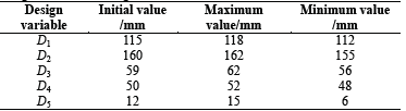
The parameter ranges of the primary loop of the PWR nuclear power plant are as follows. The working pressure is about 15 MPa, the inlet temperature of the coolant in the reactor is 280 ℃-300 ℃, the outlet temperature of the reactor is 310 ℃-330 ℃, and the increase of the import and export temperature is 30 ℃-40 ℃. The maximum average temperature difference allowed by the reactor coolant is 17 ℃-25 ℃ and the design temperature of the reactor is 350 ℃. The parameters of the gate valve designed in this study are listed in Table 1.
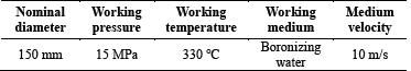
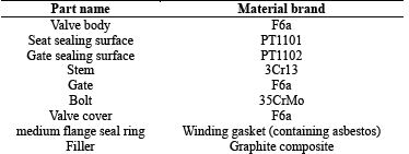
The GB/T12224-2005 states that the nominal pressure of the gate valve is the design pressure of 25 MPa. The material of each part of the valve is determined by the working parameters of the device (Table 2).
3. Gate valve calculation model
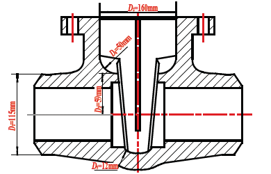
The outer diameter of the main channel of the gate valve initial model is D 1=115 mm, the outer diameter of the middle cavity is D 2=160 mm, the distance between the upper part of the seat and the central line of the main channel is D 3=59 mm, the chamfering size at the upper part of the seat is D 4=50 mm, and the chamfering size of the seat outer circumference is D 5=12 mm. These main body structure parameters are also shown in Fig. 1.
An effective 3D solid model of the gate valve accurately reflects the actual working conditions of the structure. The model should also be simplified to the greatest extent possible without sacrificing calculation accuracy.
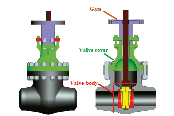
The pressure boundary of the gate valve mainly includes valve body, valve cover, and gate (Fig. 2). These three components, as a whole, bear internal pressure in the device. They are considered as a whole in the finite element model and the connection bolts between them are ignored. This allows for simplification of features that do not affect the overall performance of the gate valve while ignoring some unnecessary chamfering. The 3D gate valve model used in this study was drawn in Pro/E software as shown in Fig. 2.
4. Structure optimization design method
Structural optimization design is an efficient and convenient approach to analyses such as the one conducted in this study. First, x= (x 1 , x 2 ,...,x n )T is set as a vector in n-dimensional Euclidean space R n and f(x) as a pre-defined function[20-22]. Then the optimization problem proceeds by obtaining vector x under the constraint conditions ci(x) and cj(x), which makes the function f(x) a maximum (or minimum) value. This can be expressed as follows:
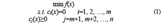
where f(x) is objective function, ci(x) is equality constraint condition, cj(x) is inequality constraint condition, x is design variable, f(x), ci(x) and cj(x) are two order continuous differentiable functions defined in space R n .
5. Coupling analysis model
5.1. Fluid-solid coupling calculation model
In this study, Workbench integrated in Ansys17.1 was used for fluid-solid thermal coupling of nuclear power valve. The fluid calculation domain was applied in Fluent software integrated with the fluid-solid coupling module in Workbench for numerical simulation. Static Structural software (ANSYS) was used to calculate the solid domain.
“Fluid-solid coupling” refers to the deformation or movement of a solid medium under the action of load. The deformation or movement in turn affects the medium, thereby changing the distribution and magnitude of the load acting upon it.
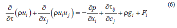
The finite element equation for fluid-solid coupling is:
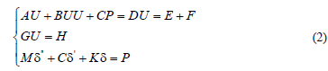
where U, P are the column vectors composed of all the nodes in the whole domain and U= [UVW]T.
Each coefficient matrix is superimposed by the corresponding coefficient matrix of all the elements in the whole domain:

where A e is the mass matrix, B e is the convective matrix, C e is the pressure matrix, D e is the loss matrix, E e and F e are volume force matrices, G e is the continuous matrix, H e is the boundary velocity vector, (″, (′, and ( are the acceleration, velocity, and structure stress column vector, respectively, M is the mass matrix, K is the stiffness matrix, and C is the damping matrix.
5.2. Temperature field calculation model
The temperature field is the temperature distribution of each part in the designated area; it also denotes the temperature distribution of each point in every moment. Solids and fluids conduct heat. The convection heat transfer phenomenon between a given fluid and solid is mainly attributable to the basic law of heat transfer.
(1) Heat conduction differential equation
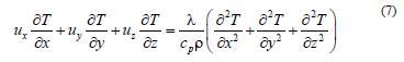
In the Cartesian coordinate system, for any point in the heat conduction object (x, y, z), the general form of the 3D unsteady heat conduction differential equation is:
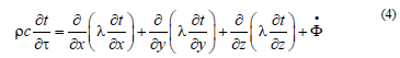
where ( is density (kg/m3), c is specific heat (J/(kg·K)), λ is thermal conductivity (W/(m·K)), and
 is the unit volume heating rate.
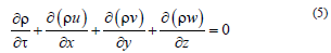
The continuous differential equation is:
The motion differential equation is:
The energy differential equation is:
6. Finite element analysis of valve body strength and stiffness
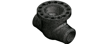
6.1. Grid division, constraint and load condition
The model is divided by an unstructured grid. The driving mechanism on the upper part of the connecting frame is not included in the calculation, as shown in Fig. 3. The grid partition software in ANSYS Workbench was used to divide the complex model and automatically encrypt its small parts. After division, the number of mesh elements was 266161 and the number of nodes was 444540.
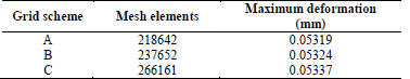
Mesh independence verification was performed on the solid domain under working pressure of 25 MPa. The maximum deformation was used as a criterion to judge the grid independence.
When the total mesh elements of the computational domains was 2.66 million, the maximum deformation was stable with further increase in grid number and the error was less than 1%. This meets mesh-independence testing requirements.
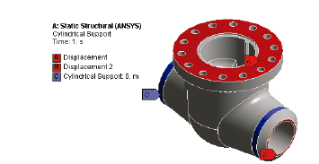
Axial displacement constraints were imposed on both ends of the valve body as they are welded to the pipe. The middle flange was connected to the cover of the valve and a vertical displacement constraint was applied to the end face of the flange. A cylindrical constraint was applied to the circumference of the two ends of the body to restrict the tangential and axial movement of the valve. The constrained body model is shown in Fig. 4.
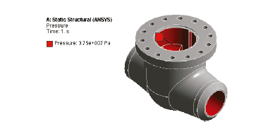
According GB/T13927-1992, the test medium of the shell pressure of industrial valves is usually water or air. The pressure of the system must reach (or exceed) the specified test pressure during a shell test to reveal whether the tested valve meets the given holding pressure performance requirements. According to the regulations, 1.5 times the nominal pressure (37.5 MPa) was taken as the test pressure. The test medium was water at normal temperature. The effect of the bolt preloading force and the weight of the valve body was ignored. The resulting valve body model after load application is shown in Fig. 5.
6.2. Finite element analysis of valve body strength and stiffness
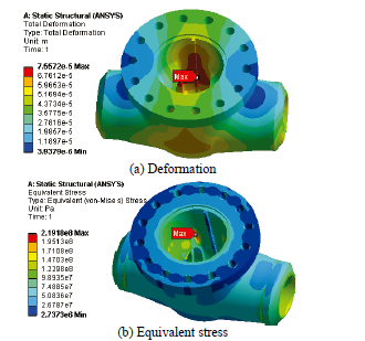
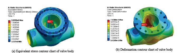
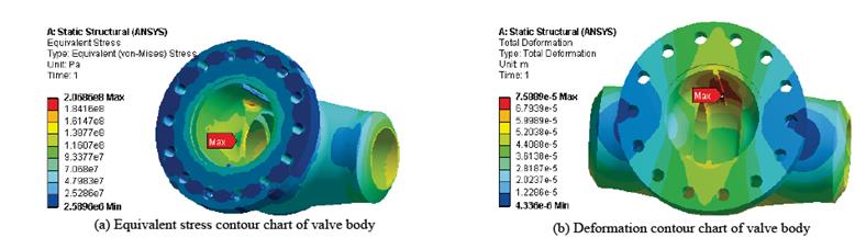
GB/T13927-1992 stipulates that the pressure wall experiences no visible leakage nor does the shell present structural damage in the test process. The cavity deformation body is usually controlled in the range of 0.001DN, otherwise the seal will be damaged by force deformation. The nominal diameter of the valve is 150 mm, so the allowable deformation is 0.15 mm. Under the experimental pressure of 37.5 MPa, after numerical simulation, the maximum deformation of the valve body was 0.076 mm and located on the sides of the middle cavity and main channel axis. The shape of the valve in this case is very simple (approximately cylindrical) and easily deformed, as shown in Fig. 6(a).
Source: The Authors.
Figure 6 Deformation and equivalent stress contour chart of valve body under test pressure.
The simulation results altogether indicate that the body structure meets the given stiffness requirements. As shown in Fig. 6(b), the maximum equivalent stress of the valve body is 219.2 MPa under the test pressure of 37.5 MPa and is located at the chamfer of the seat. There is a stress concentration at this point, and the allowable stress of the material is [s]=210 MPa, so the maximum equivalent stress of the valve body is beyond the allowable stress range of the material.
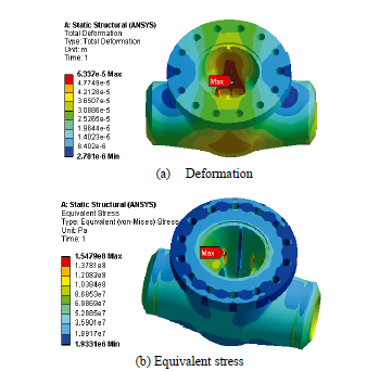
The deformation and equivalent stress of the valve body under the working pressure of 25 MPa were obtained as shown in Fig. 7. The maximum deformation of the valve body was found to be 0.053 mm and the maximum equivalent stress is 154.8 MPa, which meet the relevant stiffness and strength requirements. However, stress concentration persisted at the chamfer of the seat part at this point. It is necessary to improve the stress concentration of the valve body to ensure the optimal strength, safety, and economy of the device.
7. Optimization of valve body structure
7.1. Selection of variables and objective functions
As shown in Fig. 6, the maximum equivalent stress of valve body was identified at the chamfer of valve seat part. The stress at the seat part is large as is the deformation on both sides of the valve body, but the stiffness requirements are still met in this case. Therefore, the parameters of the valve seat and the section structure of the middle cavity can be considered optimization variables when optimizing the valve body structure.
The selected design variables must have an upper and lower bound. The ranges of optimum design variables in this study are shown in Table 4. The mass, which affects the economy of the device, was also set as a state variable.
The objective function is the expression of a certain performance index characterized by design variables. The proper objective function is directly related to the optimization of the valve body design, and is an expression of a certain performance index under the given design variables. The objective function must be selected properly to effectively optimize the valve body. Here, in order to make the equivalent stress of the valve body smaller than the allowable stress of the material, standardize the stress distribution of the valve body, and eliminate the stress concentration phenomenon, the maximum equivalent stress of the valve body was set as objective function. This allowed us to achieve the allowable stress range under the design and state variable constraints.
7.2. Effects of design parameters on valve body stress and deformation
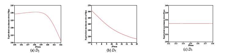
The response surface was optimized with the Design Explorer optimization module in ANSYS Workbench. The response diagram of the maximum equivalent stress of certain design variables on the valve body is shown in Fig. 8. The maximum equivalent stress of the valve body was found to first increase slowly with increase in D 2, then decrease rapidly once D 2 exceeded 159 mm. The maximum equivalent stress and amplitude decreased as D 5 increased. There was no obvious change in the maximum equivalent stress as D 1 increased; the contour indicates that it has little influence on the maximum equivalent stress of the valve body. The response graphs of other design variables are similar to that of D 1.
Source: The Authors.
Figure 8 Response diagram of design variable to maximum valve body equivalent stress.
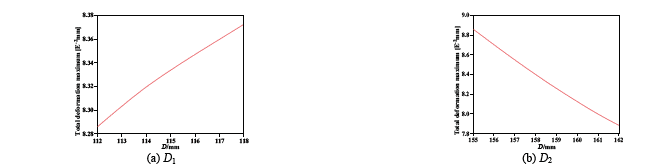
A response diagram for the maximum deformation of various design variables on the valve body was obtained as shown in Fig. 9. The maximum deformation of the valve body increased, though only slightly, as D 1 increased.
Source: The Authors.
Figure 9 Response diagram of design variable to maximum valve body deformation.
The maximum deformation of the valve body decreased as D 2 increased. The responses of the other design variables to the maximum deformation of the valve body were similar to that of D 2. Changes in design variable size appear to have little influence on the maximum deformation of the valve body and thus do not markedly affect the sealing performance of the valve.
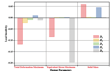
7.3. Design space and sensitivity analysis of stress intensity
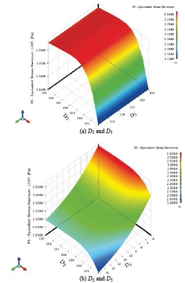
The maximum equivalent stress value of the valve body was minimized in this case due to the interactions among all optimization variables rather than the single function of a parameter. The solution obtained is the global solution within the constraint range. The calculated stress intensity design space is shown in Fig. 10 and the parameter sensitivity analysis is shown in Fig. 11. With in the specified design variables, changes in D 2 appear to significantly influence the maximum deformation, the maximum equivalent stress, and the mass of the valve body. Changes in D 5 significantly influence the maximum equivalent stress and changes in D 1 significantly influence on the mass.
7.4. Optimization results and analysis
The limitation range of each geometric parameter is listed in Table 4. The interaction of each geometric parameter of the valve on the maximum equivalent stress and the maximum deformation was determined through the objective function and response surface analysis (Section 7). The value range of each parameter was further clarified as discussed above and three optimization schemes were determined accordingly.
As shown in Fig. 8 (a), the equivalent stress and deformation are minimal when the diameter of D 2 reaches the maximum allowable value of 162 mm. As shown in Figg. 10 and 11, changes in D 2 markedly influence the maximum deformation, maximum equivalent stress, and mass of the valve body. The D 2 value of the three schemes was thus selected as 162 mm. The maximum equivalent stress also decreases as D 5 increases; D 5 was set to 12 mm, 14 mm, and 15 mm in this test. The value range of D 1, which significantly influences mass, was set to 112-118 mm.
Considering the matching of geometric dimensions, the value ranges, and the impact on the mass, the three optimization schemes were defined by 113 mm, 114 mm, and 116 mm values, respectively. Similarly, D 3 and D 4 were set to different values in an equilibrium relationship. The three schemes tested in this study were thus obtained by changing the values of D 1, D 3, D 4, and D 5. The variables that affect the strength of the valve body were optimized in the finite element program according to these three optimization schemes (Table 5).
Table 5 Comparison of the results before and after the improvement of the valve body structure.
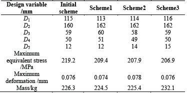
Source: The Authors.
Under the same material, mesh generation, constraint, and load experimental conditions as the initial design, three optimization models were analyzed by finite element method to obtain the equivalent stress and deformation cloud maps shown in Figs. 12-14. The original stress concentration point was substantially reduced and the stress distribution grew more uniform after the optimization. The maximum equivalent stress of the optimized valve body was located at the seat chamfering (Scheme 1) or the seat top (Scheme 2, Scheme 3). The maximum equivalent stress was less below the material allowable stress, which in practice would ensure a strong valve body satisfying the given work requirements.
The results before and after the valve body structure optimization are listed in Table 5. All the three schemes meet the relevant strength and stiffness requirements. The maximum equivalent stress of Scheme 1 is the largest and its maximum deformation and mass are the smallest among the three schemes. The maximum deformation of Scheme 2 is the largest; the maximum equivalent stress of Scheme 3 is the smallest and its mass is the largest. The maximum equivalent stress of the three optimization schemes was 4.5%, 5.2%, and 5.6% lower than that of the original scheme, respectively. Scheme 2 is a negative optimization in regards to maximum deformation. The maximum deformation of Scheme 1 was reduced by 2.6% and the maximum deformation of Scheme 3 remained unchanged. The mass values of schemes 1 and 2 were less than that of the original scheme, while that of Scheme 3 was higher.
The maximum equivalent stress, maximum deformation, and mass of Scheme 1 all decreased to varying extent compared with the original scheme. The maximum deformation of Scheme 2 and the mass of Scheme 3 comparatively increased, making their optimization effects inferior to those of Scheme 1.
7.5. Fluid-solid thermal coupling analysis of gate valve
The gate valve model was divided into an unstructured grid with 366033 units and 903515 nodes. A pressure of 15 MPa and temperature of 330 °C were applied to the inlet of the gate valve as a force of 80000 N was applied to the center flange bolt hole. The external surface of the gate valve was in contact with the air at this point and the heat transfer strength was low, so the convective heat transfer coefficient was set to 5 W/(m2·K). A fixed constraint was imposed on the left and right ends of the pipe.
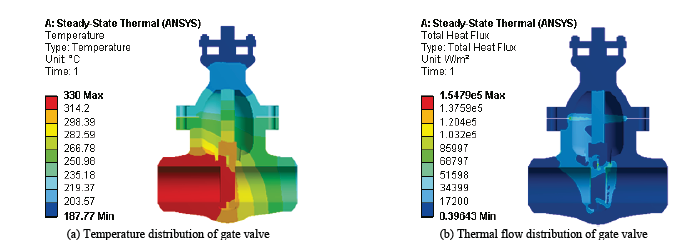
The gate valves in this setup are mainly composed of the valve body, flashboard, valve stem, valve cover, filler, and other components, all of which bear the fluid and temperature loads. The heat source is an important boundary condition for solving the temperature field; the heat source of the gate valve temperature field is the fluid. The temperature and heat flow distribution of the Scheme 1 gate valve is shown in Fig. 15. The temperature and fluid are basically the same as the inlet and gate are in contact with the fluid. The temperature of the other parts gradually decreased over the course of this analysis. The heat flow of the valve seat and the middle flange was large and the temperature gradient was also large, which caused substantial thermal stress.
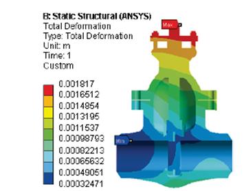
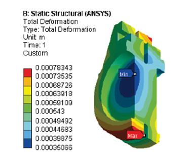
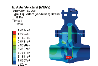
The deformation of the Scheme 1 gate valve is shown in Fig. 16 and Fig. 17. The gate valve deformed to the right under high-temperature and high-pressure fluid loads because the ends of the pipe were fixed. This can also be attributed to the thermal expansion caused by the high temperature. The maximum deformation of the gate valve was about 1.82 mm and located at the top of the stem. The maximum deformation of the gate was 0.78mm and located at the lower end of the gate.
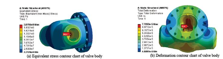
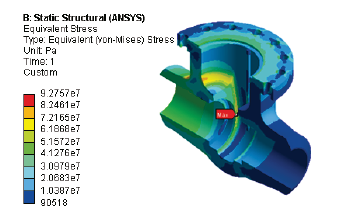
The equivalent stress distributions of the Scheme 1 gate valve is shown in Fig. 18-20. Due to the pressure and temperature of the fluid, the stress was high at the inlet section, valve seat, and gate. The maximum equivalent stress was 143.14 MPa and located in the gate chamfer, where the stress concentration can be clearly observed. The maximum equivalent stress of the valve body was 92.76 MPa and located at the chamfering of the seat.
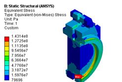
The maximum equivalent stress of Scheme 1 under the closed state of the gate valve was 143.14 MPa, the maximum equivalent stress of Scheme 2 was 143.6 MPa, and the maximum equivalent stress of Scheme 3 was 144.25 MPa. The maximum equivalent stress of Scheme 1 is the smallest, Scheme 2 is the second, and Scheme 3 is the largest. The maximum equivalent stress of the three schemes did not markedly differ and the positions were the same. The maximum deformation of the gate valve and maximum equivalent stress of the gate were also very small.
The analysis indicates that all three gate valve designs meet the given stress requirements and have very small stress and deformation distribution and size. Scheme 1 is preferable in regards to its smallest stress and mass properties by comparison to Schemes 2 and 3.
8. Conclusions
The results of this study can be summarized as follows.
(1) The strength and stiffness of the initial nuclear valve can be calculated by finite element analysis and to determine the size and distribution of the deformation and equivalent stress under test pressure and working pressure conditions. Under 37.5 MPa test pressure, the stress concentration is located in the chamfer of the valve seat and the maximum equivalent stress of the valve body is 219.2 MPa, which exceeds the permissible stress of the material and indicates that the strength does not meet the design requirements. Under 25 MPa working pressure, the valve body meets stiffness and strength requirements but the stress concentration at the chamfering of the seat part persists. It is necessary improve the stress concentration position in the valve body to enhance the safety and economy of the device.
(2) The structure of the valve body was optimized by testing three optimization schemes per their effects on the stress and deformation of the valve body. The maximum equivalent stress of Scheme 1 is the largest and its maximum deformation and mass are smallest among the three schemes. The maximum deformation of Scheme 2 is the largest. The maximum equivalent stress of Scheme 3 is the smallest and its mass is the highest. The optimization scheme improves the stress distribution of the valve body and decreases the stress at the original stress concentration point while making the stress distribution more uniform. This provides a theoretical basis for improving the entire valve body structure.
(3) Numerical calculations and fluid-solid thermal coupling analysis of the main over-flow and pressure-bearing parts in the closed gate valve were conducted to optimize the structure of the valve. The gate valve structure (with all three schemes) meets the given stress and deformation requirements under the working conditions. The difference between the sizes is very small across the three schemes; the stress and mass of Scheme 1 are the smallest.

