


 Inglês (pdf)
 Artigo em XML
 Referências do artigo
 Enviar este artigo por email
 Citado por SciELO
  Citado por Google
  Similares em
SciELO
Similares em
SciELO  Similares em Google
 Permalink
1. Introduction
The components of machinery used for processing cement or sugar cane, mining, earth moving, and rock and minerals handling can fail because of abrasive wear. Typically, the materials used for those applications have been superficially modified to control wear, but the cost of abrasion could reach 4% of the gross national product in industrialized countries [1].
Currently, numerous techniques for the deposition of hardened layers are available. Plasma spraying, laser cladding, hardfacing, thermal spraying, and chemical and physical vapor deposition are widely used to modify the surfaces. However, welding processes such as GMAW, SMAW, GTAW, and FCAW have emerged as solutions to improve wear resistance in metal-to-earth abrasive applications [2]. Among such metal manual arc processes, SMAW offers several advantages related to equipment cost and the availability of filler materials, while GMAW and FCAW have a high deposition rate [3]. In turn, GTAW is very clean and produces no slag [4]. However, SMAW is preferred in the field since the equipment is portable and inexpensive. In addition, by using SMAW, carbides, which offer a high hardness, can be deposited and the matrix can be also tough [5].
Tungsten-based carbides have been traditionally used for hardfacing applications. Nevertheless, high-chromium alloys are also suitable for metal-to-earth applications since the hardness of M7C3 carbides can reach up to 1600 HV [6]. New alloys modified with other elements to promote carbide formation have been used to improve hardfacing properties. Some authors have studied FeCrC and FeCB [5] hardfacing alloys, new materials modified with tungsten carbides [7], and, recently, alloys with high Mo contents [8] and silicide-strengthened hardfacing steels [9].
Another way to improve wear resistance in alloys is to add niobium, molybdenum, and titanium to the Fe-C-B systems. Those elements are used to precipitate the hard phases [10]. Carbides are typically the hard phases; they appear in a blocky shape and in a volume content of approximately 5%, with hardness values between 1200 and 1900HV0.1kg [11].
In recent years, nanostructured materials (NMs) and several consumables that deposit hard nanostructured coatings have been studied, focusing on their microstructural evolution and wear resistance. Tubular FCAW filler metals have exhibited outstanding properties due to their characteristics in the nanoscale compared to those of conventional grain materials [12]. Specifically, these materials show an extremely high hardness that could be explained by their small crystallite size, which ranges between 30 and 50 nm. They can also form ultrahard niobium precipitates and boron rich or with tungsten carbides which increase wear resistance [13].
In order to improve the wear resistance of hardfacing alloys, nanostructured rare earth oxides (REOs) have also been studied [11]. Wang et al. [11] analyzed the microstructure of nanostructured additives with rare earth oxides added to a high chromium cast iron (HCCI). They also characterized the primary carbide fraction volume and concluded that the use of nanostructured REOs increases the primary carbide fraction. Their study also included a pin-on-disk sliding wear experiment. Pin-on-disk tests have been used to explore the effect of nano-additives on wear rates [12]. Other authors have also investigated the effect of nano-additives on the wear rates measured by pin-on-disc tests [14]. In their case, when nano-additives were added to the alloy, the eutectic matrix seemed to support brittle carbides and avoid cracking in the coating. They also found that the KIC of the coatings was improved by the presence of the additives, and, consequently, their wear resistance can also be improved by reducing microcracking.
In summary, hardfacing coatings deposited by SMAW can be used to quickly repair worn components in the mining industry. To the best of our knowledge, the literature includes a limited number of studies into the wear resistance of alloys containing Nb nanocarbides [15,13,16]; however, the available articles do not analyze nanocarbides in a coating made using a single layer. Therefore, the aim of this study is to evaluate the wear resistance of a single-layer nanostructured hardfacing coating deposited by SMAW. The outstanding hardness of the coating (around 71 HRc for a single layer) is considered one of its main characteristics. The coating is characterized as nanostructured by the manufacturer, and this study evaluates its properties (such as hardness, microstructure, and wear resistance) by two different laboratory tests. The main contribution of this article is the complete characterization of the microstructure of nanostructured coatings (including nanocarbides) and the evaluation of wear resistance of a single-layer coating.
2. Materials and methods
2.1. Materials and welding procedures
The nanostructured hardfacing coating was manually deposited by the shielded metal arc welding (SMAW) process. The coatings were manually applied, and a direct current electrode positive (DCEP) with a Millar Dynasty 35 power source was employed. The diameter of the hardfacing filler metal was 3.96 mm. An ASTM A36 steel test coupon (150x150x12.5 mm) was used to deposit the weld beads according to the ASME’s IX Boiler and Vessel Pressure components code [17]. The chemical composition of the substrate provided by the manufacturer is detailed in Table 1.
Table 1 Nominal chemical composition of ASTM A36 steel.
| IX (2015) | |||||
| %C | %Si | %S | %Cu | %P | %Fe |
| 0.25 | 0.40 | 0.05 | 0.20 | 0.04 | Balance |
Source: The Authors.
Four ASTM A36 carbon plates (100x100x100 mm) were used to produce the weld beads and measure the dilution percentage. According to Dupont et al. [18], dilution is important for hardfacing coatings since it can significantly modify the coatings’ chemical composition and, consequently, their microstructure. The test coupons were carefully cleaned using acetone and a power wire brush before welding. The electrodes were placed in an electric oven for two hours at 120 ºC. Two single weld beads were deposited on each test coupon using 135A and 150A (amperage values recommended by the manufacturer) at a constant travel speed of 7 in/min. No preheat/postweld heat treatment was applied. The total number of specimens for the dilution test was 8 (2 specimens per plate).
After welding, an abrasive cut wheel was used to remove two specimens from each test coupon. Every cross section was prepared by conventional grinding and using abrasive papers of 60, 120, 280, 400, 600, and 1000 grits to polish the specimens. The polished specimens were etched in a 2 wt pct Nital solution (see Fig. 1b). The samples were inspected in an optical microscope, and the free software ImageJ was used to measure the size and amount of carbides. The dilution was calculated by the equation proposed by Dupont et al. [18].
Source: The Authors.
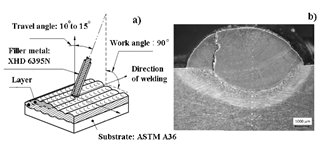
Figure 1. a) Scheme of the welding technique. b) Cross section used to measure dilution.
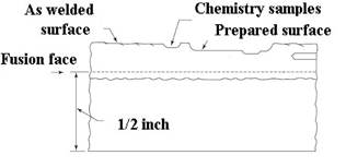
Fig. 2 shows a longitudinal section of the final test coupon used to extract samples for the abrasion test and welded using a welding procedure specification (WPS) according to ASME’s Boiler and Pressure Vessel Code [17], as summarized in Table 2. The WPS suggested the application of one hardfacing layer in the flat position (bead on plate) using the SMAW process without any preheat/postweld heat treatment. Additionally, applying the backhand welding technique, stringer overlapped beads were deposited without any transverse oscillation of the electrode (Fig. 1a). The single-layer deposit was placed along the full length of the plate using 135 amperes. The electrical welding parameters were kept constant, and the diameter of the electrodes was 3.97 mm (5/32”). The test coupon was left to cool down naturally to room temperature and a visual examination was performed to determine its acceptability according to the proposed WPS.
Table 2 Overview of Welding Procedure Specification (WPS). Essential variables in the special process (hard-facing overlay) according to ASME IX (2015).
| Parameter | Value | Parameter | Value |
|---|---|---|---|
| Process | Manual SMAW | Technique | Forehand |
| Joints (QW-402) | t= 6mm | Type of Bead | String |
| Base Metal (QW-403) | P.No=1, Group=1, UNS Number SA-36 | Electrical Characteristics (QW-409) | Number of layers: 1 Type of current and polarity; DCEP |
| Thickness | T< 12.7 mm | Current | 125-150 |
| Filler Metals (QW-404) | F-No=71, A-No= 6, Size= 3.97 mm (5/32 pulg), Rod, | Voltage | 28-37 |
| Hardness | 67-70 HRC | Travel Speed | 2.5-3.5 mm/seg |
| Position (QW-405) | Flat, bead-on-plate | Note | Cracks are allowed in the weld deposit |
| Interpass Temperature | T=120 °C | Chemical Composition | As reported in Table 1 |
Source: The Authors.
Liquid penetrant testing was used considering the minimum requirements in Table T-621 as the reference values [19].Type II (Visible Penetrant Examination) and Method C (Solvent Removable) were chosen based on Table 1 (Classification of Penetrant Examination Types and Method) and in agreement with SE-165 of Article 24. A universal grinder machine and a grinding wheel were used to grind both the hardfacing and the top surface (205x19x31.75 mm in size) at a maximum angular speed of 3600RPM (40m/s). The liquid penetrant method was employed to evaluate the material under the acceptance standards detailed in the procedure specification.
2.2. Hardness measurements
The hardness of the specimens was measured by the Vickers hardness test applying of a force of 2 kgf for 9s. The hardness of the hard phases was measured by the microhardness test, with a Vickers indenter, applying a force of 0.05 Kgf for 12s. The base metal, heat affected zone and the weld cross-sections central axes of the weld cross sections were indented every 500 µm.
2.3. Microstructure and chemical analysis
A set of 20x20-mm samples was used for microstructural characterization. They were metallographically polished and etched in a solution of Nital 2 % wt. A Nikon Eclipse Ci-L/S Light Optical Microscope (LOM) was used to analyze the microstructure and the carbides. The chemical composition was studied by Field-Emission Scanning Electron Microscopy (FE-SEM) in a JEOL JSM7100F and a backscattered electron detector (BED) in compositional mode. Furthermore, Energy Dispersive spectroscopy (EDS) was used for the elemental concentration. Image analysis was employed to determine the volume fraction of carbides.
X-ray diffraction characterization was performed to determine the carbides present in the hardfacing overlay. A Panalytical X’Pert Pro diffractometer with Cu-Kα radiation was employed with a step size of 0.002º from 15 to 140 2 tetha degrees and a time step of 9s. Optical emission spectrometry (OES) and X-ray fluorescence spectrometry analysis were used for the chemical analysis.
2.4. Abrasive wear tests
ASTM G99 and ASTM G65 wear tests have been extensively used to measure wear resistance of hardfacing coatings. Previous studies [13] have reported a correlation between the number of layers and wear resistance measured according to ASTM G65-04. Other researchers have also used ASTM G99 to measure the wear resistance of hardfacing coatings, as demonstrated by Gualco et al. [16]. In their paper, two wear tests (ASTM G65 and ASTM G99) were performed.
In this study, the ASTM G99 test method was used for wear testing with a pin-on-disk apparatus. Water jet cutting was used for the extraction of the pins from the prepared test coupon once the top surface of the hardfacing was grinded using a universal grinder machine. Acetone was used to clean the surfaces of all the samples. All the samples were weighed in an electronic balance (Sartorius, +/- 0.01 mg). Flat-ended pins were employed during the tests. An abrasive cloth composed of alumina was used with abrasives 0.4 mm in size; their morphology is detailed in Fig. 3b.
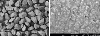
The statistical software Minitab (free version) was used to analyze the variables (load and sliding speed), effects, and interactions in the tribotest using a factorial design. As the abrasive tests were not conducted on the same day, two blocks of experiments were proposed. Two levels of force, high and low, were defined at 20 N and 40 N, respectively, and the two levels of velocity were 0.4 m/s and 0.6 m/s. The predetermined level of significance was α = 0.05 [20]. The ASTM G65 test (dry sand/rubber wheel abrasion test) was also performed to evaluate the wear behavior of the hardfacing coating. The wear tests were conducted using AFS 50/70 sand, whose morphology is shown in Fig. 3a. The test specimens were cut in rectangular shapes of 25x76 mm and between 3.2 and 12.7 mm thick. The sand was placed into a hopper and introduced between the specimen and the rotating wheel. Next, the specimen was pressed with 130 N by means of a lever while a constant rate of sand flow between 300 and 400 g/min was fed. As per ASTM G65, the duration of this abrasion test was 30 min. Before testing, acetone was used for cleaning the specimens, which were then weighted. Three tests were conducted at a room temperature of 24-27°C. Each test was run up to a sliding distance of (4309 m).
Generally speaking, both wear tests evaluate the abrasive resistance of coatings to abrasion. ASTM G65 can be considered as a three-body abrasion tests and ASTM G99 can be considered as a two-body abrasion test. Performing both tests will provide a complete outline of coating’s resistance to abrasion
3. Results and discussion
3.1. Dilution measurements
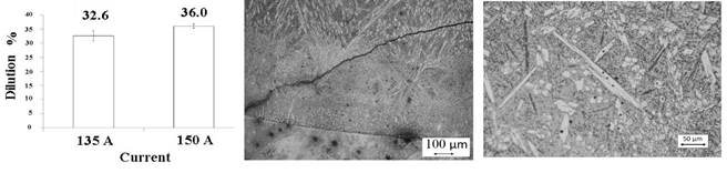
Based on the results of the dilution measurements, the two amperage levels did not show a significant difference; however, the dilution obtained was consistent for shielding metal arc welding (20-45%) [21] (see Fig. 4). Welding current is not considered an essential variable and, consequently, any of the two amperages was appropriate to be used. However, to evaluate the proposed welding procedure and considering the dilution, 135 A was chosen as the most convenient amperage for the test. Since no significant variations in dilution were found with the two amperages, the microstructure of hardfacing alloy was expected to remain unmodified. The flat position (Bead On Plate, BOP) was used during the welding test by employing stringer beads and a backhand welding technique. Another important feature observed during the analysis of the cross section of the single pass welding is that there were cracks in the beads, as shown in Fig. 4b. Those cracks will be discussed in the next section. Fig. 4c shows some of the carbides in the microstructure, which will be discussed in detail in Section 3.3.
3.2. Visual inspection
The welding test coupon exhibited a good appearance and no spatter or undercut on the surface was identified (not shown). Transverse cracks were observed; they appeared once the first weld bead was deposited and then propagated to the neighboring bead.
Because these cracks were formed at high temperatures during the welding process, they are considered hot cracks. Such cracks were also characterized as weld solidification cracks, and they were formed by the natural shrinkage during the solidification process when the microstructure is susceptible [22] (see Fig. 4a). As suggested by the welding procedure specification, a liquid penetrant testing was performed, and the cracks were visible.
The cracks appeared because of differences in the thermal expansion between the deposited and the base metal. These differences generate strains in the hardfacing deposit created during the cooling. In addition, the chemical study of the hardfacing electrode revealed that it can be considered a high-alloy electrode; in the literature about applications without preheat treatments, these materials are susceptible to cracking and cross-checking [23]. Nevertheless, this discontinuity is not detrimental to hardfacing applications; in fact, cross checking can favor hardfacing applications by relieving stresses [1]. Cracks are allowed and they are not a major concern for the proposed WPS.
Table 3 shows the chemical analysis of the hardfacing deposit. When the results of the chemical composition (Cr and C contents) were plotted in a Jackson diagram [24] (not shown), the alloy was found to be hypereutectic, composed of primary carbides and a eutectic matrix, which is expected for this hardfacing alloy in the first layer. The high carbon and boron contents and the presence of carbide former Nb produce primary carbides even in the diluted first layer of the hardfacing deposit [25]. As the alloy is also rich in Cr and C, M7C3 carbides are created during the solidification due to segregation. M7C3 were chromium-rich while NbC are boron rich since they can be described as complex carbides where the B substitutes C in the lattice.
Table 3 Chemical composition of hardfacing (one layer) and hardness values.
| %C | %Nb | %Cr | %B | %Fe | %Mn | %Si | Hardness | |
|---|---|---|---|---|---|---|---|---|
| One layer (Measured by XRF) | 3.8 | 3.4 | 13.2 | 1.3 | 81.2 | 0.3 | 0.42 | 1092±23.6 |
| Phase 1 - Chromium carbide (Measured by EDS) | 17.7 | - | 62.8 | - | 19.4 | - | - | 1592±73.8 |
| Phase 2 - Niobium carbide (Measured by EDS) | 21.7 | 71.2 | 2.4 | - | 4.5 | - | - | Not measured |
| Phase 3 - Boron carbide (Measured by EDS) | 22.7 | 54.2 | 2.3 | 17.4 | 3.2 | - | - | Not measured |
Note 1: All elements in weight %
Source: The Authors.
3.3. Microstructure and hardness
Fig. 5a shows the typical microstructure found on the hardfacing deposit surface. It has been reported that dilution is maximum next to the fusion line and, consequently, the microstructure is formed by austenite dendrites and secondary eutectic M7C3 carbides [26]. Fig. 5a shows the primary M7C3 (arrow 1), and arrow 2 in the same figure marks a zone with the eutectic microstructure. The microstructure of the ASTM A36 steel (not shown) is composed of ferrite and the hardness of the substrate is 160 ± 10 HV.
SEM/EDS analyses and their microhardness results confirm the nature of the carbides found in the hardfacing. Fig. 5b (arrow 1) shows elongated M7C3-type chromium carbides. These results are different from those obtained by J. Gou et al. [27], who found that carbides were arbitrarily oriented when the hardfacing was subjected to natural cooling conditions. Arrow 2 shows the carbides found in secondary dendritic arms. Arrow 3 in the same figure shows Nb-rich carbides dispersed all over the transverse section, and arrow 4 marks deformed Nb- and B-rich carbides. The manufacturer of this hardfacing coating welding electrode claims that the electrode was produced using nanotechnology [13]. The deposit can be characterized as nanostructured, with ultrahard niobium precipitates added to improve abrasion resistance. The hardness of some chromium carbides (in the microscale) was around 1000 HV. FE-SEM and BED (compositional images) were used to obtain images in the nanoscale, as shown in Fig. 5c. Such image shows some nanostructured carbides with a mean size of approximately 91 nm, which implies that the alloy is effectively nanostructured according to the international standard ISO/TS 80004-1:2010 since the dimensions of the carbides are in the nanoscale. Said standard defines a nanostructured material as “a nanostructured material is that one having internal nanostructure or surface nanostructure”. Therefore, as confirmed in SEM images, the size of the carbides developed with the coating process was found to be in the nanoscale and, according to the ISO definition, the coating could be deemed nanostructured. The authors evaluated the microhardness using a profile, but it did not provide reliable information since the microhardness varies depending on the location of the indentation (matrix or carbides.
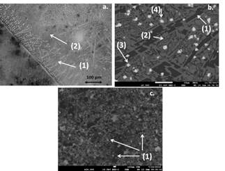
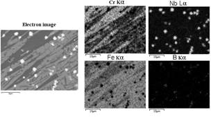
Fig. 6 presents an EDS map with the main phases. Fig. 6 clearly shows the Nb carbides and another important detail about those carbides: some of them are boron-rich (see the bottom right figure). Energy dispersive spectroscopy (EDS) was also used to identify the carbides produced during the solidification of the overlay weld pool. The localized spectra are shown in Table 3. Based on these results, the carbides present in the hardfacing microstructure are classified as M7C3 (Nb-rich) and (Cr-rich) carbides. Due to the presence of chromium, iron, carbon, and low amounts of alloying components (such as silicon, manganese, boron, molybdenum, niobium, and the M7C3 carbides) and based on previous reports [27], the hardfacing investigated in this study was classified as chromium carbide (CCOs).
The volume content of Nb-rich carbides was found to be 5.3% v/v, and their distribution was homogeneous. The Cr-rich carbides were observed at a volume content of 43.6% v/v. Self-shielded flux cored wires produced a similar result in terms of carbide volume fraction of primary carbides, which remained at around 43.2 % wt. Moreover, the authors found that the primary carbide volume fraction in the hardfacing deposit without nano REOs was 17.1%; in turn, the primary carbide volume fraction increases to 28.8 wt% when the nano REOs reach a maximum of 22.2% [28]. The resistance to abrasive wear is expected to increase when the volume of carbides is higher for alloys with traditional M7C3 carbides [29]. The effect is unknow for nanostructured carbides but a volume of 43.65% of carbides is considered beneficial for this application.
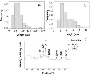
Fig. 7a presents the size distribution histograms of the Nb and Cr carbides, respectively. The Cr-rich carbides were found to be transversely oriented, with carbide clusters of 60 μm approximately. The distribution of the Cr-rich carbides longitudinally oriented is almost symmetric; their size ranges between 50μm and 100 μm, with some at 200 and 250 μm. Unlike, the histogram of Nb-rich carbides (see Fig. 7b) is nearly symmetric, with a mean size of carbides at around 2 μm. Those distributions did not take into account carbides with a mean size under 500 nm.
Source: The Authors.
Figure 7. a) Histogram of chromium carbide. b) Histogram of NbC. c) X-ray pattern.
An additional test of a two-layer hardfacing application was performed using the same parameters described above, except for the current (150 A instead of 130 A). In terms of microstructure, the SEM images (not shown) exhibited a similar orientation and distribution of carbides compared to the single-layer application. In the two-layer application, primary Nb carbides were found in a volume fraction of 4.8%, whereas the Cr-rich carbides were found in a volume content of 40.2%. The variation in terms of microstructure was not substantial, even though the highest welding current was used for the two-layer application. These results are in agreement with those obtained by M. Kirchgaßner, E. Badisch, and F. Frane [11], who found Nb-rich carbides at a volume of 7% with a size of ≤ 3 μm in different shapes and Cr-rich carbides at a volume of 57.1 % with sizes between 30 and 200 μm. Although the volume fraction of small Nb-rich carbides is 5.3%, they can be considered the most important factor to increase abrasion resistance in the hardfacing deposit.
The XRD pattern of the hardfacing coating is presented in Fig. 7c. Austenite, NbC, and M7C3 can be identified, which is in agreement with the results published by other authors [15,30,31]. The microstructure can be found in the diagrams proposed by Jackson [24]. The micrographs (Fig. 5) confirm a hypereutectic microstructure. In this case, the microstructure is formed by primary carbides (proeutectic) inserted in the austenitic matrix.
The hardness of the coating and the hard phases is detailed in Table 3. The hardness of the coating (1029HV200 g, 15 s) is very similar to that of other nanostructured hardfacing coatings reported in the literature [12,13]. In the table, the microhardness of the primary carbides is 1592HV50 g, 15 seg. This value is also very similar to that reported in other studies into M7C3 carbides (1587HV50 g, 15 seg) [27,32]. Since the Nb-rich carbides were very small, it was not possible to perform hardness measurements.
3.4. Abrasive wear
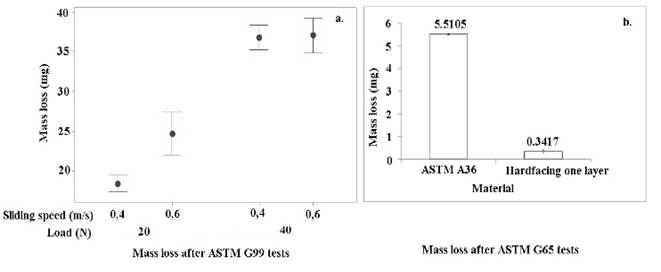
Fig. 8 presents the mass losses of the coating after two different tests: ASTM G99 and ASTM G65. Fig. 8a details the values obtained after pin-on-disc tests. The base metal lost 1700 mg after the wear tests with high loads and a sliding distance of 204 m. The coating lost 37 mg at the same load and after running the tests for 2716 m. The wear rates of both materials were calculated; values of 8.3 mg/m in the base metal were obtained, in contrast with 0.013 mg/m in the nanostructured hardfacing coating. These values confirm a reduction of 638 times in terms of mass loss in the hardfacing coating compared to the base metal in the pin-on-disc test. An analysis of variance allowed us to conclude that the load effect is statistically significant at a p-value of 0.05 with a 95.22% confidence level. In addition, the interaction effect and sliding speed appear to be not significant when p-values higher than 0.05 are used.
A different behavior was found with low loads, and mass losses increased when the sliding speed was higher. This result probably indicates that a transition from a wear mechanism was found for the velocities under study. One plausible explanation found in the literature is that mass losses are higher since friction heating is expected to increase along with sliding speed [33]. However, a comprehensive understanding of this result is beyond the scope of this article.
Fig. 8b presents the mass losses after the dry-sand rubber wheel procedure (ASTM G65). The mass loss of the hardfacing was found to be 14 times lower than those obtained in the base metal. The difference between the results in the pin-on-disk tests and the dry-sand rubber tests can be explained by the fact that, in the first one, the pin passes over the same track repeatedly. Hence, lower mass losses are expected in pin-on-disk tests since the abrasive particles are detached from the cloth.
Source: The Authors.
Figure 8. a) Mass losses after conducting ASTM G99 tests. b) Mass losses after conducting ASTM G65 tests.
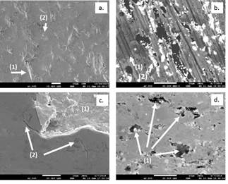
Fig. 9 shows the FE-SEM images of the worn samples, which present different wear mechanisms that can be identified. In Fig. 9a, arrows 1 and 2 show the microploughing on the surfaces due to abrasive wear; this is reflected in a deformed material on the side of the wear groove (see arrow 1 in Fig. 9a). Material removal by microcutting events can also be observed (arrow 2 in Fig. 9a). Fig. 9b is a back-scattering electron image where white regions represent the carbides, grey regions are associated with the matrix, and black regions mark the holes left by the spalled carbides. The wear track clearly appears as continuous parallel grooves indicated by arrow 1. The track can be observed as plastic deformation produced during abrasion. Moreover, the effect of carbides can also be seen in the same image. The carbides stop, to some extent, the continuity of the wear tracks that are generated (see arrow 2 in Fig. 9b) in the wear process. The same effect of Nb carbides was found in the overall wear performance previously reported by other authors [15].
Source: The Authors.
Figure 9 Wear mechanisms. a) Microcutting and microploughing on worn surfaces. b) Cracks and spalling of Nb carbides. Microcracks. d) Spalling near chromium carbides.
Microcracking was also identified in the matrix at a higher magnification (see Fig. 9c). A brittle fracture is marked in the image with the arrows (2); this wear mechanism has been extensively reported in this kind of materials [14]. Finally, Fig. 9d presents carbides removal by spalling as well. In the figure, the arrows point to the holes left by the carbides, evidenced also by small residues of carbides left behind on the edges of the holes.
4. Conclusions
A single layer of a nanostructured hardfacing alloy was studied in this paper. The results show that there is no variation in dilution using the welding parameters described above. The dilution was around 36%, and hardness values of 1029 HV 50 g, 15 seg were obtained in the weld metal overlay. The microstructure of the hardfacing coating was hypereutectic, and it was formed by an austenitic matrix with large (around 60 μm) proeutectic Cr-rich carbides (43.6%). There were also NbC (5.3%) in the microscale (around 2 μm) and other carbides (sizes under 91 nm) in the nanoscale.
Compared to the base metal (ASTM A36) used for the hardfacing, the wear resistance of the alloy was improved 14 times when tested in the dry-wheel rubber sand. When the hardfacing was tested in the pin-on-disc machine, the wear resistance did not change with different velocities if the load was high. When lower loads were used, the velocity had a significant effect on wear resistance. Microcracking, spalling of carbides, and microploughing were the predominant wear mechanisms identified in the SEM analysis of the pins worn surfaces.

