


 Inglés (pdf)
 Articulo en XML
 Referencias del artículo
 Enviar articulo por email
 Citado por SciELO
  Citado por Google
  Similares en
SciELO
Similares en
SciELO  Similares en Google
 Permalink
1. Introduction
The TBC are used in the hot sections of the blades of aeronautic and terrestrial turbines. These TBCs reduce heat transfer due to combustion gases, provide protection against hot corrosion and oxidation of critical components, thus increasing their service life [1]. Generally, a TBC consists of two layers of different material, which are deposited on a metal substrate. The outer layer is known as the top coat (TC), and the other is a metal alloy named layer of linkage (Bond Coat - BC). The TC is commonly made of yttria stabilized zirconia (YSZ) and the BC is usually made from a MCrAlY (M = Co, Ni, or Co+Ni) alloy, MCrAlY. TC is applied more in TBC coatings because of its thermal properties, such as low thermal conductivity, good thermal-shock resistance and relatively low thermal expansion coefficient [2]. The shape of this powder (TC) is spherical, although there are some slightly deformed ones. The spherical geometry ensures good flow through the powder feed system [3]. The BC promotes good adhesion of the TC to the substrate because it has a similar coefficient of thermal expansion as the substrate [4]. This layer provides protection against oxidation [2,5] and hot corrosion [5]. Thermal spray methods are normally used to make TBC due to fast and inexpensive procedure [6]. Some researchers [7-9] have shown that during deposition of thermal barrier coatings (TBC), residual stresses are generated. These stresses directly affect the mechanical properties of the coating. Furthermore, they reduce the service life and the component they cover. Thus, a deposition methodology to reduce the residual stresses is paramount.
Residual stresses are always present in thermal spray coatings. They are produced by two known mechanisms: i) the quenching of splats after impact on the substrate and the restricted contraction of the splats by adhesion to the substrate; and ii) the differential thermal expansion of the coating and the substrate during cooling.
According to Widjaja et al. [9], the end-stress state of a TBC is influenced not only by splats quenching and thermal mismatch but also by phase transformation during coating deposition.
Atmospheric Plasma Spraying (APS) projects molten particles at low speed. In this process, the gun has a copper cathode with a tungsten tip and a copper ring anode, both cooled by water flowing in an internal circuit. A high voltage electric arc is generated between the cathodes. When the gases pass through this high potential, the gases ionize, raising the temperature and producing the plasma. The ionization is obtained as a result of collisions between neutral gas molecules and the interaction with the electric arc. The plasma protrudes from the space between the electrodes in the form of a flame at the exit of the gun. The feed material in these systems is dust that is quantified and feed directly into the plasma flame. The dust on contact with plasma absorbs thermal and kinetic energy and is projected onto the substrate. The APS can reach a gas temperature of 12000 to 16000 ° C [10], so it is possible to melt ceramic materials.
In the HVOF process, the particles projected onto the substrate reach high speeds, and do so at lower temperatures than those measured in the APS process. This APS process generates a low velocity and high temperature plume, which is suitable for the deposition of ceramic powders. Despite these differences between HVOF and APS, the deposition of coatings to manufacture a TBC trough these processes is recommended. In both methods, the impact of the particles on the substrate generates residual compressive stresses [12], which reduce the tensile stresses that eventually cause the delamination of a coating in operation [13].
Improved TBC deposition technology can lead to gas turbines operating at high temperatures (about 1200° C), higher efficiency and better fuel performance of consumption [14], which reduces the generation of greenhouse gases [15]. However, due to the high temperatures at which the turbines operate, the TBCs are exposed to thermal and mechanical loads. In addition to a corrosive and oxidizing atmosphere, which can cause detachment of the ceramic layer [16]. In addition, the TBC are susceptible to degradation due to the molten oxides of calcium, magnesium, aluminum and silicate (CMAS). This CMAS resulting from the ingestion of siliceous mineral residues (dust, sand, ashes) that reach the turbine from the combustion chamber [17]. The mechanism produces catastrophic TBCs failure in engine components that are exposed to corrosive gases and extreme temperatures [18]. During the last decade, different techniques have been proposed to study the ultimate stress state of TBCs, for example bending [19], finite element simulation [20] and material removal [21], however, there are no studies that show the effect of the relationship between the amount of CMAS infiltrated and the magnitude of the residual stress profile. This relationship is paramount because help us to determine the critical stated of the TBC before delamination, detachment or even a total destruction of the TBC. In this study, the residual stress profile of the ceramic layer (TC) of a thermal barrier coating due to CMAS infiltration was determined using the Modified Layer Removal Method [22] and the method of Noda et al [23]. We show the effect of the relationship between the amount of CMAS infiltrated and the magnitude of the residual stress profile. This effect was measured on the TBC after it had been subjected to a temperature of 1250 ° C for 2 and 4 hours, respectively. We determine an increase of 26.446 MPa for 2 hours of thermal treatment and 30.743 MPa for 4 hours. In addition, it was observed that the formation of TGO (usually formed by Al2O3) is related to the increase in the magnitude of the residual stresses in the YSZ.
2. Experimental Procedure
2.1. TBC deposition
TBCs were deposited on AISI 304 stainless steel substrates of size 25.4 mm X 25.4 mm X 6.35 mm. The BC and TC were obtained by deposition of powders of a CoNiCrAlY (AMDRY 9954, Co32Ni21Cr8Al0.5Y), and yttria stabilized zirconia (NS-204, YSZ) alloy, respectively: both from Sulzer Metco. Then, the substrates were then cleaned with acetone and grit blasted by an air stream carrying alumina particles that impacted at a 45° angle at a distance of 200 mm, they were then re-cleaned with acetone; the surface roughness (Ra) ranged from 3 to 7 µm.
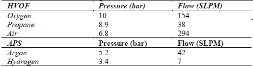
The BC was deposited by a HVOF system, model DJH2700 by Sulzer, with a powder feed rate of 38 g/min and a distance of 203 mm. The mean thickness of this layer was 300±7 µm. On the other hand, the TC was deposited by an APS system, model 9MB by Sulzer, with a powder feed rate of 45 g/min and a distance of 90 mm. The voltage and current of the gun were set at 67 V and 600 A, respectively [23]. The mean thickness of this layer was 180±5 µm. Each layer was formed by applying 16 times at a gun lateral displacement speed of 1.5 m/s. Table 1 shows the pressures (bar) and flow rates (SLPM, Standard Liters per Minute) of the gases used.
2.2. Thermal treatment of the coatings with CMAS attack in TBC´s
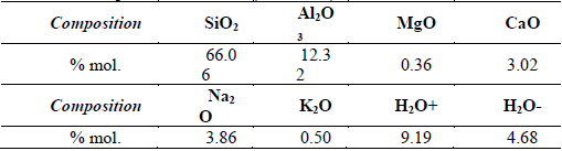
After depositing the TBC on the AISI 304 stainless steel substrate, the thermal treatment of the TBCs was carry out in a SWGL-1600x tubular furnace, at a temperature of 1250 ° C. These TBCs were grouped in pairs for testing with a replica, samples 6H-CC1 and 6H-CC2. During the heat treatment, they were subjected to a CMAS attack, which was placed on the coated surface, with a concentration of approximately 10 mg/cm2. The heating rate was 10 C°/min to a temperature of 1250°C, the cooling ramp 6 C°/ min with a vacuum of 10-5 mm Hg. The chemical composition of the Mordenite is shown in Table 2.
2.3. Residual stress determination
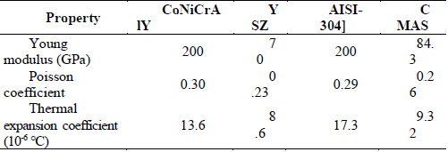
To calculate the residual stresses on the coatings, the physical properties of the materials were used (AISI 304), BC (CoNiCrAlY) y TC (YSZ), shown in Table 3.
The profile of the residual stress in the TBCs was determined by the technique MRCMRB [22] and Noda Equations [23].
According to the method modified by Yanez et al [22], the mathematical analysis of the stress was performed using the following equation:

Where kxz and kyz are sample curvatures. For a plain stress state, the stress-deformation equation is given by:
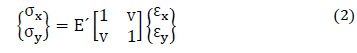
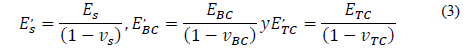
Where E' is a relationship that involves the Young modulus and v the Poisson ratio of the materials E' s, is the Young modulus of the substrate, E' BC , of the BC, and E' TC , of the TC:
Where E' t , is the overall Young modulus of the TBC:
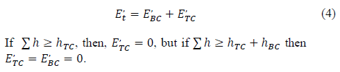
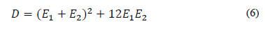
The Noda equations [23] were taken as the basis for determining residual stresses due to the difference between thermal expansion coefficients between TC, BC and substrate (Thermal Stress), as shown below.
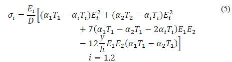
Where.
Equation (5) is reduced to.
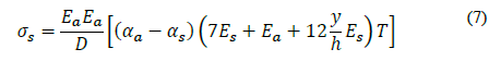
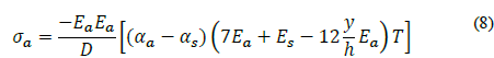
Where σ s is the residual stress of the BC; E s and α s are the Young's modulus and the coefficient of thermal expansion of the BC, respectively. σ c is the residual stress of the TC; E c y α c are the Young's modulus and the coefficient of thermal expansion of the TC respectively. The thickness of the coating h is the total thickness; and T is the deposition temperature of the coating.
3. Results and Discussion
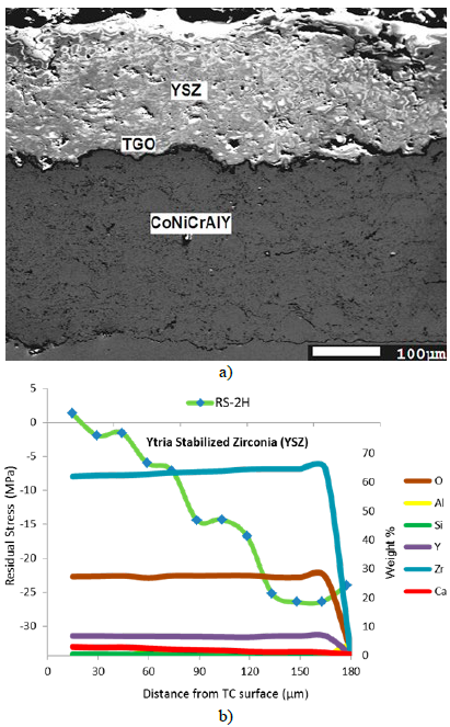
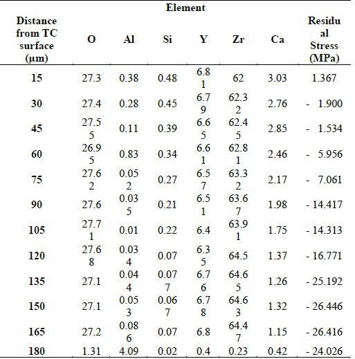
Fig. 1 shows the micrograph and a comparison profile between the residual stress and the infiltrated amount of CMAS in the YSZ (TC) of the TBC. This procedure was subjected to heat treatment (1250°C), and CMAS attack (10 mg/cm2) for 2 hours (RS-2H). In Table 4 shows the quantification in weight percent of the TC elements. The measurement was performed by EDS in the scanning electron microscope (SEM). It can be seen that the magnitude of the compression residual stress about 30 μm of the surface of the TC is 1.9 MPa and the weight percentage of Si and Ca are 0.45 and 2.76, respectively. Approximately 60-μm of depth from the surface of the TC, the values of the weight percentage of the Si and Ca decrease to 0.34 and 2.46 respectively, and the compressive residual stress was increased to 5,956 MPa. At 90 μm, the values of the weight percentage of Si and Ca are 0.21 and 1.98 respectively, and the compressive residual stress increases to 14,417 MPa. At 120 μm, the values of the weight percentage of Si and Ca are 0.07 and 1.37, respectively and the residual compressive stress increases to 16,771 MPa. At an approximate depth of 165μm, near of the BC, the amount of Si and Ca decreases 0.07 and 1.15 respectively, at this depth the compressive residual stress is increased to a value of 26,416 MPa. To enter the interface with the BC the stress undergoes a slight increase to compression of 24,026 MPa, and the weight percentage of Ca and Si decreased to 0.02 and 0.43, respectively (Fig. 1 and Table 2). With these results, we can mention the following argument: more depth of the CMAS infiltrated in the TC, more amount of the CMAS, and more magnitude of compressive residual stresses. In addition, exists a decrement of the weight percentage of the Y and increment of the weight percentage of the Zr. This is because YSZ might tends to dissolve and precipitate with a different composition (lower Y) due to the CMAS attack.
Source: The Authors.
Figure 1 a) Relationship between residual stresses and the weight percent amount, and b) the micrograph of the RS-2H sample.
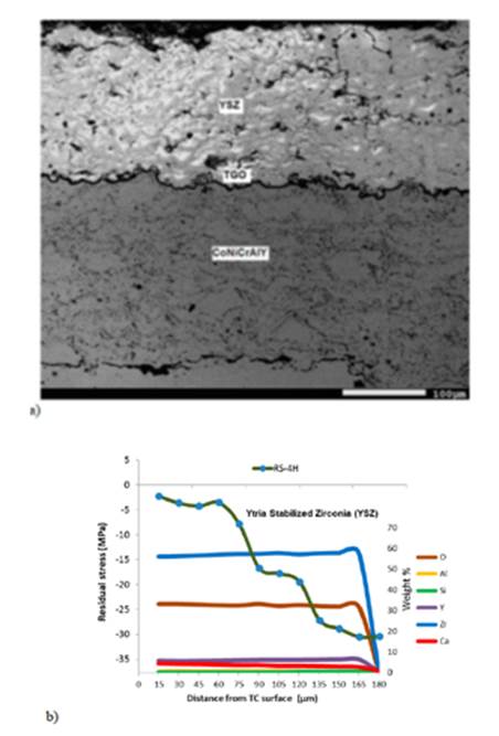
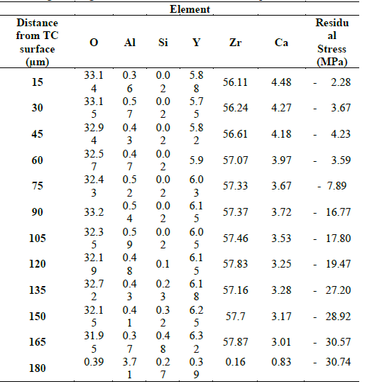
Fig. 2 shows the micrograph and the relationship between the residual stress profile and the infiltrated amount of CMAS in the YSZ (TC) of the coated samples. This experimental procedure was as following: the samples were subjected to thermal treatment (1250 ° C) with CMAS attack (10 mg / cm2) for 4 hours (RS-4H). This evaluation suggests a higher residual stress when the TBC is exposed during a longer time. Table 5 shows the quantification in weight percent of the TC elements. The quantification was performed by EDS in the scanning electron microscope (SEM). It can be seen that the magnitude of the compression residual stress about 30 μm from the surface of the TC is 3.675 MPa and the weight percentage of Si and Ca are 0.02 y 4.27, respectively (Fig. 2 and Table 5). At approximately 60 μm from the surface of the TC the values of the weight percentage of the Si and Ca are 0.02 y 3.97, respectively, the residual stress at this depth decreases slightly to 3,595 MPa. Around 90 μm the values of the weight percentage of the Si and Ca are of 0.02 and 3.72, respectively, and the compression residual stress increases to 16.775 MPa. At the depth of 120 μm, the values of the weight percentage of the Si and Ca are of 0.1 and 3.25, respectively, in this depth compression residual stress increases to 19.479 MPa. At a depth of 180μm, near of the BC, the amount of Si increases to 0.48, the Ca percentage decreases to 2.78, and the compression residual stress increases to 30.456 MPa. At an approximate depth of 190 μm, within the BC, a residual tensile stress of 30.743 MPa was measured, and the weight percentage of Ca and Si decrease to 0.27 and 0.83, respectively. With these results, we can mention the following argument: In the same way as in Fig. 1 y Table 2 (RS-2H sample), one can observe increment in the magnitude of the compressive residual stresses, when increases the depth infiltration of CMAS as mention in first evaluation. In addition, a clear difference with the previous procedure, we note that the infiltration of Si, Ca and compression residual stresses were increased.
Source: The Authors.
Figure 2 a) Relationship between residual stresses and the weight percent amount, and b) the micrograph of RS-4H sample.
The samples were subjected to thermal treatment (1250 ° C) with CMAS attack (10 mg / cm2) for 2 hours (RS-2H) and 4 hours (RS-4H), respectively. In both cases (RS-2 H and RS-4 H), it can be observed that the residual stress profile increases gradually, due to increase of the depth of CMAS infiltrated in the TC. In addition, a higher residual stress profile is observed in the sample (RS-4H), which was subjected to a longer thermal treatment. This may be related to the amount of Si and Ca infiltrated. In the RS-2H sample, we can observe that near of the TC the weight percentage of the infiltrated amount of Ca to a depth of 15 μm is greater than the infiltrated amount of Ca in the sample RS-4H. This similar trend is present along the depth of the TC, which indicate that the amount of Ca influences the magnitude of the residual stress profile. Another element that could also influence the magnitude of the residual stress profile is Si. We can be observed that near the TC surface of the sample RS-2H the Si has its greatest amount infiltrated in percentage of weight, is of 0.48. As it approaches the BC interface, the infiltrated quantity decreases to a minimum of 0.02. In the case of the sample RS-4H, close to the TC surface (15 μm) the infiltrated amount of Si is the smallest (0.02). From this smallest depth, a gradual increase of the infiltrated quantity of Si up to a depth of 165 μm, observing a value of 0.48 of weight percentage of the quantity infiltrated, which may indicate that when the infiltrated amount of Si is greater near the BC, the magnitude of the residual stress profile is increased. It can also be observed that the increase in compressive residual stress is related to increased stiffness of the TC (YSZ), which agrees with Wu et al [24]. They say that the infiltration of Si and Ca led to an accelerated sintering of YSZ coating. Sintering usually leads to shrinkage at the surface of a TBC. The sintering effect decreases gradually from the surface to the bond coat. This leads to an increase in Young’s Modulus, which decreases strain tolerance capability of the coating, and increases topcoat stresses [24].
Not only the infiltration of Si and Ca can be considered in increasing the magnitude of the residual stresses, but also the formation of TGO (Generally formed by Al2O3) in the interface of the TC and BC. Table 4 and 5 shows that the amount of Al increased to 180 μm of the TC surface, for the sample RS-2H is 4.09 and for the sample RS-4H is 3.71. Such behavior has also previously been reported by other authors [25, 26], who comment in their work, that the growth of the TGO provides compression residual stress, because its growth is impeded by the substrate. Other authors such as Busso et al [27] comment, that when the thermally grown oxide increases, residual stress increases. Ahrens et al [28], in their research work analyzed the TC (YSZ) deposited by APS, They could observe, that during cooling after a heat treatment, the TC and BC developed a greater contraction than the thermally grown oxide (TGO). This results in a state of compression residual stress in the TC and BC, because the coefficient of thermal expansion of the TGO is smaller than the coefficients of thermal expansion of the TC and BC.
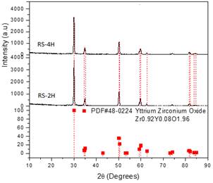
In Fig. 3 shows diffraction patterns of the samples RS-2H and RS-4H, the patterns were obtained with X-ray Diffractometer (XRD), The Rigaku DMax 2100 equipment was used, with a sweep range from 10 to 90 ° in 2ϴ, with a step of 0.02 °, incidence angle of 1 °, with a Cu tube at 30 kV and 20 mA. It can be seen that the diffraction patterns of the RS-2H and RS-4H samples are similar to the pattern of the YSZ layer (PDF # 48-0224 Yttrium Zirconium Oxide), therefore it can be said that there is no phase change. Due to the low concentration of CMAS (10 mg / cm2) used on the YSZ surface, the effect of sintering caused by infiltrated Ca and Si could be reduced. Therefore, a tetragonal to a monoclinic phase change was avoided, eliminating the possibility of formation of horizontal cracks of the TBC. Control degradation of the ceramic layer, allowed to determine the magnitude of the residual stresses due to the attack by CMAS.
4. Conclusions
The residual stress state at the TC (YSZ) that was deposited by thermal spraying was obtained by the modified layer removal method for duplex coatings (MLRMDC). This method resulted in residual stress profiles similar to those obtained by MLRM. This is a procedure regularly reported in the literature for determining residual stresses of thermally sprayed coatings. Residual stresses are beneficial to the durability of the coating to some extent. We perform a deposition of the TBC on the stainless steel substrates, which were heat-treated at 1250 °C, with a CMAS attack at a concentration of 10 mg/cm². The attack exposure was for 2 hours (RS-2H) and 4 hours (RS-4H), respectively. It was observed that, in both samples, the infiltration of Si and Ca into the YSZ increased the magnitude of the residual stress profile of compression. This, up to a certain magnitude, is beneficial for the durability of the lining. Furthermore, it was observed that in the sample with the longest exposure time to high temperature (4 hours at 1250 ° C) the amount infiltrated by CMAS was greater and that the magnitude of the residual stress profile was greater than the sample exposed to the shortest heat treatment time (2 hours at 1250 ° C). In addition, it was observed that the TGO formation is related to the increase in the magnitude of the residual stress profile of compression at the YSZ.

