


 Inglés (pdf)
 Articulo en XML
 Referencias del artículo
 Enviar articulo por email
 Citado por SciELO
  Citado por Google
  Similares en
SciELO
Similares en
SciELO  Similares en Google
 Permalink
1. Introduction
Chromium-molybdenum steels such as AISI-SAE 4130, 4140 and 4150 are heat-treatable low-alloy steels (HTLA) whose microstructure and mechanical properties are produced by quenching and tempering (Q&T) [1,2]. These alloys are mainly used in heavy machinery (shafts, gears, dies) [3], the automotive and aerospace industry [4-6] and large construction projects. The petroleum industry uses Cr-Mo 4130 and 4140 steels instead of carbon and low-alloy steels for drilling facilities (e.g., sludge and cement systems from oil and gas offshore rigs), and wellhead equipment (e.g., Christmas trees, heads, flanges and piping accessories) [7]. These kinds of steels with medium carbon plus additions of Cr-Mo can develop levels of tensile strength in excess of 774 MPa after the heat treatment proper to withstand the high pressure associated with drilling operations (10-15 ksi/69-100 MPa) with lower thicknesses than carbon steels [8].
AISI-SAE 4130 and 4140 steels have been welded with low-carbon filler metals which are usually high-strength low-alloys such as ER70S-D2[9], E8018-D2 [8], E10018-D2 and E10018-M [8], E8018-B2 [10], E9018-B3 H4 [7,11], ER80S-D2 [4,12], and even carbon steels such as ER70S-2 [12]. These filler metals do not match the mechanical properties of 4130 and 4140 steels and usually produce welded connections with a condition called “undermatching”, and reduce the susceptibility to hydrogen induced cracking or HIC [13]. In order to give the possibility to achieve matching properties after Q&T, some manufacturers (e.g., Lincoln, Midalloy, Harris) produce alloy filler metals like ER4130 for GMAW/GTAW which gives undiluted weld metals with the same chemical composition of AISI-SAE 4130 steel. This filler metal may be produced according to military standards as Type I from MIL-R-5632 [14] or other SAE aerospace standards such as SAE-AMS 6457 [15] and, for ER4140, SAE-AMS 6452 [16]. These fillers can be used to obtain matching strength welds in 4130 and 4140 base metals, respectively.
Among the available welding processes to weld 4130 and 4140 steels, gas metal arc welding (GMAW) is widely used in the industry because of its technical and economic advantages over other joining processes such as SMAW or GTAW. One of the main characteristics of GMAW is that its welding parameters change the way in which the molten metal is transferred from the electrode tip to the weld pool adopting different metal transfer modes (MTMs) such as: short-circuiting, globular (low-frequency metal droplets larger than the electrode diameter), spray (high frequency metal droplets smaller than the electrode diameter), and combinations of these basic MTMs. The MTM in GMAW depends on the class and diameter of the filler metal, voltage, amperage, shielding gas, electrode extension (and therefore contact tip to work distance, CTWD) and polarity [17]. Welds made with a given MTM have particular conditions of bead penetration, heat input, deposition rate, arc stability, surface condition, and spatter; thereby, a weld made with some MTM has specific performance characteristics, properties and applications. As a result, MTM is considered an essential variable in many welding codes (AWS, ASME, API) because it might impact the quality and performance of weldments, particularly, their mechanical properties.
Most welding codes specify the essential variables of each welding process that affect the mechanical and metallurgical properties of the joints. Both AWS D1.1:2015 [18] (Table 4.5(14)) and Section IX of ASME B&PVC [19] (Table QW-255 paragraph QW-409.2) consider the change in MTM in GMAW to be an essential variable. Other codes and specifications (AWS D1.5:2015, AWS D1.6:2017 and AWS B2.1:2014) have identical approaches to the MTM in GMAW. However, during the development of welding procedure specifications (WPSs), engineers commonly find many problems to establish the actual MTM that can be obtained with a particular set of welding parameters.
There have been multiple studies into MTMs and the construction of MTMs maps in GMAW for several shielding gases and families of filler metals such as carbon, HSLA and stainless steels, and aluminum. Several authors have developed MTMs maps for the following materials/gases: Liu and Siewert built droplet frequency maps for AWS A5.18 class ER70S-3 with two shielding gases (100%CO2 and 98%Ar+2%O2) [20]; P. R. Heald et al. worked with AWS A5.28 class ER100S-1/98%Ar+2%O2 using three CTWDs (13, 19 and 25 mm) [21]; Pires et al. mapped carbon steel AWS A5.18 class ER70S-6 in seven shielding gas mixtures (Ar+2%CO2, Ar+8%CO2, Ar+18%CO2, Ar+5%O2, Ar+8%O2, Ar+3%CO2+1%O2 and Ar+5%CO2+4%O2) [22]; Giraldo et al. built a map for carbon steel ER70S-6 and 75%Ar+25%CO2 with a CTWD = 16 mm [23]; Scotti mapped stainless steel AWS A5.9 class ER308L in four shielding gases (Ultra High Purity Ar, Industrial Grade Pure Ar, 99%Ar+1%O2 and 98%Ar+2%O2) with CTWD=13 mm [24]; Ferraresi et al. worked with aluminum alloy AWS A5.10 class ER4043 in two shielding gases (100%Ar and 75%Ar+25%He) [25]; and García et al. used a naval aluminum AWS A5.10 class ER5183, 100%Ar and a CTWD = 20 mm [26]. In addition, US Patent 9,808,879 B2, dated November 7th 2017, describes a welding diagnostic device for identifying MTMs during GMAW and a method to identify natural MTMs [27]. However, there is no MTM map available for class ER4130 filler metal since the manufacturer’s technical sheets provide little information about the change in MTMs with welding parameters. This lack of information results in a difficulty for welding engineers who want to develop and qualify WPSs for 4130 and 4140 steels because they do not know when a variation in welding parameters will induce changes in the MTM. The objective of this study is to construct an MTM map for the filler metal ER4130 with 98%Ar+2%O2 using unsophisticated tools. The method used for the construction of the MTM map is also discussed.
2. Experimental method
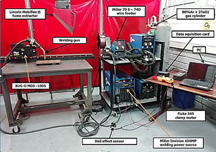
A welding power source Miller Invision 456MP with a Miller 70 S-74D wire feeder were used to run the testing welds. The welding gun was fixed on a Bug-O MDS-1005 Weaver Control Module, and the base metal was held below it, as shown in the photograph in Fig. 1. 70 mm-long bead on plate (BOP) welds were deposited on 9.53 mm thick 300 mm x 200 mm ASTM A36 steel plates, as shown in Fig. 13 (section 3.3).
The fixed variables used in the experiment (shown in Table 1)
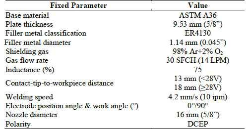
constitute typical parameter values for GMAW applications [17]. Nevertheless, as an MTM map must be constructed for each filler class and diameter, a single Ø0.045” (Ø1.2 mm) was selected in this study because of its wide commercial use. The independent variables were wire feed speed (WFS) and voltage setting in the power source. The WFS was varied from 100 to 500 in/min according to the filler’s manufacturer specifications; steps of 50 in/min were selected to provide enough resolution for the maps and in line with the variations used by several authors such as Pires (40 to 80 ipm) [22], Ferraresi (40 to 80 ipm) [25] and Heald (47 ipm) [21]. The voltage was varied from 14 to 34 V, which is a typical range in GMAW process; 1 V increments were selected for the same reasons considered for WFS. One hundred seventy-eight (178) welds were applied in this study in order to develop the MTM maps.
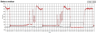
Current and voltage signals were recorded using a data acquisition system with a Hall Effect Current Sensor and a voltage divisor. The sampling rate was 5000 samples per second for every signal. The signals were captured for 10 s during each weld deposition and stored for subsequent analysis. A simple moving average with a window of three data (SMA-3) was used to smooth out signals and reduce noise. The beads were visually inspected to correlate weld quality to signals, transfer modes and instability boundaries.
The first step in signal analysis was MTM identification. In order to define the MTM for each pair of signals V and I, in addition to the respective analysis, we also considered the spatter level during welding, the sound of the arc, the direct visual observation of the arc and the visual inspection of the weld. This step was completed with a visual observation of droplet detachment during welding and the analysis of the recorded signals based on the shape of each signal and some of their statistical parameters. For short circuit and globular-short circuit MTMs, a frequency boundary of 20Hz was established based on values given by Scotti et al. [28], US Patent 9,808,879 B2 [27] and Annex C-3 of AWS D1.1 [18]. Root mean square (RMS) values of welding voltage and current were calculated from the recorded data. The maps were plotted with RMS current and RMS voltage because the usual welding meters (such as current clamps specified as “True RMS” and ammeters and voltmeters of welding power sources) use this kind of measurement.
In order to confirm the transition current range (205-215A) provided by the only reference that specified this datum for low-alloy filler metals [29], we carried out an experiment maintaining a fixed voltage value and slowly increasing the WFS from a very low (globular) value until, visually and auditorily, we defined that the MTM changed
from globular to spray. At that time, the WFS and the current obtained were recorded. This method was applied with seven voltage values between 28 and 34 V with a variation of 1 V.
3. Results and discussion
3.1. Metal transfer modes maps and IRMS vs. WFS curve
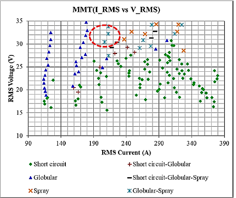
A MTM map, which is often referred as “transfer mode map”, is a Cartesian plane that represents the welding process parameters and shielding gas with the MTMs [28]. There are several versions of MTM maps with representations such as Visible Arc Length vs. Current [24], Welding Voltage vs. WFS [21] and, the most common, Welding Voltage vs. Current. In this study, we plotted three maps for the ER4130 filler metal using 98%Ar+2%O2 (VSETTING vs. WFS, VRMS vs. WFS and VRMS vs. IRMS) because they can be easily used by welding personnel to adjust their welding equipment or develop WPSs.
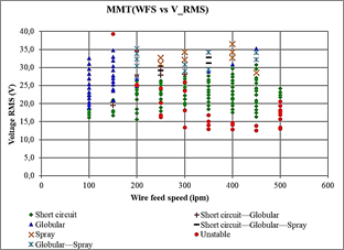
Figs. 2 and 3 show the VSETTING vs. WFS and the VRMS vs. WFS MTM maps, respectively, constructed in this work. Each mark on these maps represents a BOP weld applied with a particular combination of voltage and WFS. In order to define the MTM of each weld, we considered the spatter level during the weld application, arc sound, direct visual observation of the arc, visual inspection of the weld and, mainly, the analysis of current and voltage signals described in the following paragraphs.
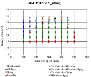
After the analysis of the 178 welds, six MTMs were identified in two groups: (1) the natural ones: short circuit (SC), globular (G) and spray (S); and (2) the interchangeable ones: short circuit-globular (SC/G), globular-spray (G/S) and short circuit-globular-spray (SC/G/S). Another kind of behavior was identified when the metal transfer was erratic and the arc was very unstable with long periods of interruptions; this was called “Unstable”, “Stubbing” or “Arc interruption”. As a result, there are eight different regions in the maps: 7 MTMs and stubbing.
Welding at WFS = 500 ipm was very difficult and the welds could only be obtained with voltages around 14-25 volts due to damage on the contact tube caused by the high arc power. The stubbing zone appeared and dominated the MTM map at the lowest voltages of each WFS, which meant that the arc length was very short. At low WFSs (100-250 ipm), the voltage to reach stubbing appears to rise (12 to 17V) with the increase in WFS; but, at WFSs greater than 250 ipm, this voltage starts to decrease (17 to 15V). At WFS=500 ipm stubbing occurred even at very high voltages around 21V.
The short-circuit zone, contrary to expectations, was very wide and predominated at almost all the WFSs evaluated here (100 to 500 ipm) between stubbing voltages and voltages as high as 29 V. The globular zone was wide too, but it was clearly found at the two lowest WFSs (100 and 150 ipm) and sporadically at higher WFSs; all of them at voltages greater than 20-23V. This is reasonable since, at low WFSs, there are also low currents below the transition current and the relatively high voltage enables the growth of the drops and their free flight. The spray zone was found at the highest voltages (33-34V) and medium to high WFSs (between 250 and 400 ipm), which is narrower than expected with an argon-rich shielding gas like 98%Ar+2%O2. Interchangeable MTMs were found, logically, at the boundaries between natural modes.
Some unstable signals in Fig. 3 (red dots) show particularly high values of RMS voltages because during the period of instability (as will be discussed in section 3.2.7) the voltage reaches very high values near the open circuit voltage (OCV) of the welding machine which is 90V. These periods with voltages near the OCV increase the RMS voltage.
Fig. 4 shows the VRMS vs. (Welding Current)RMS map and six MTM regions without the welds with unstable behavior. The red dashed line marks the spray zone defined by the manufacturer of the ER4130: 30-34V and 180-220A [30]. According to our results, these welding parameters are in the transition zone (globular-spray), but very close to achieving spray with just with a little more current.
The analysis of the voltage and current signals of the 178 welds is explained from section 3.2.1 to 3.2.7. This procedure is described to show how the MTM maps (i.e., VSETTING vs. WFS, VRMS vs. WFS and VRMS vs. IRMS) were constructed.
3.2. Voltage and current signal analysis
3.2.1. Signal analysis of short circuit MTM
The short circuit MTM in GMAW (named GMAW-S) is usually obtained at low voltage settings. Its typical signal behavior is recognized because the molten filler metal gets in periodic contact with the base metal, thus closing the electrical circuit; for this reason, it is called “contact transfer”.
Fig. 5 shows the voltage and current signals of the short circuit MTM in the 200 ipm/20V weld. The shape of this signal is similar to that of all the welds obtained in the SC Zone. The figure also includes a scheme that represents the sequence of metal transfer between the electrode tip and the weld pool according to voltage and current variations. At Instant 1, the electrode tip touches the molten pool and produces a short circuit that causes the arc voltage to drop to zero during a period called “short circuit time” (Instants 1 to 3); as a result, the constant voltage welding machine reacts, abruptly increasing the arc current up to very high values that depend on the system capacity (filler class and diameter, inductance and electrical characteristics of the machine), which in the case of ER4130/Ø1.1 mm were between 300 and 325 A; this level of short-circuit current increases the electromagnetic forces until they are enough to squeeze the filler metal (pinch effect) at Instant 3 and produce a metal transfer [17, 28]. After the metal is detached, the voltage begins to rise back to its nominal value of ~20V, which restarts the arc and gradually reduces the amperage (Instants 4, 5 and 6). Between Instants 4 and 6, a new metal drop is formed and grows on the electrode tip until it touches the puddle again at the end of the “arc period”.
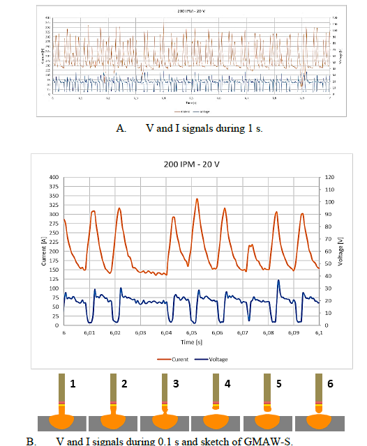
Instants 1 to 6 are repeated at a frequency that can be calculated from Fig. 5 A by counting the number of short circuits. In this case (200 ipm/20V), there were about 35 counts in 0.5 s, producing a 70 Hz short circuit frequency which exceeds the GMAW-S threshold of 20 Hz established as criterion in US Patent 9,808,879 B2 [27] and paragraph C-3.2.1 of AWS D1.1 [18]. The wave period could also be determined from Fig. 5 (T=1/f), that is ~0.014s during which the “arc time” (almost 80% of T) was much longer than the “short circuit time” (almost 0.20% of T). All the signals presented here were smoothed with a SMA-3.
3.2.2. Signal analysis of globular MTM
The globular transfer mode has two characteristics: (1) the formation and growth of drops of diameters 1.5 to 3 times greater than the electrode diameter, which are retained at its tip by the surface tension force; and (2) a very low drop transfer rate from 1 to 10 drops/s [28] that mainly fall due to the effect of gravitational forces and plasma drag in accordance with the theory of balance of static forces [22]; electromagnetic forces are negligible compared to their gravitational counterparts due to the low current intensities. In US Patent 9,808,879 B2, the authors established that a detachment frequency between 1 and 19 drops/s (which is 1 and 19 Hz) is a criterion to identify GMAW-G [27]. In this study, globular transfer was found with low and moderate values of WFS and voltages from medium to high, higher than those for GMAW-S, in order to have an enough arc length for the drop growth and falling in “free flight” without any short circuit, as shown in Fig. 6.
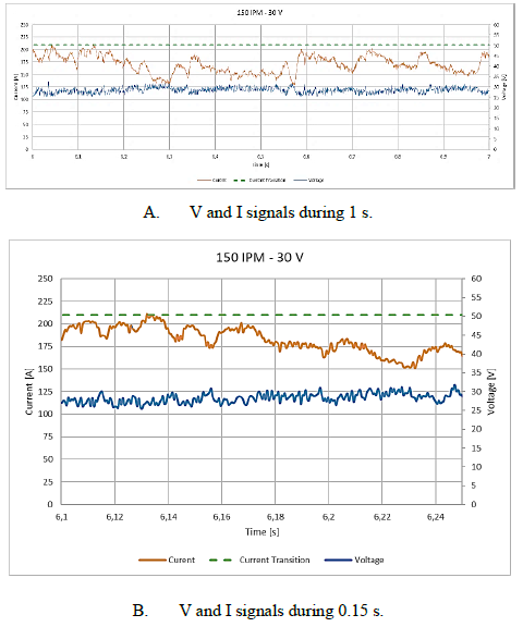
Fig. 6 presents the V and I signals of a weld applied with 150 ipm/30V that exhibited a globular MTM. Fig. 6A shows the signals in a time lapse of 1 s and Fig. 6B in 0.15 s. This signal shape is similar to that of the other signals obtained in welds that were located in the globular zone.
The green dashed lines mark the transition current (IT) at around 210-215A, which was found in the only available document with data for HTLA filler metals [31] and serves as a reference point to differentiate spray and globular MTMs. The current signal of this weld was always below the IT. It can be noticed that the V value remains almost constant at 28V ± 2V, which indicates that there are no short circuits. The current fluctuates because, during the drop growth, the arc length and, therefore, the voltage, are reduced, which makes the CV power source respond by increasing the current level; on the contrary, when the drop falls off, the arc length and voltage increase slightly, and the power source reduces the current. In most cases, globular MTMs cause large amounts of spatter, which reduce deposition efficiency and produce low-quality welds.
3.2.3. Signal analysis of spray MTM
The spray transfer mode is characterized by small droplets (whose diameters are smaller than the wire diameter) that detach from the electrode tip at a high frequency. This kind of MTM occurs at relatively high voltages and currents that exceed the so-called “transition current” (IT). Values below IT produce the globular MTM described in the previous paragraph and, above IT, spray MTM. There are other sub-modes of metal transfer both in globular and in spray such as pure or repelled globular and, for spray, drop or projected spray, streaming spray or explosive spray. However, an Electrical signal analysis does not allow discernment between these metal transfer sub-modes.
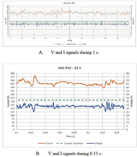
Fig. 7 shows the current and voltage signals for spray MTM corresponding to of the weld applied with 400 ipm/33V. Fig. 7A and 7B show the signals in 1 s and 0.15 s, respectively. Due to the higher drop formation rate and its small diameter, the acquired electrical signals shown smaller variations than those of globular and short circuit MTMs. The average amperage was 330 A ± 20A which is well above IT (210-215 A), and the average voltage was 33 V ± 2V. This means that the instantaneous power of the arc and, therefore, the intensity of the acoustic pressure [32] do not change much over time, which results in a very soft sound of the arc, in clear contrast with GMAW-S crepitation due to sudden changes in arc power.
3.2.4. Signal analysis of short circuit-globular MTM
Fig. 8 presents the signals of a short circuit-globular MTM of the weld applied with 250 ipm/29V. Fig. 8A and 8B show the signals in intervals of 1 s and 0.1s, respectively. In Fig. 8A, there are instants with short circuits (near zero voltages and very high amperages) that alternate with other moments where the V remains almost constant and the amperage, although fluctuating, stays under the IT. This is classified as an interchangeable MTM in which welding conditions allow two natural transfer modes to occur in a periodic sequence without direct interference by the welder or the equipment [28]. The frequency of the shorts, which in this case can be estimated at 18 Hz, is not enough to be considered GMAW-S and the fact that there are shorts implies that it is not pure globular but a mixture of MTMs.
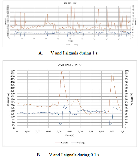
The frequency of shorts in the time lapses when the GMAW-S occurs (when the voltage drops to almost zero) can be calculated from Fig. 8A; during all these moments, the droplet frequency is between 30 and 50 Hz, which is typical of the short circuit MTM according to the threshold defined in several references [18, 27]. In the periods where the globular MTM take place, the current level is always below the IT which is around 210-215 A.
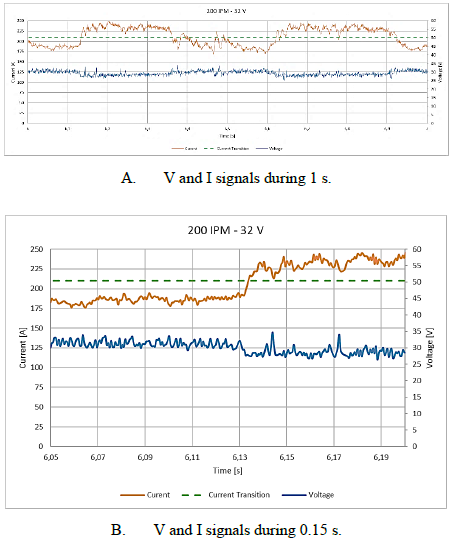
3.2.5. Signal analysis of globular-spray MTM
Fig. 9A shows the V and I signals of the weld applied with 200 ipm/32V that exhibits an interchangeable globular-spray MTM in an interval of 1 s; and Fig. 9B is a zoom-in on 0.15 s of that time. In Fig. 9A, the V is quite uniform and the current oscillates around the IT, sometimes below in a globular MTM and sometimes above in spray MTM. This kind of interchangeable MTM is located in the map (Fig. 2) between the globular and spray regions, concentrated in the welds with a WFS=200 ipm, which is precisely in the transition zone, that is, around the IT. It can be noticed that the globular precedes the spray until the conditions of arc voltage and, mainly, arc resistance which exhibit decreasing values) result in a higher welding current above the IT. Then, the opposite situation occurs and the transfer changes from spray to globular. This sequence is periodical which is a characteristic of every interchangeable MTM according to the explanations by Scotti et al. in their proposal for MTMs classification [28].
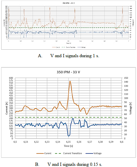
3.2.6. Signal analysis of short circuit-globular-spray MTM
Fig. 10 details the signals of the weld obtained with 350 ipm/33V that produced an interchangeable MTM with periodic successions of natural short-circuit transfer, a few moments in globular and long periods of spraying. This kind of behavior was expected in the transition zone between the three zones.
3.6.7. Signal analysis of instability and stubbing
Fig. 11 presents the current and voltage signals of the weld applied with 300 ipm/16V; their shapes are similar to those found at the lowest voltages required to obtain continuous welds with a stable arc. Fig 12A and 12B show the signals in intervals of 1 s and 0.15 s, respectively. Fig. 11 indicates three things: (1) for long moments (around 0.04 s) the voltage drops to almost zero and the amperage rises to values close to 450 A, which is an indication of a very long “short circuit” that, in GMAW-S, is around 0.003 s; (2) at other times, the amperage falls to very low values around 50-75 A; and (3) there is a periodicity in the occurrence of these abrupt changes in electrical signals of approximately 6Hz. The arc is very erratic and its fluctuations affect weld quality significantly. At the lowest voltages, this unstable mode or “stubbing” is characterized by a poor deposition rate and poor-quality welds that exhibit excessive convexity, lack of continuity and poor penetration.
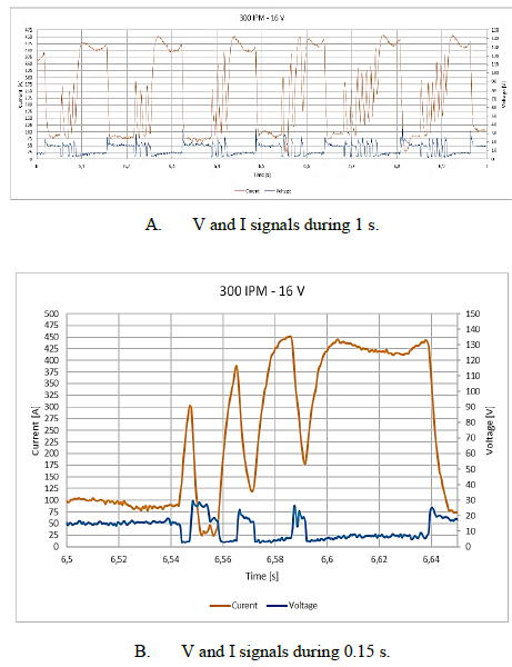
Stubbing is an instant of welding instability that occurs when the electrode fusion rate is lower than the WFS, therefore, the solid electrode tip comes into contact with the weld pool without proper material detachment and subsequent arc re-ignition [33]. This makes the welder feel that the weld gun is being pushed backwards in a series of successive hits [23] and increases the risk of lack of fusion due to an increase in weld pool freezing. The metal transfer takes place during the short circuits and, next, the electrode is attached to the base metal extinguishing the arc for long periods; for this reason, the welds are very discontinuous.
In other types of unstable signals, the arc is completely extinguished but in the opposite way: a very long arc with current at zero amperage and voltage reaching the open circuit voltage (OCV) of the Miller Invision 456MP power source which is ~90V, as shown in Fig. 12.
3.3. MTM map and weld appearance
Fig. 13 shows the test coupons produced with several WFSs (150, 250, 350, 450 and 500 ipm) and the surface appearance of the bead-on-plate (BOP) welds according to voltage variations. Poor quality and lack of continuity were noticeable in the welds applied with the lowest voltages and at WFSs between 150 and 250 ipm; above these WFSs, the welds exhibited excessive convexity and spatter.
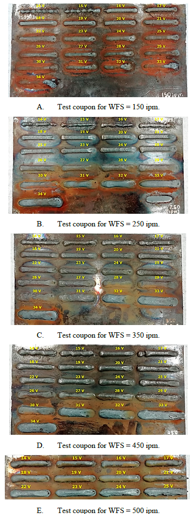
Almost all the welds applied with GMAW-S exhibited good quality with bead reinforcements around 1-3 mm. The globular welds also showed good quality but, when the arc voltage was increased, the quality was impaired and the beads showed spatter. The spray welds were very wide because of the high WFSs and V required to apply them; hence, their surface appearance is very smooth and uniform. For each MTM region detailed in the maps in Figs. 2, 3 and 4, the weld bead surface appearance was visually inspected and recorded with the corresponding pictures. Typical welds obtained with several combinations of WFS/V are included in the MTM map in Fig. 14 in order to visualize the quality by region. The poorest quality was obtained with the lowest voltages where arc instability and stubbing were present and the voltage and current signals showed a very erratic behavior (explained in section 3.2.7).
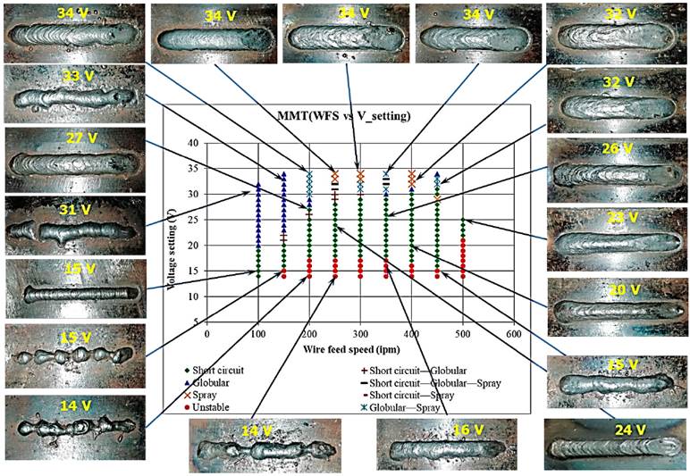
Source: The Authors.
Figure 14 MTM map with pictures of the surface appearance of the bead-on-plate welds.
The data sheet of the ER4130 filler says that spray transfer welds are achievable at 180-220A and 30-34V using 98%Ar+2%O2 [30], which is not fully in agreement with the findings of this study because, with this set of parameters, the MTM is in the transition zone (G/S) but very close to achieving spray with just a little more current and a CTWD>18 mm. This difference can be caused by different methods or devices used to define MTMs.
4. Conclusions
Three MTM maps for Ø1.14-mm ER4130 steel wire were constructed using 98%Ar-2%O2 as shielding gas and based on voltage and current signals: VSETTING vs. WFS, VRMS vs. WFS and VRMS vs. IRMS.
The spray zone found here was very narrow, contrary to the expectations, for this kind of filler metal and shielding gas rich in argon. Conversely, the short circuit zone was very wide and achieved with multiple combinations of welding parameters.
The spray described by the manufacturer of ER4130 (180-220A, 30-34V and 98%Ar-2%O2) is located in the transition zone with a globular-spray MTM, but it is very close to achieving spray with a little more current. The spray MTM is only achieved with CTWDs greater than 18 mm. This difference can be caused by different methods used to define MTMs.
The pictures of weld appearance superimposed on the MTM map show the regions with better quality.
Weld beads with good surface appearance were obtained with short circuit and spray MTMs, and even with the short circuit-spray. Globular welds exhibited spatter. Welds in stubbing areas with low voltages exhibited very poor quality and surface appearance.

