


 Inglés (pdf)
 Articulo en XML
 Referencias del artículo
 Enviar articulo por email
 Citado por SciELO
  Citado por Google
  Similares en
SciELO
Similares en
SciELO  Similares en Google
 Permalink
1. Introduction
During the last decades, the interest in generating clean energy by unconventional methods has grown due to the high electricity demand, especially in urban areas.
In this context, several strategies for the conversion of mechanical energy to electrical energy have been identified.
Saucedo et al. evaluated electricity generation from waves and generated electric power of 20V, from a magnetic wheel, to be used in the public transport system [1]. Besides, other authors proposed the generation of electrical energy using piezoelectric devices [2-3]. Furthermore, Márquez and Tlatelpa designed and built a power generator through a system of mechanical gears, chain drive, and alternator output to be used in the mass transport system in Mexico [4]. Thus, 747.5 W were generated from a single turnstile of the station "Indian Green", for one hour. Moreover, Ahmad et al designed and fabricated a power generator induced by the movement of a door to charge a smartphone; as a result, it generated a voltage of 11.54V, which was enough to meet the target [5].
In another case, Blanchette and Al-Haddad implemented a permanent magnet generator of a double rotor with a magnetic gear to collect wind power directly without mechanical conversions; as a result, a prototype of a compact generator of 2,5kVA was proposed, which could be coupled directly to the source [6]. Finally, Sepulveda designed and manufactured a power generator based on rotary piezoelectric, through a polygon-shaped gear. The power generator was built using the pair of the axle of the pedals of a gym’s static bike. A previous device was developed to feed the control circuit of the bike. Therefore, a power of 16mW was generated, for an average input of 300 revolutions per minute [7].
1.1. Framework
A gear is a mechanism used to transmit mechanical power from one element to another by rotating or reciprocating movements. These mechanisms can be formed by sprockets of different sizes that fit together, and through this mechanical plug, the movement is transmitted from the main shaft to the other complementary parts. The movement transmission is performed at a specific distance from the shaft.
Power generation mechanisms through magnetic induction date back to the nineteenth century, when Oersted discovered that an electric current could produce magnetic phenomena [8]. Faraday and Henry also noticed the previous finding, as they realized that a current is produced when a magnet is located near a circuit.
Faraday's law states that if an electrical conductor is placed in the presence of a magnetic field, the conductor will keep current if the system has a variable flow [9]. As shown in eq. (1), the induced electromotive force (EMF) will vary as fast as the flux of the magnetic field varies over time.
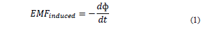
The flux ф of the magnetic field through all loops (N equal loops), is the product between the flux through one loop and the number of loops N. Being ф = NBA, the induced voltage variation is directly proportional to the number of turns
By measuring the induced voltage in the coil set, higher voltage could be observed when they were interconnected in series. However, handling neodymium magnet poles must be careful because the induced FEMs could be subtracted. Neodymium magnets (Nd-Fe-B) are composed of boron, iron, and neodymium, hence their metallic features. Since these magnets are characterized by being too easily oxidized, they are covered with a layer of varnish, zinc, or nickel.
The magnet poles influence the flow direction of the induced current. According to Faraday, the direction of the induced current is such that it opposes the flux variation since the area of the coil does not change, the flux is modified by changing the magnetic field.
Fig. 1 shows the magnet with its north polarity on the upper side, and south polarity on the lower side, so the field line enters through the south side.
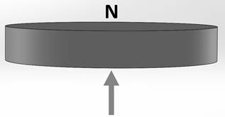
Fig. 2 shows the opposite case: the upper face has a south polarity and the other one has a north polarity; consequently, the flux line comes out of the north face, following the convention of a magnet's magnetic field lines.

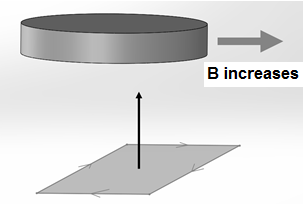
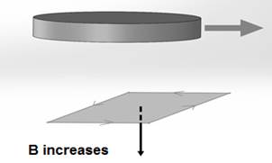
Fig. 3 shows the direction of the magnet movement when it approaches the coil: the magnetic field increases as the coil loop area concatenates more magnetic flux. Therefore, the coil will induce more current, which in turn will produce a more magnetic field. In this way, the coil will be able to counteract the magnet's outer magnetic field.
Source: The Authors.
Figure 3 Direction of the induced current in the coil when the field increases in the shown direction.
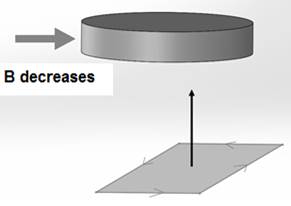
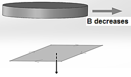
Fig. 4 shows the passage of the south polarity magnet face, over the coil turn. In this case, the magnetic field decreases in the direction shown in the figure, and the direction of the current is inverted concerning the previous cycle.
Source: The Authors.
Figure 4 Direction of the induced current in the loop when the field decreases in the shown direction.
Fig. 5 shows the approximation of the magnet face with a north polarity that will be facing the coil. This will increase the magnetic field on the loop, in the downward direction; therefore, to counteract it, it generates a current in the shown direction.
Source: The Authors.
Figure 5 Direction of the induced current in the coil when the field increases in the shown direction.
Fig. 6 shows the same effect, but now with an opposite direction current, due to the change of the magnet face polarity.
Source: The Authors.
Figure 6 Direction of the induced current in the coil when the field decreases in the shown direction.
Considering cases shown in Fig. 1-6, the induced current in the loop follows a sinusoid waveform with P period, as evidenced in Fig. 7.
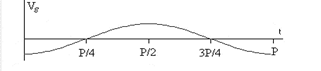
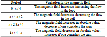
Regarding Fig. 7, P is the period of the magnetic field. The field variations in P are specified in Table 1.
2. Materials and methods
The methodological design of the research was divided into two phases. The first consists of performing a statistical study about pedestrian entrance and exit at Escuela Colombiana de Ingeniería Julio Garavito. The study was carried out from January 15th, 2017 to December 15th, 2017. It allows performing a characterization of people’s influx behavior, time bands, use of turnstiles for pedestrian access, torque value, time, and turning distance. The turning speed was calculated considering the time and turning distance. Afterwards, the power was obtained from the calculated turning speed and force. It is important to remark that the power value is an initial condition for the design of the two energy conversion mechanisms. In this way, the average speed of the turnstile was 15.3846 rpm due to the staff entry/exit, and the exit speed of the dynamo was 1583.07 rpm.
According to eq. (2), to calculate the power, the force applied to the turnstile arm was required to be measured.
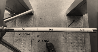
Force was measured with a dynamometer. To identify the support point used to move the turnstile, this variable was considered in the statistical study about the entrance and exit of the staff at the Institution.
As a result, it was found that 90% of the users support the central segment D2 (Fig. 8) to push the arm, and an average force of 23.6N was measured on this point.
Subsequently, the generated torque was calculated using eq. (3) [10], this value was 3.27 Nm, and it allowed us to know the dynamic moment exerted by a motor (which in this case is the user) on the power transmission shaft (the turnstile arm).
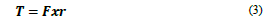
Where F is the force in Newton, and r is the average turning radius of the tourniquet arm.
Then, the second phase of the methodological design consisted in dimensioning, designing, simulating, constructing, testing, and adjusting the mechanisms using magnetic induction and through gears, for the generation of electrical energy.
The mechanism by magnetic induction was based on the construction of a mobile wheel prototype (40cm diameter and 1cm thickness), with equal magnets of 30mm radius and a height of 3mm. Furthermore, it rotated on a specific axis, in which two fixed square (40cm x 40cm, and thickness of 1cm) structures with multilayer coils (3cm) were located. Coils were included for the electricity production.
The prototype was made from wood, and enameled copper coils; 18-gauge AWG were also produced. Coils had an iron core and a radius of 2.54 cm. The two fixed square structures were coupled to the movable wheel on a common axis. These structures were simulated in SolidWorks.
Fig. 9 shows the moving wheel with the neodymium magnets.
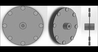
The two fixed square structures shown in Fig. 10 contained the group of coils arranged circularly.

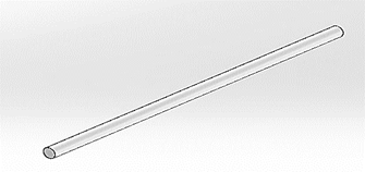
The common axis of the mechanism by magnetic induction consisted of an aluminum tube of length 540mm (Fig. 11).
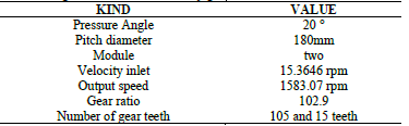
The design of the mechanism using gears started from the gain that the system must have, considering that the average speed of the turnstile (due to the entrance of users) was V1 = 15.3846 rpm, and the exit speed of the dynamo was V2 = 1583.07 rpm. Considering previous data as input information, and following gear design equations, the results shown in Table 2 were obtained.
Eight tests were carried out with each of the mechanisms. For each test, the power difference in RMS values was measured at the output of the mechanism on a load resistance of 20Ω (LED bulb for the gear mechanism) and 100Ω (for the magnetic induction mechanism). The values or scores obtained were recorded, coded, organized, and transferred to a table in Excel. The calculation was made by computer, and the data analysis was done through descriptive statistics. The voltage variable was analyzed, and afterwards its relation to power was obtained for the same outlet point. The mean value was the used measure related to a central tendency because this statistical parameter is the most appropriate for levels of measurement by intervals. Median values were calculated, as the arithmetic average of recorded measurement distribution.
Since this measure is sensitive to extreme changes, atypical values were eliminated. The spread of the data was calculated using measures of variability: standard deviation and variance.
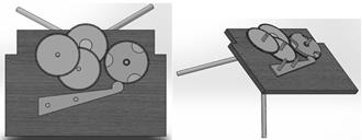
Fig. 12 shows the integration of the parts in the system.
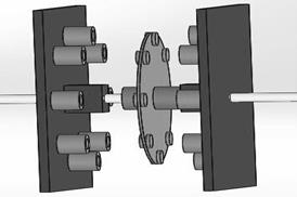
Fig. 13 shows the SolidWorks simulation of the gear mechanism integrated into the tourniquet.
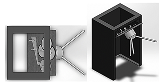
Fig. 14 shows the first section of the mechanism and the composed gear train.
3. Results
The statistical analysis of the database related to the number of users, and the time of pedestrian entrance and exit at the Institution, allowed us to identify that on Monday, from 8:00 a.m. to 9:00 a.m. the largest influx of people is presented. Considering previous findings, turnstile 3 was the most used, which generates an average of 3.18 rpm in continuous operation.
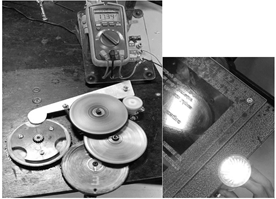
By connecting the mechanism based on the mechanical gears to the turnstile and loading it with a 12W LED bulb (Fig. 15), electric power was generated in a range of 12v to 17v. The statistics of the eight tests yielded an average median of 15v, an average voltage of 15v (average power of 12W), an average standard deviation of 1.56, a variance of 2.43, a maximum value of 17v, a minimum value of 12v, and range of 5.
The mechanism by magnetic induction (Fig. 16), connected to tourniquet 3 and loaded with a bank of resistors R = 100Ω, generated a voltage in the range of 7V to 11V. The statistics of the eight tests yielded an average median of 9v, an average voltage of 10v (average power of 1W), an average standard deviation of 1.41, a variance of 1.99, a maximum value of 11v, a minimum value of 7v, and range of 4.
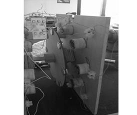
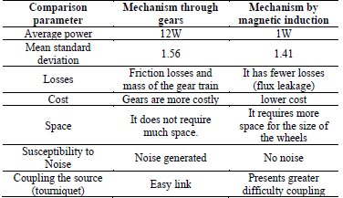
Table 3 compared both mechanisms under some parameters.
4. Analysis of results
Due to the magnetic flux equation ф = NBA, the induced voltage depends on the coil core for the mechanism by magnetic induction. The flux is directly proportional to the amount of magnetic induction B = uH; which in turn is directly proportional to the permeability of the coil core material (μ) [12]. Hence, as coil core material increases, the magnetic flux density also increases, as well as the flow, and induced voltage (while working in the unsaturated core region). In the context of this research, and as shown in Fig. 17, the core was constructed in a laminar way to avoid Edy currents, and it was made out of a material with high μ (recycled sheets from the core of a transformer). To concatenate high flux was not possible due to the lack of uniformity in the manual construction of the nucleus.

Another reason why a low induced FEM was obtained by this mechanism was the small size of the Neodymium magnets, and the large separation distance between them, which did not allow efficient use of the high coercivity of the magnets [8] and the area of the wheels (see Fig. 18).
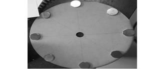
Source: The Authors.
Figure 18 Arrangement of magnets in a wooden base diameter of 29 cm spaced at 45 °.
According to Faraday, the direction of the induced current is such that it opposes to the flux variation since the area of the coil does not change, the flux is modified by changing the magnetic field. In this context, there are two determining factors for the correct operation of a mechanism based on magnetic induction: (1) to correctly identify the poles of the magnets and (2) to achieve the interconnection between the coils, since the direction of the induced flow and the winding direction must be considered. In this way, the induced voltage polarity is determined, and the interconnection between the coil terminals is performed to cause voltage overlap [9].
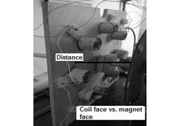
Even though it was all fulfilled, a low induced voltage was obtained. It could be a consequence of the lack of coupling between the magnets and the coils in the magnetic mechanism (equalization or confrontation) and a shorter separation distance between them (see Fig. 19).
The size of the wheels could be re-evaluated, reducing their radius to achieve a more stable system and occupying less space. To increase the speed, and the generated voltage, it is recommended to couple the design mechanisms. Thus, a greater voltage is generated by overlapping (coupled one to the other in the same system), compared to mechanisms working independently.
Regarding the quantification of generated electrical energy, results show an average of generated electrical power of 12W and 1W for the mechanism based on gears and magnetic induction, respectively. Considering the goal of feeding the University access control circuit, the generated energy is enough, and its use is applicable to the isolated generation of electricity for the independent consumption of a circuit. It could be improved by connecting the mechanism in parallel.
Nevertheless, the author acknowledges that the obtained output powers of each mechanism are not high. It is partly because of the mechanical source (turnstile), and the low level of the mechanism efficiency. The difference between generated powers by each mechanism is due to their own features, mechanical loss, due to Foucault, hysteresis, and Joule effect.
For instance, for the mechanism based on magnetic induction, no modification of the coil positions and angles was carried out, nor a reduction of the distance between coils and magnets. Due to the concentration of flux lines, the mentioned modifications could reduce the dispersed flow and increase the magnetic induction, and therefore, a more electromotive force (EMF) could be generated.
As future works, it is important to consider that the improvement of the magnetic flux exploit is possible by performing an analysis of finite elements and modifying different constructive parameters of the designs.
On the other hand, the operational feasibility of this research is based on the statistical study of the staff entrance and exit at the University, collected during the two semesters of 2017. Meanwhile, the gradual increase in the number of new students during these last three years can be translated into more generated electrical energy. The study and experimentation of new alternatives for the generation of clean energy must be remarked, as it will allow reducing the dependence on the use of fossil fuels.
5. Conclusions
Based on the coupling of the two mechanisms, this research demonstrates the technical and operational feasibility of converting mechanical energy to electrical energy, which was generated from users’ entrance and exit
The geared electrical power generation mechanism generated more power (12W) than its counterpart by magnetic induction (1W).
The power generation can increase, if the multiplication factor of the speed is increased, the above could be achieved by coupling the two mechanisms into one.
The mechanism by magnetic induction can generate more electrical energy if the flow is better coupled. This is achieved by decreasing the separation distance between the magnets and the coils and matching the location of the magnets with respect to the coils (facing faces) in the structures that contain them (wheels).
The obtained energy at the output of the two mechanisms was not regulated, which is an important condition to be considered, for instance, to power the turnstile's electronic circuits.
From this research experience, it can be concluded that the energy conversion based on magnetic induction is not suitable for the generation of electrical energy in large amounts.

