English (pdf)
 Article in xml format
 Article references
 Send this article by e-mail
 Cited by SciELO
  Cited by Google
  Similars in
SciELO
Similars in
SciELO  Similars in Google
 Permalink
1. Introduction
Capacitors are used in distribution systems in order to improve the power factor, to reduce the losses, and to improve the voltage profile of the circuits. The correct placement and sizing of the capacitors on circuit's buses, as well as their control in time are very important to obtain maximum benefits.
On the other hand, it is known that the presence of capacitors in a circuit contaminated by harmonics can bring the appearing of resonances. This phenomenon is responsible for the magnification of the harmonic distortion indices and the possible overload of capacitors.
Masoum [1] presents an iterative algorithm for the optimal sizing and placement of fixed and switched capacitor banks. The method combines the maximum sensitivities selection of candidate nodes with local variations, but do not assure optimal solution. Two new contributions are proposed by Masoum [2,3]. The first employs a fuzzy-sets approach for selecting the optimal placement and sizing of fixed capacitors. The second, presents a genetic algorithm (GA) for the power quality improvement and optimal placement and sizing of fixed capacitors.
Yu [4] presents a particle swarm optimization (PSO) approach to optimal capacitor placement. The method considers different load levels. Carpinelli [5] presents a method based on the sequential placement of capacitor units; process that cannot assure optimality of solution. Considers unbalance and several load levels.
Khalil [6] employs a binary-PSO to determine the placement of fixed and switched capacitors, while Ladjavardi [7] introduces another GA application with fuzzy-reasoning to manage as objectives the suitability of THD, voltage, and cost, while considers a single load state.
A discrete version of PSO is presented by Eajal [8] to minimize total cost while the THD complies with bounds. The method places fixed capacitors on unbalanced systems. Another PSO application is introduced by Taher [9] for fixed capacitors that uses penalty functions to manage constraints.
Mohkami [10] proposes a bacterial foraging (BF) oriented by PSO for placing fixed and switched capacitors. The analysis of sensitivities is used to select candidate nodes. Fuzzy multi-objectives are: cost, THD and voltage deviation.
Chang [11] presents a fuzzy logic and immune algorithm (IA) for placement and sizing of capacitors. The suitability of losses index, voltage, THD, and locations are modeled as fuzzy membership functions. The candidate locations are selected and the capacitors’ sizes are calculated by the IA.
The non-dominated sorting genetic algorithm (NSGA-II) is used by Segura [12] to minimize the total cost and the quadratic sum of harmonics’ voltages differences in respect to the base case. This contribution introduces the resonance index (RI) constraint to avoid the overstress of the capacitors. The methodology assumes the recommended current-distortion limits of IEEE Std. 519 [13] as the harmonics of the non-linear loads. Gonzalves [14] uses the extremal optimization (EO) heuristic to solve the capacitor placement taking into account resonance constraints. This method considers a single load state.
A hybrid honey bee colony algorithm is presented by Taher [15]. The method minimizes losses and unbalances while maintaining voltage and THD in an acceptable range. A penalty free GA is employed by Vuletic [16] for solving the capacitor placement with different load models. This approach considers fixed and switched capacitors.
The placement of fixed and switched capacitors with the NSGA-II is presented by Azevedo [17]. The formulation minimizes: cost, voltage deviation and THD. Also, Onaka [18] uses the NSGA-II for minimizing cost and voltage-deviations. Constraints of THD and IHD are evaluated, but a resonance index RI is employed to consider the capacitors’ overstress limits after the optimization ends.
A multi-swarm particle swarm optimization (MSPSO) algorithm is proposed by Ayoubi [19]. A sensitivity analysis is applied to find candidate buses and the size and location of capacitors are optimized by MSPSO. It supports different load levels employing fixed and switched capacitors.
The Chu-Beasley GA is employed by Semensato [20] to the placement of capacitors in unbalanced circuits with one load state. Recently, Moghadam [21] has presented a new application of NSGA-II to minimize: cost, THD and voltage deviation. A single load state is considered.
Some of the contributions [1,10-12] use the losses sensitivity of nodes to obtain a reduced set of candidate nodes to locate the capacitors. This is a proper technique to simplify the optimization, but these locations set cannot be too small.
The consideration of several load levels with different cost and duration is fundamental to evaluate the capacitor placement effects on losses, voltages and other power quality constraints. However, some contributions [2,3,7-9,14,20, 21] analyze only one load state.
The IEEE Std. 519-2014 states recommended maximum values of THD and IHD to be complied. However, with the exception of a few contributions [11,16-18], only the THD constraints are considered.
The IEEE Std. 18-2012 [22] states the maximum permissible values for: rms voltage, peak voltage, current and reactive power of capacitor banks. Some references [12,18] try to avoid the overstress of the capacitors by introducing the resonance index, but only the references [16,17] fully addressed the required constraints.
This work presents a substantial improvement of the variables’ inclusion and interchange algorithm (VIIA) for capacitors placement [23] that considers circuits with harmonic distortion. Several load states are considered and fixed and switched capacitors are employed in optimization. All the pertinent constraints of voltage magnitude, THD, IHD, and of overstress of capacitors are implemented. The here defined global harmonic-distortion index states the distance to the feasibility or the infeasibility of a solution with respect the harmonic distortion constraints. The inclusion in the sequential quadratic programming (SQP) sub-problem of an inequality linear constraint on this global harmonic-distortion index, allows the determining of solutions that comply with the harmonic distortion related constraints. A comparison of the solutions of various examples obtained by the presented method with the best solutions obtained by the Matlab’s GA shows the effectiveness of this method.
2. Optimization problem
This work formulates the capacitor placement problem in distribution circuits with harmonic distortion as the selection, placement, and control in time of the set of capacitor banks that maximizes the saving in total annual cost.
The constraints of minimum and maximum voltage, as well as the pertinent constraints of power quality and of capacitors' overstress are considered.
2.1 Independent variables
The load’s daily variation is represented by T states of load sorted in ascending order (normally: light, nominal and peak load). A capacitor that is switched-on in the t-load state will remain connected from this state up to the peak load state.
The capacitors can be placed in any of the N nodes of the circuit and can be switched-on in any of the T defined load states. Thus, there exist L=N·T possible locations for placing the capacitors. The location of index i represents the node n i and the switch-on time t i of a single capacitor bank.
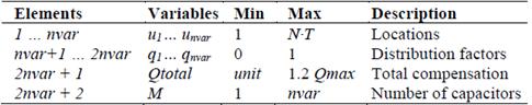
The independent variables of the problem are the vectors x and u of length (Mx1) that represent respectively the sizes and locations of the capacitors. The elements of u are integers limited to the number of the possible locations, while the elements of x are the standard sizes of the capacitors placed in the u locations.
2.2 Objective function
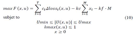
The objective function of the optimization problem is the maximization of the total cost saving F(x, u).

Where c t is the cost of losses in the load state t ($/kW) and ∆loss t (x, u) is the saving of losses in the t load state due to the installation of capacitors with sizes x on the u locations. The annual cost of capacitors is represented by the units cost kc($/kvar), and the fixed cost per capacitor bank kf ($/bank). Besides, M is the number of capacitors.
2.3 Constraints
The voltage constraints assure that module of voltage U in every node and load state (n,t) will fulfill the desired lower and upper bounds Umin and Umax.

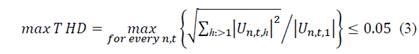
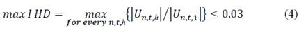
Taken into account the recommendations of the IEEE Std. 519-2014, other voltage quality constraints are applied on the maximum distortion indexes THD and IHD in every node, load state and harmonic (n,t,h). These indices must comply with 5% and 3% limits respectively in medium voltage level.
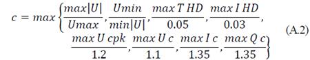
In addition, other constraints are stated to avoid the overstress of the capacitors by complying with recommended bounds by the IEEE Std. 18-2012. This standard state the limits of stress of the capacitors: the maximum peak voltage (Ucpk), the maximum rms voltage (Uc), the maximum current (Ic) and the maximum reactive power (Qc). The maximum of these indices for all capacitors must comply with:

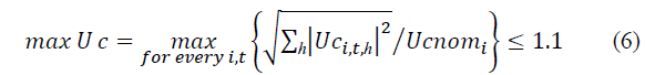
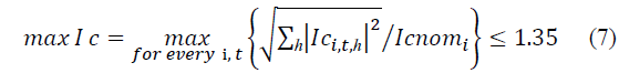

Where sub-index i represents the capacitor bank.
In order to simplify the evaluation of the harmonic related constraints, a single normalized index of maximum distortion is proposed such that:
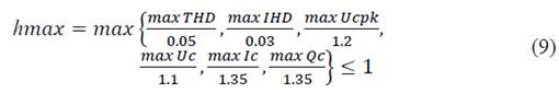
If the hmax index is equal or lower than unity, all the constraints of power quality and of capacitors' overstress are fulfilled.
2.5 Problem formulation
Finally, the optimization problem can be stated as the determination of the number of capacitors M, the u-locations (node and switched-on time) and the x-sizes that solves the problem represented by:
3. Sequential quadratic programming approach
For a given number of capacitors and u-locations, the capacitors’ optimal x-sizes are obtained by applying the Sequential Quadratic Programming (SQP) method. This method solves a nonlinear optimization problem by solving a sequence of optimization sub-problems, each of which is formed by a quadratic objective function subject to a linearization of the constraints of the original problem.
3.1 Sub-problem’s quadratic objective function
The quadratic sub-problem’s objective function is obtained from (1) by considering a linear approximation for the variations of voltages with respect to the Δx-capacitors’ sizes variations.
As losses at harmonic frequencies are negligible with respect to the losses at fundamental frequency, only the fundamental frequency losses saving is considered in the presented model. The fundamental frequency power losses saving at the t load state is the difference of the losses before and after the capacitors placement.

Where U t and ∆U t are column vectors (Nx1) that represent the fundamental frequency voltages without capacitors and their variation by the effect of the capacitors at the load state t. Besides, G is the fundamental frequency conductance matrix of the network. The matricial operation z* denotes the transposed conjugate of the matrix z.
The variation of fundamental-frequency voltages ∆U t due to variations of the capacitors of sizes x can be approximate by the linear relation:

The elements of the matrix J t of size (NxM) are derivatives of the voltage at load state t in node n respect the susceptance of the capacitor installed in node m.
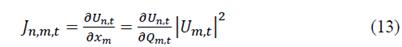
The derivatives of voltage in the node n with respect to the variation of the reactive power in the node m are extracted from the inverse of the Jacobian matrix of the Newton-Raphson load flow.
Substituting (12) in (11) is obtained an approximated quadratic model for the reduction of losses at the state t.
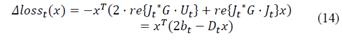
Integrating the saving of losses in all load states, the quadratic objective function of the sub-problem can be approximated by:

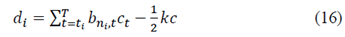
The elements of vector d are determined for the capacitor i placed in the node n i and switched-on in state t i , as:
The elements of A-matrix are determined by the interaction of the capacitor i and the capacitor j (which is placed in the node n j and switched-on in state t j ) as:

3.2 Sub-problem’s linear constraints
Although the harmonic voltages can affect the rms voltage magnitude on the nodes, normally this influence is very reduced if there are no resonances in the circuit. In order to simplify the representation of the voltage constraints, only the fundamental frequency voltage will be considered.
Substituting (12) in (2), the maximum and minimum voltage constraints at load state t can be expressed by:

Where the elements of the matrix W t are determined by:

In general, if U represents the vector of voltages in every nodes and load states, the minimum and maximum voltage constraints can be expressed as:


In spite of the nonlinearities related with the harmonics penetration in a network with capacitors installed, in this work is developed a linear approximation of the previously defined harmonic distortion hmax-index (9). This approximation is based on determining the variations produced in hmax when each variable (capacitor) of the solution is increased one standard unit while the others remain the same.
If the vector x represents the sizes of the installed capacitors, a variation Δx that makes that the solution complies with the harmonic distortion bounds must be limited by the linear constraint:

Each element Jh i is the ratio of the variation of the harmonic distortion index Δhmax(x) with respect the variation Δx i of the variable x i:

The obtaining of each Jh i element requires the use of the harmonics penetration function to calculate the harmonics distortion index when only the variable x i is incremented in one standard unit.
3.3 Sub-problem’s representation
The quadratic programming model of this sub-problem is represented by:
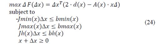
The SQP method solves the problem (10) by the successive determination of the best feasible variation Δx that solves the quadratic sub-problem (24). The first iteration begins with x = 0 (without capacitors) and next iterations increase x by x + Δx. Only a few iterations are needed to obtain convergence of x.
4. Algorithm of optimization
The determination of the x-sizes of M-capacitors in the given u-locations is solved by the SQP method. However, the locations (switched-on time and placement) and the number of capacitors must be determined by searching within the possible sets of variables (locations) that can integrate a solution.
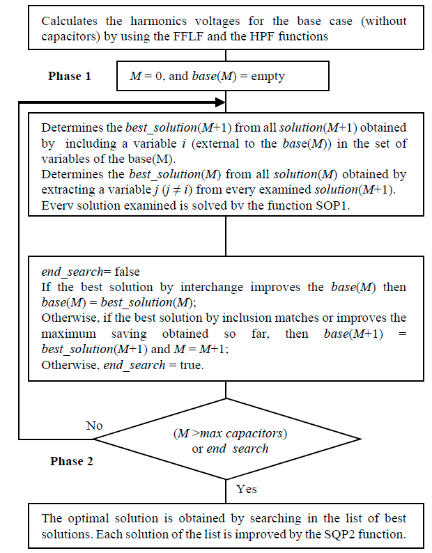
The VIIA is composed by two consecutive phases: 1) the search of solutions; and 2) the selection of optimal solution.
In the search phase, the algorithm examines a reduced subset of the possible sets of variables (solutions). The x-sizes corresponding to a given u-locations are obtained by solving the approximate quadratic sub-problem (24) of the base case by the function SQP1, which implements only the first iteration of the SQP method.
The transit from one set of variables (solution) to another is based on their relative merit, which is measured by the penalized objective function value Fp(x). The best 500 solutions examined in this search phase are stored in the best solutions list.
Once the search phase is finished, the list of best solutions is sorted in descending order of the non-penalized objective function value F(x) and in ascending order of the harmonics distortion index hmax(x).
These 500 solutions have been obtained by only the first iteration of the SQP method. Thus, they are approximate solutions that have not been tested by the fundamental frequency load flow (FFLF) and the harmonics penetration function (HPF). Then, each solution of the list is improved by the function SQP2, which implements the final iterations of the SQP method, until a convergence of the capacitors sizes is achieved. The best of the obtained solutions is selected as optimal.
4.1 Description of the search algorithm
The search algorithm begins from the empty solution base(0) (number of capacitors M = 0). The solution grows in number of variables (capacitors) from the base(0) solution up to the solution with the maximum Fp(x). In each step, departing from the base(M) of M capacitors, a new solution is obtained by adding a new variable (location) to the base(M) or by interchanging a variable of the base(M) solution with a variable external to this solution. This algorithm is described by the Flowchart 1.
If the number of possible variables (locations) is L. One iteration of the presented search algorithm departing from the base(M), requires the evaluation of (L - M) solutions by inclusion of a variable and of (L - M)M solutions by interchange of variables. Thus, when the number of possible variables is high or the number of capacitors grows, the number of solutions to be evaluated is high.
The experience of use of the presented algorithm has proven that results are good enough if just a sub-set of the variables of a solution(M+1) is tested to obtain solutions of M variables by interchange.
In that way, the variables in a solution(M+1) are sorted in ascending order of their importance (size of the capacitors) and only the first out (out < M) variables are tested for extraction. In the presented implementation of the algorithm, out = 1 for solutions with low harmonics distortion (hmax(x) ≤ 0.95) and out = 4 otherwise.
On the other hand, the number of possible variables L can be reduced by preselecting a subset of nodes or a subset of load states. In the presented implementation, only 40 nodes are preselected for capacitor placement in each load state. The selection is based on the saving obtained by the capacitor placed on node i and switched-on at t-load state, that is, F i,t = d i,t 2/A i,i,t . In that way, the maximum number of variables L ≤ 40T is independent of the circuit’s size
The presented algorithm, including the FFLF for radial distribution systems, as well as the HPF, have been implemented in Matlab R2017a.
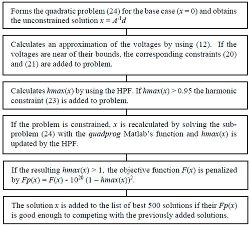
4.2 Algorithms of functions SQP1 and SQP2
For a given set of variables, the function SQP1 calculates an approximated solution x for the problem (10) by solving the sub-problem (24) (first iteration of the SQP method). The calculated objective function is used by the search algorithm to rank the solution.
The algorithm of the function SQP1 is described by the Flowchart 2.
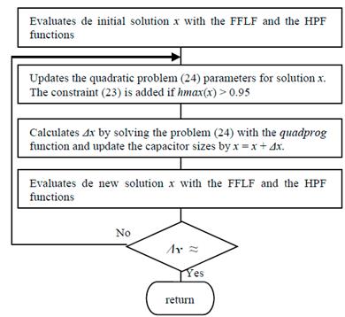
On the other hand, the function SQP2 improves the approximate solution x by repeating the final iterations of the SQP method until convergence is found. This function employs a fundamental frequency load flow and a harmonics penetration function to determine exactly the objective function value F(x), the voltages of all frequencies and the harmonics distortion index hmax(x).
The Flowchart 3 describes the algorithm of function SQP2.
5. Examples of application
In order to test the presented methodology, four known radial distribution systems of: 33, 34, 69 and 85 nodes are used. The data of the 12.66 kV’s circuits of 33 and 69 nodes are presented in the reference [24], while the data of the 11 kV’s circuits of 34 and 85 nodes are reproduced in the reference [25].
In all the following examples, the circuit operates in three load states of 0.5, 1 and 1.6 times the nominal load, with duration of 2000, 5260 and 1500 hours/year respectively. The losses cost is c t = $0.06/kWh in all load states and the annual cost of capacitors is calculated with kc = $3/kvar and kf = $1000/bank. A maximum of 15 capacitor banks composed of standard units of 150 kvar can be installed.
All circuits are supplied by a voltage source with 250 MVA of short circuit power with ratio X/R = 10. The source voltage is nominal with certain harmonics content represented by the harmonic spectrum of Table 1.
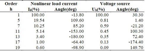
All loads are modeled as constant active and reactive power at fundamental frequency, while at harmonic frequencies; the linear load is modeled by the series RL circuit [26] and the nonlinear load current is represented by the harmonics’ spectrum of Table 1.
Two types of capacitors placement problems are solved in the examples: a) a voltage-constrained problem that assures a minimum voltage of 0.9 pu for solutions; and b) a voltage-unconstrained problem. In all cases, the solutions proposed by the presented search algorithm are compared with the best solutions determined by three consecutive runs of the genetic algorithm implemented in the ga function of Matlab R2017a.
To obtain good solutions for the examples with the GA, a large population of 1000 individuals and a maximum of 300 generations was used. Other data of the GA’s configuration are presented in appendix. The results of the GA in all presented cases are the best solutions found in three consecutive runs of the algorithm.
All examples were solved in a Intel(R) Pentium(R) CPU P6100 @ 2.00Ghz -2.00Ghz and 8.00 GB RAM. In that way the computation time of all runs can be compared among them.
5.1 Minimum cost optimization in the circuit of 33 nodes
The circuit of 33 nodes have a total load of 3715 kW and 2300 kvar. In the example, all the load in nodes 24, 25 and 30 is nonlinear, which represents the 28% of the total active load and the 43% of the total reactive load. The results of the optimization of this example are presented in Table 2.
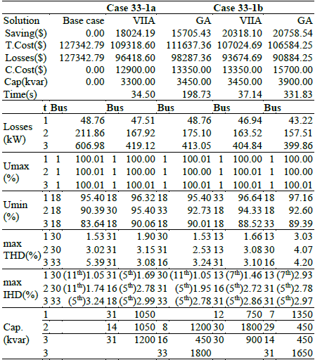
The base case (without capacitors) does not comply with the IEEE-519 recommendations because the maximum THD = 5.39% and IHD = 3.24% are outside the limits in the peak load status.
The first case analyzed (33-1a) includes the constraint of minimum-voltage of 0.9 pu. The proposed solution improves the GA’s solution in 14.8% by using the 95.7% of capacitor units. The presented algorithm obtains the solution in only the 17.4% of the GA’s computation time.
In the second case (33-1b) (voltage unconstrained), the proposed solution is inferior in 2.1% respect the GA’s solution. The proposed solution uses the 88% of capacitors’ units and is obtained in just an 11.2% of the GA’s computation time.
5.2 Minimum cost optimization in the circuit of 34 nodes
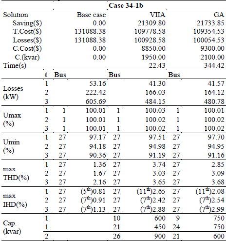
The circuit of 34 nodes have a total load of 4636.5 kW and 2873.5 kvar. As the minimum voltage of this circuit is greater than 0.9 pu, there is no difference between the constrained voltage solution and the unconstrained voltage solutions. Thus, the solutions of two different voltage-unconstrained examples are presented.
In the first example (34-1b) with results shown in Table 3, the 50% of load in nodes 17, 21 and 26 is nonlinear. This means the 7% of total load. However, the base case complies with the power quality constraints. The proposed solution is 2% inferior respect to the GA’s solution. However, this solution is obtained in only the 6.5% of the GA’s computation time. Three banks are proposed with the 92.9% of the capacitor’s units used by GA’s solution.
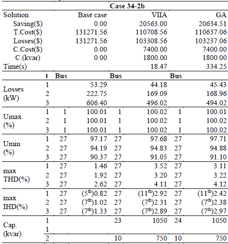
In the second example (34-2b) with results shown in Table 4, the 20% of load in nodes 17-26 is nonlinear. Thus, the 10% of total load is nonlinear. Although the harmonic distortion is incremented, the base case complies with the IEEE-519’s distortion limits. The proposed solution is only 0.35% inferior to the GA’s solution but is obtained in just a 5.5% of the computation time employed by the GA.
5.3 Minimum cost optimization in the circuit of 69 nodes
The circuit of 69 nodes have a total load of 3801.39 kW and 2693.6 kvar. Two different examples are analyzed with concentrated and distributed nonlinear loads.
In the first example (1), which results shown in Table 5, the 50% of load in nodes 49, 50 and 61 is nonlinear, which represents the 26% of total load.
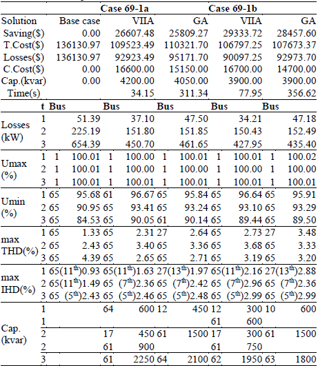
This example complies with the IEEE-519’s harmonic limits, but the maximum THD reaches the 87.7% of their bound in the peak load state.
The solution proposed for the constrained case (69-1a) improves the GA’s solution in 3.1%, uses the 103.7% of the total capacitor units and is obtained in only the 11% of the GA’s computation time. In the second case (69-1b), the proposed solution is superior in 3.1% respect the GA’s solution and is obtained in the 21.8% of the GA’s computation time.
In the second example (2), which results offered in Table 6, the 50% of load in nodes 49, 50 and 61, and the 10% of load in the rest of nodes is nonlinear, which totalizes the 31% of total load. This base case complies with the IEEE-519’s recommendations, but the maximum THD almost reach the IEEE-519’s recommended limit of 5% in the peak load status.
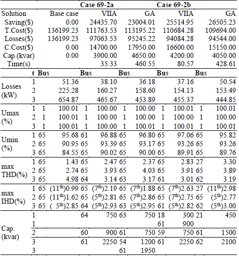
The first case analyzed (69-2a) includes the constraint of minimum voltage of 0.9 pu. The proposed solution improves the GA’s solution in 6.2% by using the 83.9% of capacitor units in the GA’s solution. The presented algorithm obtains the solution in only the 7.7% of the GA’s computation time.
In the second case (69-2b), the proposed solution is inferior in 3.7% and uses the 103.7% of capacitor units with respect the GA’s solution. The solution is obtained in the 18.8% of the GA’s computation time.
5.4 Minimum cost optimization in the circuit of 85 nodes
The circuit of 85 nodes have a total load of 2569.28 kW and 2621.19 kvar. Two different examples with harmonic distortion indices above the IEEE-519’s recommended limits are analyzed.
In the first example (1), which results shown in Table 7, the 25% of load in all nodes is nonlinear. The maximum distortion indices in peak load state THD = 6.08% and IHD = 3.6% are the 121.6% and the 119.8% respect to their respective limits in the standard IEEE-519.
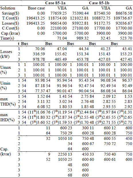
The solution proposed for the voltage-constrained case (85-1a) improves the GA’s solution in 3% and uses only the 81.5% of the total capacitor units in GA’s solution. The presented algorithm obtains the solution in only the 7.2% of the GA’s computation time.
In the second case (85-1b), the proposed solution is superior in 1% respect the GA’s solution, uses the same amount of capacitors’ units and is obtained in the 6.2% of the GA’s computation time.
In the second example (2), which results offered in Table 8, the 30% of load in all nodes is nonlinear. This base case presents a heavy harmonic distortion with maximum indices THD = 7.4% and IHD = 4.52%, which means the 148% and the 150.8% of the limits recommended by the IEEE-519 standard.
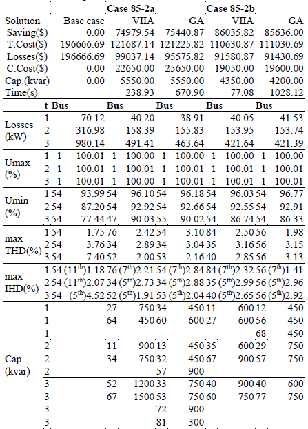
The first case (85-2a) includes the constraint of minimum voltage of 0.9 pu. The proposed solution reaches the 99.4% of saving of the GA’s solution by using the same amount of capacitor units. The presented method employs the 35.6% of the GA’s computation time.
In the second case (85-2b), the proposed solution increases in 0.47% the saving of the GA’s solution using only the 97.2% of the capacitor units in the GA's solution. The solution is obtained in the 7.5% of the GA’s computation time.
6. Conclusion
The presented method optimizes the capacitors placement on distribution circuits contaminated by the presence of nonlinear loads.
Several load states with different magnitude and duration are considered, which allows the simultaneous determination of the number, size, placement and time-control of fixed and switched capacitors. All loads of the circuit must follow the same daily pattern of variation.
This method does not use sensitivity factors to preselect the locations to place the capacitors, instead selects a large set of candidate locations where the capacitors can be placed. That set is sufficient to allow that the search algorithm examine a great number of possible locations.
Different harmonic spectrums can be selected for representing the systems power source voltage and each of the nonlinear loads currents in the circuit.
The formulation guarantees the obtaining of feasible solutions (composed by standard units) that comply with the voltage’s power quality constraints and with the capacitors overstress constraints.
The good results obtained in the solving of the presented examples is the best proof of the effectiveness of the constraint (22) in controlling the harmonic distortion.
The experience of use of this methodology shows that even some severe distortion cases can be solved. More difficult cases that cannot be solved with this method normally requires passive filters to compensate the reactive power and mitigate harmonic problems.
Although the modifications made for consider the harmonic distortion, augment the calculating burden of the method, the variables’ inclusion and interchange algorithm is still efficient in the search of solutions.