


 English (pdf)
 Article in xml format
 Article references
 Send this article by e-mail
 Cited by SciELO
  Cited by Google
  Similars in
SciELO
Similars in
SciELO  Similars in Google
 Permalink
Nomenclature
ṁ waterEC1 = Water mass flow inlet to the air circulation chamber 1 [kg/s]
ṁ Fin = Fabric mass flow inlet to stenter machine [kg/s]
ṁ AirRTEC1 = Air mass flow inlet to circulation chamber 1 [kg/s]
W FAE = Fans and extractors power [kW]
ṁ AirLE1 = Air mass flow outlet from the extraction duct 1 [kg/s]
ṁ WaterLE1 = Water mass flow outlet from the extraction duct 1 [kg/s]
ṁ AirLE2 = Air mass flow outlet from the extraction duct 2 [kg/s]
ṁ WaterLE2 = Water mass flow outlet from the extraction duct 2 [kg/s]
ṁ WaterOC7 = Water in the fabric outlet from the air circulation chamber 7 [kg/s]
ṁ Foutlet = Fabric mass flow outlet from the stenter machine [kg/s]
ṁ AirRTEC7 = Air mass flow inlet to the circulation chamber 7 [kg/s]
ṁ OILin = Hot oil mass flow inlet to [kg/s]
ṁ OILoutlet = Hot oil mass flow outlet the heat exchangers set [kg/s]
ṁ WaterEvp = Evaporated water in the stenter machine [kg/s]
ṁ WaterERTAC1 = Water mass flow inlet to air circulation chamber 1 [kg/s]
ṁ WaterERTAC7 = Water mass flow inlet to air circulation chamber 7 [kg/s]
TFM = Total fabric meters [m]
WER= Weight of each roll [kg]
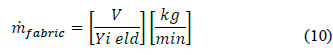
V = Fabric speed [m/min]
CP OilIN = Specific heat of hot oil (inlet) [kJ/kg°C]
T OilIN = Oil inlet temperature [°C].
CP FIN = Specific heat of fabric [kJ / kg ° C]
T FIN = Fabric inlet temperature [°C]
h WaterEC1 = Enthalpy of water inlet to the circulation chamber 1 [kJ/kg]
h AirRTEC1 = Enthalpy of air inlet to circulation chamber 1 [kJ/kg]
h AirRTEC7 = Enthalpy of air inlet to circulation chamber 7 [kJ/kg]
h WaterLC7 = Enthalpy of water outlet in the fabric in the circulation chamber 7 [kJ/kg]
CP OilO = Specific heat of hot oil (outlet) [kJ/kg°C]
T OilO = Hot oil temperature outlet [°C].
CP FO = Specific heat of the fabric (outlet) [kJ/kg°C]
T FO = Fabric outlet temperature [°C]
h AirLE1 = Air enthalpy from extractor 1 [kJ/kg]
h AirLE2 = Air enthalpy outlet from extractor 2 [kJ/kg]
h Evp = Latent heat of water [kJ/kg]
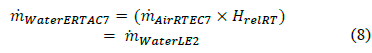
HrelRT = Relative humidity at room temperature
1. Introduction
Nowadays, the high demand for energy and the effects of climate change have motivated a search for new alternatives that improve the efficiency of industrial processes. In particular, waste heat recovery has been widely implemented to improve energy efficiency. It has been estimated that between 20% and 50% of the energy used in the industrial sector is wasted as heat in the form of hot exhaust gases, cooling water, and heat losses from the surfaces of hot equipment and heated products [1]. The textile sector presents great opportunities to increase its energy efficiency by using the waste heat from equipment that offer high energy availability, such as boilers, natural gas generators, waste water form dyeing, and stenters [1-4].
In the textile sector, stenter machines can consume up to 30% of the total thermal energy that is used, and potential energy savings in this process oscillate between 20% and 70% [5]. Heat setting, part of the finishing process applied to fabrics, aims to provide the fabric with dimensional stability by thermally fixing the fibers. In stenter machines, most power is used to evaporate water in the fabric and heat air [6]. The power consumption of this process depends on the specific operation and fuel, but it varies between 2.5-7.5 GJ/ton in the drying and 4.0-9.0 GJ/ton in the heat setting stages [6]. Nevertheless, when optimized, such consumption can be as low as 3.5-4.5 MJ/ton of processed fabric [5].
In general, to increase the energy efficiency of heat setting, heat exchangers are implemented to recover the waste energy in the gases it produces. Some of the most common types of heat recovery are recirculation, tube heat exchangers, plate heat exchangers, thermal wheels, heat pipes, run-round coils, and direct contact coolers [7]. The selection of the type of heat exchanger depends on different criteria such as effectiveness, fouling factor, cost, and payback period. Furthermore, such selection and energy recovery level also depend on the specific operation conditions of the equipment that can provide waste heat [8].
Therefore, increasing the energy efficiency in industrial processes by heat recovery is an opportunity to obtain economic and environmental benefits. In this study, we calculated the mass and energy balances in an actual heat setting process in a company in textile sector in Antioquia and determined the amount of thermal energy that could be recovered. Finally, we applied specific criteria to select one of the most commonly used heat recovery technologies for this purpose and determined the thermal energy recovery potential using such technology.
2. Methodology
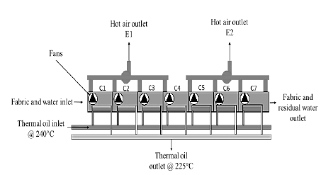
In this article, we studied a KRANZ stenter which is currently in operation. It has seven air circulation chamber and two hot gas extractor fans. The mass and energy balances were calculated only in the heated chambers because that is where the heat transfer occurs in order to dry and heat set the fabric. Fig. 1 presents a scheme of the seven heated chambers.
Source: the authors
Figure 1 General scheme of the heated chambers in the stenter, the outlet ducts of Chambers 1-4 are connected by Extractor fan 1 (E1). Likewise, the outlet ducts of Chambers 5-7 are connected by Extractor fan 2 (E2). Each chamber is heated using a heat exchanger through which hot thermal oil is circulated.
2.1 Mass and energy balance of the stenter
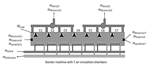
This mass and energy balance and the assumptions made here are based on previous studies [9-11]. We used the scheme in Fig. 2, which shows each one of the mass and energy inlets and outlets found in the stenter.
Hypotheses for the mass and energy balance:
There is no heat transfer between the stenter walls and the environment. This assumption is based on the fact there is glass fiber insulation (10 cm thick), and the temperature of the wall measured at 70 random points was 43±2 °C.
The heat setting process is carried out in stationary conditions.
The composition of the outlet gases of the stenter is assumed to be similar to that of air.
Regarding the sign convention, the heat transfers to the system and the work transfer are positive.
2.1.1 Mass balance
Fig. 2 presents the scheme for the mass balance of the system, which was established considering different fluids and materials: hot oil, air used to dry/heat set the fabric, water contained in the air, and fabric.
We used the following equations in the mass balance of the stenter:
Mass balance of the fabric (1):
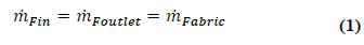
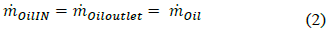
Mass balance of the oil (2):
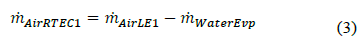
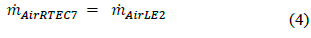
Eqs. (3)-(4) present the mass balance of air. Bearing in mind that Extractor fan 1 is connected to heated Chambers 1-4 and Extractor fan 2 is connected to Chambers 5-7, we have:
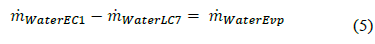
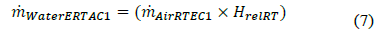
Eqs. (5)-(8) present the mass balance of water. In general, when polyester/cotton is processed, the fabric is dried in the first three heated chambers and heat set in the other four.

The parameters required for the mass and energy balance were experimentally obtained. The mass flow rate of the fabric was obtained with the mass and the time the fabric is exposed in the stenter.
The stenter was started, but the fabric was kept in place for us to measure the temperature in each area before entering the heated chambers and at the outlet of such chambers. We used a RAYTEK ST20 PRO infrared thermometer with a range between -32 and 400°C ± 1°C and an emissivity of 0.95, which is adequate to measure fabric temperatures [12].
The fabric yield, considering the weight and length of each roll of fabric, was calculated using Eq. (9).
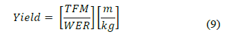
where, with the velocity of the fabric and the yield, the mass flow rate was calculated with Eq. (10).
2.1.2 Mass flow rate of air and exhaust air temperatures
The mass flow rate of the hot air that is released into the atmosphere was calculated with the volumetric flow rate and density. The volumetric flow rate was measured using a Pitot-type TESTO 485-4 differential pressure meter, which is also equipped with a Type K temperature probe with a measurement range between -60 and 400°C. Such rate was measured considering the requirements described in [13].
2.1.3 Mass flow rate of the water that enters along with air into the stenter
The moisture of the air that enters the stenter was determined using the psychrometric properties of air and using an online psychrometric calculator that enables users to make corrections for altitude [14].
2.1.4 Mass flow rate of evaporated water
To determine the mass flow rate of water, we measured the fabric moisture before and after the process by taking representative pieces of fabric and analyzing them in a Precisa XM60-HR moisture analyzer. The mass flow rate of evaporated water was calculated using the difference between the inlet and outlet fabric moisture.
2.2 Energy balance
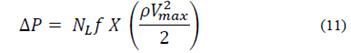
To calculate the energy balance, we took into consideration the mass flow rates of the fluids in the process and the fabric, as well as the power of the fans. Eq. (11) presents the energy balance we implemented.
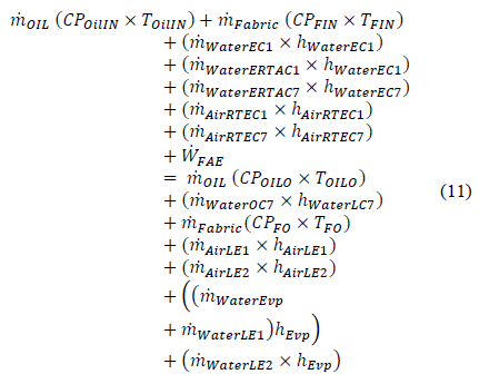
The properties of the fluids and the fabric were determined using tables of thermodynamic properties [15]. The instantaneous power of the fans was measured using a Fluke 435 power quality analyzer.
2.3 Selecting a heat exchanger to recover heat from the stenter
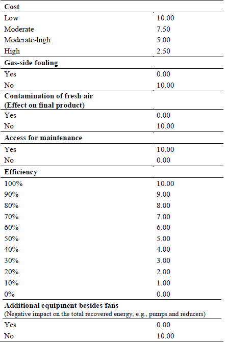
Since different types of heat exchangers can be used to recover heat in the textile industry, we defined specific selection criteria to find the best alternative (see). Such criteria, taken and adapted from [7], were assigned values that depend on the system requirements.
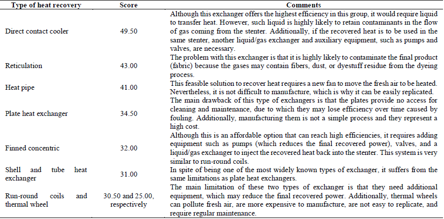
Once we applied the values of the selection criteria to each exchanger, we obtained the results in Table 2. Additionally, considering that higher values represent better options, Table 3 presents a more detailed analysis of each type of exchanger that can be used to recover waste heat from the stenter.
Table 2 Application of selection criteria to several types of heat recovery.
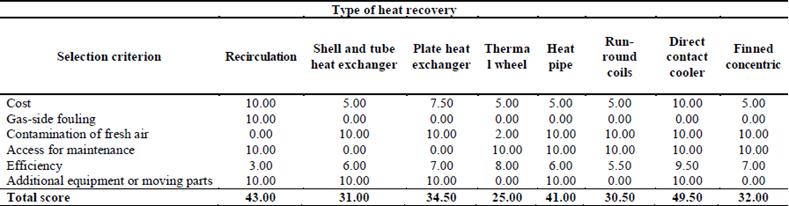
Source: authors’ elaboration
2.4 Methodology to design the heat exchanger
Based on the methodological analysis described above, heat pipes are a viable solution to recover heat in this case. The exchanger was designed using an iterative process to find the best arrangement of the thermosyphons. This process was completed following the decision-making map in Fig. 3. The equations to find the value of each variable in this map were taken from [15-19]. The constraints to define the final geometry of the exchanger included:
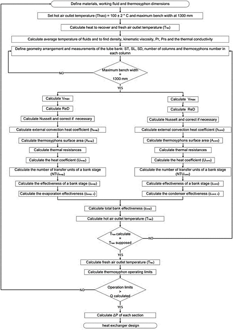
A gas outlet temperature of 100°C ± 2°C
A maximum bank width of 1300 mm (The ducts of the stenter are 750 mm. This constraint seeks to avoid abrupt transitions at the inlet, which can result in the fluid only going through the middle and not coming into contact with the thermosyphons located on the sides.)
2.4.1 Working fluid and thermosyphon material
The working fluid and the material of the thermosyphons were selected considering the temperature range of the gases and the recommendations in [20].
3. Results
3.1 Mass balance
Table 4 presents the results of applying the equations described in the methodology of the mass balance and the values of the experimental properties.
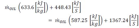
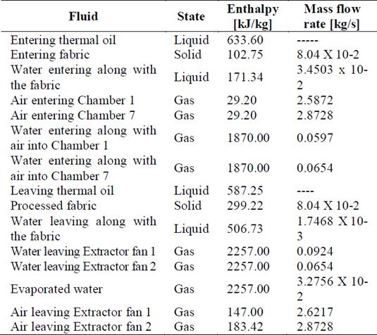
Thus, the mass flow rate of the oil is
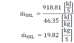
The energy flow that enters and leaves along with each fluid in the heat setting process is presented in Table 5.
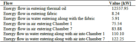
The energy balance shows that the total transferred heat is 918.75 kW, which are supplied by the thermal oil to dry and heat set the fabric, in addition to 40.01 kW of electrical energy that are transformed into work to move the air in the heated chambers and extract it from the stenter. Fig. 4 is a Sankey diagram that represents the thermal energy in this process.
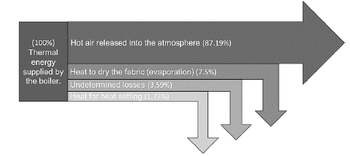
The energy that can be potentially recovered, leaving through the extractor fans of the stenter in the form of hot air, amounts to 800.97 kW, which represents 87.19% of the total energy used in the process. The heat setting process of the fabric selected in this study consumes 11.01 GJ/ton in total, which is 22.00% higher than the maximum values in the literature [5] and may be caused by the age of the equipment and its original design. However, thanks to our analysis, we identified an opportunity to reduce its energy consumption and increase the energy efficiency of the process by recovering heat from the exhaust gases of the stenter to preheat entering air.
3.2 Design of the heat exchanger
Table 6 presents the summary of the results of Heat Exchangers 1 and 2 following the methodology described in Fig. 3. (As the stenter has two extractor fans, the values were calculated for one exchanger per extractor fan.) The table shows a difference in the area of the two exchangers, which is due to the fact that Heat Exchanger 2 has more stages because the fluid enters the equipment at a higher temperature, modifying the convective heat transfer coefficient. Furthermore, thanks to the larger number of stages, its effectiveness is also higher.
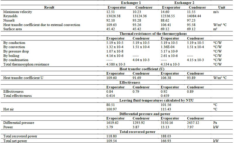
Our effectiveness results are in line with those in [21], which reported an effectiveness between 37% and 65%, and [22], in which an effectiveness between 15% and 75% was found. The following section details the configuration and working fluids of the thermosyphons.
3.2.1 Working fluid and material of thermosyphons
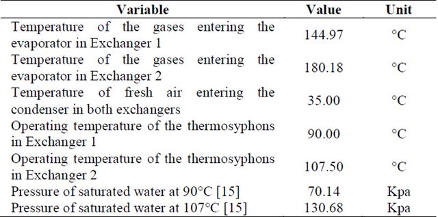
The working fluid selected for the thermosyphons was water because the outlet temperatures of the stenter gases are 144.97°C and 180.18°C.
The material of the thermosyphons was Type M copper, which is a kind of economical commercially available tubing in Colombia, where it is mainly used for hot water installations. Furthermore, copper offers high thermal conductivity and is compatible with water.
3.2.2 Operating temperature and pressure of the thermosyphons
Table 7 presents the calculated operating temperature and corresponding pressure for saturated water of the thermosyphons in Exchangers 1 and 2.
To ensure the copper tubing would endure the operating pressures, its minimum thickness was
These two minimum thicknesses are below that of the copper tubing selected in this study (i.e., 0.889 mm), which can therefore be used ensuring an appropriate operation and minimizing the thermosyphons’ risk of breaking.
3.2.3 Casing material
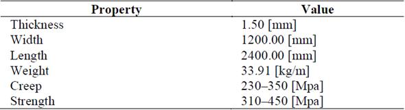
Since the exhaust gases of the stenter contain water vapor, we selected galvanized steel for the casing material. The properties of the latter are presented in Table 8.
3.2.4 Insulation material
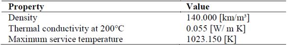
The heat exchangers were covered with thermal insulation blankets made of mineral wool, whose properties are detailed in Table 9. The conductivity of this material is low, which is why it is considered adequate for heat exchanger insulation.
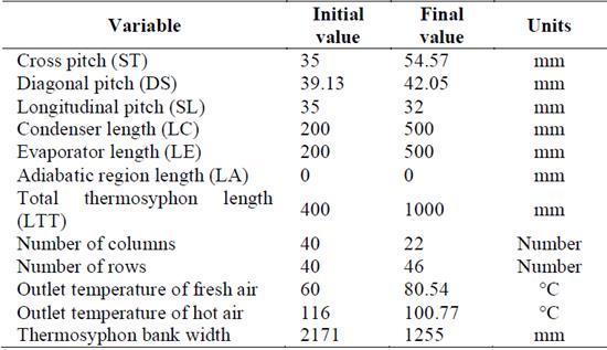
3.2.5 Geometric arrangement of the tube bank of the thermosyphons in Exchanger 1
The thermosyphons were placed in a triangular (rotated) staggered configuration with both flows crossing the thermosyphons. Such geometric array was selected so that the (hot or fresh) air comes into contact with the thermosyphons in its way in the second row, thus avoiding possible outlet ways without maximum contact with the thermosyphons.
Table 10 details the initial values that were randomly assumed and the final values after the iterative process was completed following the decision-making map.
3.2.6 Equivalent thermal conductivity of a thermosyphon
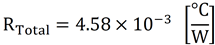
Finally, the total thermal resistance and conductivity of a thermosyphon are, respectively,
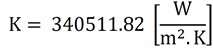
This conductivity, a result of the total thermal resistance that was found, is 851 higher than that of copper (average copper conductivity: 400 W/m²°C). Zohuri (2016) described a thermosyphon, with water as working fluid, that has an effective thermal conductivity in the order of 1x10⁵ W/m²°C; in addition, depending on design and operating conditions, it is common to find values around 4x10⁵, which is 1000 times higher than that of copper. Other studies [20,23,24] support this result and associate it with high heat transfer coefficients in boiling and condensation processes.
3.2.7 Operating limits of the thermosiphon
Table 11 presents the operating limits obtained for the thermosyphon designed here. The volume of liquid used to calculate the dry-out limit was 50% of the evaporator, which is a volume of 0.000140679 m3 of water. Considering that Exchanger 1 is composed of 1012 thermosyphons, which are subjected to a heat flow of 118802 W, and if each thermosyphon transfers the same amount of energy, as a result, we have that each thermosyphon will be subjected to a maximum heat flow of 117.4 W. This value is significantly lower than those found for each one of the operating limits, which indicates that the design proposed here is adequate.
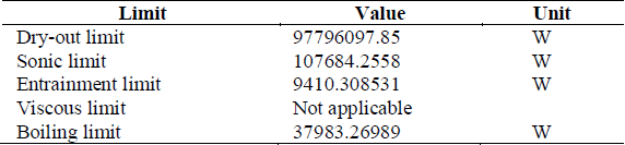
It can be concluded that the thermosyphons operate without a problem because the maximum heat flow is never above any of their operating limits.
3.2.8 Mechanical design
The parameters to calculate the differential pressure are presented in Table 12:
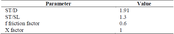
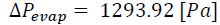
The differential pressures for the evaporation and condensation sections are

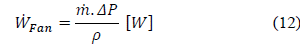
The power needed to move the hot and fresh air through Exchanger 1 is
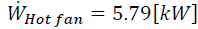
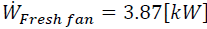
This additional power needed to install the heat exchange system represents 8.16% of the total power recovered with Exchanger 1 and 11.2% of that with Exchanger 2. These values are low considering the global size of the equipment.
4. Conclusions
We found that, in the process of fabric drying and heat setting in a stenter, the main heat transfer occurs in the heated chambers. The mass and energy balances showed that the thermal consumption of the stenter amounted to 918.65 kW, 95.82% of which are supplied as thermal energy by the hot thermal oil and 4.18% as electricity. Out of the total thermal energy, 800.97 kW are available in the hot air used in the process.
The heat setting process of the stenter analyzed in this study consumes 11.01 GJ/ton in total, which is 22% higher than the maximum values in the literature and may represent an opportunity for improving its energy efficiency. Finally, using this heat recovery system with thermosyphons, the thermal energy consumption of the stenter can be reduced by 30.1%.

