


 Inglês (pdf)
 Artigo em XML
 Referências do artigo
 Enviar este artigo por email
 Citado por SciELO
  Citado por Google
  Similares em
SciELO
Similares em
SciELO  Similares em Google
 Permalink
1. Introduction
The aeronautical industry has experienced continuous growth since the first years of its inception. For instance, one of the most notable aeronautical operators in the industry has increased its fleet acquisition by up to 120% in the last 20 years. [1] This behavior reflects the evolution and improvement in many aircraft components. The manufacturers have focused on optimizing the cost/benefit ratio of the operations. An example of cost/benefit optimization was the rapid reduction of engine fuel consumption, which has decreased from an average of 8 liters per passenger per 100 km/h in 1985 to 3 liters in 2017. [2]
Likewise, aircraft maintenance is necessary to maintain airworthiness, by means of techniques and tools that enhance repair processes such as test benches and ground support equipment. Advances made in aeronautical systems, subsystems, and components facilitate maintenance processes carried out within the aeronautical Maintenance, Repair and Overhaul (MRO) stations, which perform maintenance of the systems, subsystems, and components for aeronautical use, including engines and propellers.
The MRO stations have several advanced tools for handling the different components. However, in the case of engines, many stations have only basic ground support equipment that does not enable good handling to obtain optimum performance, and instead make engine maintenance an uncomfortable and painstaking process.
In order to obtain optimal results in time and maintenance costs, it is necessary to optimize the procedures and operations performed by technicians, to enable greater frequency and shorter duration of maintenance. In this context, this study focuses on addressing the difficulties of rotating and handling Turboshaft engines during the maintenance process at an MRO station in Colombia, which mainly arise due to the large size, and especially the weight of the engines, which ranges between 200 and 450 kg. These maneuverability difficulties during the engine's maintenance cause delays and long waiting times for the aircraft operators, and any improvement in this regard would be of interest for all parties involved. [4,5]
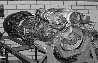
The first Turboshaft engines were adaptations of the Turboprop engines, supplying energy to the propeller through an axis directly driven by the gas generator, through a reduction box. Unlike the Turboprop, the Turboshaft uses the residual jet thrust to add air to the turbine, or by rotating the exhaust by 180 degrees to produce two opposite jets, as shown in Fig 1.
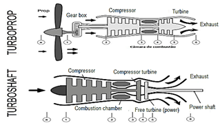
Fig 2 shows the evolution of the different models of Turboshaft engines in terms of their weight/power ratio.

The weight/power or mass/power ratio is a simple, clear and widely used qualitative indicator to compare engine performance.
The first engines were large and consequently heavy, thus restricting the aircraft's range of flight. However, there was a progressive increase in the mass/power ratio between 1947 and 2014, which suggests increased awareness in the industry of the need to reduce the engines’ weight in order to obtain better performance. For this reason, the focus has shifted to making new engines lighter and with higher performance.
As for the evolution of the Turboshaft engines' sizes, Fig 3 shows their average length and diameter. The graph indicates that substantial progress has been made in the reduction of the engine’s dimensions to an average length of 1660 mm and average diameter of 630 mm. This was possible thanks to the implementation of composite materials and the incorporation of electronic technologies.
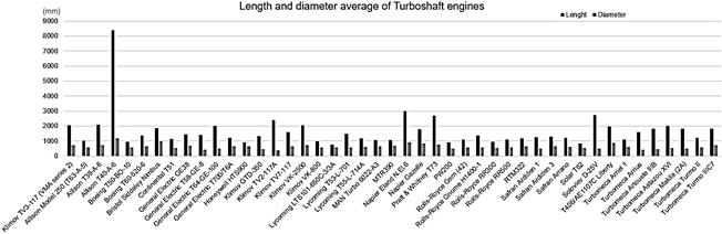
Source: Bejarano, 2019. [7]
Figure 3 Average Length and diameter of Turboshaft engines by year of manufacture.
The most frequent use of this type of engine is in the civil aviation industry. The development of methods and technologies to reduce design, manufacturing, and maintenance costs represents a major factor. Some of the approaches proposed by current research are the improvements in compressors, having less interstitial air losses, and reducing the weight, as shown above.
The main purpose of this study is to carry out the conceptual design of ground support equipment dedicated to Klimov TV3-117 engines, aimed at simplifying maintenance operations, for its potential implementation at aeronautical MRO stations. A prototype of an engine handling device will be developed using the CATIA design software, meeting the established technical and design requirements. Structural analysis of the projected prototype will be performed by means of static simulation in the Solidworks structures module to determine the technical and structural feasibility of the engine handling device and to establish its potential scope and limitations [8].
Computational modeling was performed on the prototype developed using Computer-Aided Design, and applied research was also carried out for the structural analysis of the designed ground support equipment for engine handling and rotation.
1.1 Klimov TV3-117 Engines
Turboshaft engines are a type of gas turbine that produces shaft power rather than a jet thrust. They consist of two main sets of parts: the turbine section driven by the primary shaft (compressor, combustion chamber, and one or more stages of the turbine) and the power section driven by the secondary shaft (additional stages of turbine, one gear reduction system, and the output shaft). In essence, the first section raises the temperature of the expanding gas and triggers the second [9].
Among the types of Turboshaft engines, this study will focus on are those belonging to the Klimov TV3-117 family. Designed by the Russian Aeronautical Manufacturer Klimov, this engine was developed in 1972 for helicopters and airplanes. According to Lom Praha, one of the leading companies providing MRO services to helicopters, the Turboshaft TV3-117 engines in all their versions belong to the most widely used propulsion units worldwide. Since its creation, more than 25,000 units have been built, and it is still being manufactured today. This Turboshaft engine is used, among others, in the Mil Mi-8, which is, in turn, the most-produced helicopter in the world [10, 11].
1.1.1 Specifications (TV3-117VM)
The propulsion unit of Mi-8 helicopters is composed of two TV3-117VM engines and other additional auxiliary systems. The engine control is carried out employing a unified control system that allows maintaining the required revolutions per minute (RPM) in the main rotor, both manually and automatically [9].
1.2 Aircraft engine attachment system
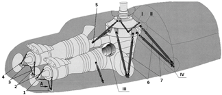
The TV3-117VM engines are mounted on the fuselage roof panel so that their axes and the helicopter's longitudinal reference line form a 4 ° 30' angle. Each engine is fixed to the fuselage using two support systems: the front and the spherical rear. The frontal system is made up of two long and two short vertical bars. It is used to prevent engine movements in the vertical and transverse directions and prevents the engine's rotation in relation to its axis. The spherical rear system prevents the engine from moving and allows rotary movement with respect to all axes. With this clamping mode, axial forces are supported only by the back support and by the short and long columns.
The other forces are transmitted to the front vertical bars and the back support, proportionally to the distance from the engine's center of gravity. The engine's alignment with the main transmission is carried out in the assembly process, varying the vertical bars' length, rotating the tensioners without removing the vertical bars from the engine or the roof supports. (Fig 4).
Source: KAN, 2009. [12]
Figure 4 Positioning of the TV3-117VM engines on the aircraft. Scale 1:68.5.
1.3 Rear ball attachment
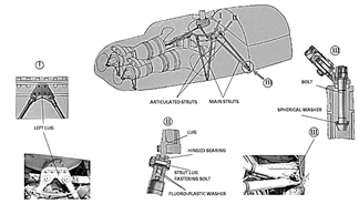
The engine is connected to the main transmission through the ball bushing attached to the screws on the main transmission body. The engine body is attached to this bushing by means of a spherical cover. To remove the engine from the main transmission, which has an additional bracket, a special device was installed in the fuselage's central section (Fig 5).
Source: KAN, 2009. [12]
Figure 5 Rear mounting of the TV3-117VM engine. (1) - Brackets, (2) - External rods of front fixture, (3) - Internal rods of front fixture, (4) - Link, (5) - Spherical support of rear fixture, (6) - Coupling struts, (7) - Main struts, (I) - Lug, (II) - Strut attachment, (III) - Rear attachment, (IV) - Spherical washer (I). Scale 1:68.5.
For the engine’s correct installation, it is necessary to adjust its longitudinal axis and align it with the main transmission.
2. Methodology
An applied research approach was used for this study. As stated by Vargas, it is based on identifying the specific needs of a sector, whether social or productive, that can be converted into solutions. For the case of this study, an innovative solution was proposed for a need that was found at MRO (Maintenance, Repair, and Overhaul, in accordance with Colombian Aeronautics Regulations RAC 4.11, RAC 43, RAC 145, based on the Federal Aviation Regulations FAR 43, FAR 145 and Latin American Regulations LAR 43, LAR 145) facilities, such as a Helicopter Maintenance and Repair Center. At this MRO station, a problem was found regarding the maintenance of helicopter Turboshaft engines. With the ground support systems current in place, it is difficult for technicians to carry out the process, and it is expensive in terms of uptime. Therefore, the need to obtain a product capable of improving these types of processes and, at the same time, improving the quality of life and the work conditions of the people involved was evident [13].
Consequently, rather than emphasizing general theoretical aspects, this study focuses on a specific application aimed at making changes in the studied reality by combining research and practice based on knowledge acquired in the field of engineering through designing a product in a conceptual stage for the aeronautical industry.
The different steps to be followed in this project are as follows: first, the requirements to be met by design are defined; then an analysis is made of the engines to which this product could be applied and their evolution in the last 50 years, concerning dimensions, weight, and power; afterward, the engine handling device was designed as a tool for maintenance meeting the basic requirements, and based on them, the process consisted of transforming the information on the detailed conditions, needs and requirements into a projection in the computer-aided design software, and finally to simulate the structural validation tests.
3. Needs and requirements of the GSE
The first step in creating the ground support equipment for the Turboshaft Klimov TV3-117 engines is to know the basic needs and requirements of the project and their dimensions, weight, and anchoring points necessary to safely handle the engine.
3.1. Needs
Need 1: As can be seen in Fig 6, the Klimov TV3-117 engine is subject to a fixed support structure, which creates limitations in terms of freedom of movement. Consequently, a fundamental part of our design will be to increase such freedom of movement.
Need 2: It is necessary to reduce the time and costs associated with the Turboshaft engines' maintenance process.
Need 3: Design the ground support equipment for a Klimov TV3-117 engine that is structurally strong and able to withstand the static weight of an engine, as well as its assembly and disassembly cycles.
3.2. Ground support equipment requirements
RE.1: The ground support equipment must prevent structural failure; consequently, the loads that the structure must be able to withstand during operation are substantially greater than the static load.
RE.2: The ground support equipment must be able to withstand weight of at least 440 (kg) to meet a safety factor of 1.5, since the TV3-117 VM engine weighs 293 (kg).
RE.3: The ground support equipment must be able to accommodate as a minimum an engine with height of 728 (mm), length of 2055 (mm), and width of 650 (mm).
RE.4: The ground support equipment must have at least three guidewires with their respective anchoring points.
RE.5: The ground support equipment must be manufactured with light and resistant materials for heavy duty use, and must not produce corrosion or wear or in any way affect any component that is in contact with the engine.
4. Design and materials
One of the most critical factors for obtaining optimal design results is to carry out an appropriate material selection process. This enables creating a product that is efficient and, at the same time, profitable for its manufacture.
4.1. Types of materials in the design
The material chosen for manufacturing the parts is ASTM A36 steel. It is the most widely used structural steel, as it combines a low price with reasonable strength values for such use. It is low-alloy carbon steel. This material is resistant and widely used to manufacture aviation workbenches. Stress, load, fatigue, bending and resistance simulation tests were performed on the bench designed with this material, based on the mass of the engine, lifting distance and rotation of the engine. The material was additionally chosen for its ductility and malleability properties. The American International Standardization (ASTM) establishes the minimum acceptable values for the properties for plates, bars, and profiles of this material with a thickness of less than 203 mm, as shown in Table 1.
Table 1 Minimum values for the properties of A36 steel established by the ASTM standard.
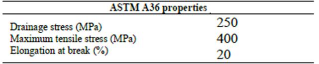
Source: MatWeb, 2019.
Besides, ASTM A36 steel is supplied in various formats that cover all the prototype’s needs [15].
4.2. Modeling
Through computational modeling, the prototype project was carried out on a 1:12 scale.
The engine will be held in suspended position by means of a swing clamping ring (Fig. 7), thereby leaving the surface of the engine exposed for maintenance.

The swing clamping ring will be hung from lifting hooks by means of two steel cables, and the engine will be affixed to the clamping ring by means of four fixing brackets that will hold the engine. (Fig. 8)

5. Simulation conditions
The study focused on the sections that are most critical for structural safety. The structural analysis was done in Solidworks 2017 in order to validate the project from the initial stage.
Static simulation tests were run to understand how the design will behave, with results as close as possible to reality, considering the following parameters: Material, Boundary conditions, Mesh size, all carried out on a 1:1 Scale.
A safety factor of 1.5 was established as the minimum acceptable level for the design limit, based on the Von Mises factor of safety criterion, which is calculated by the software package.
5.1. Rotating handle simulation
Based on the prototype design, the material’s properties and volumes (Table 2) and the load and fastening elements (Table 3) are determined.

5.2 Loads and fasteners
The fixing elements, in the case of the swing clamping ring, have the function of providing the necessary space to anchor and position the screw. (Fig. 9).

The load properties of the fasteners are described in Table 3.
5.2.1. Rotating handle mesh
A Triangulation-type mesh was implemented for the handle, as shown in Fig. 10, with an anti-aliasing mesh, which provides improved resources to model object shapes in a more detailed way.
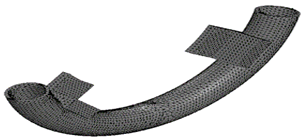
The properties considered for the prototype are shown in Table 4.

5.2.2. Analysis of the rotating handle simulation
The structural analysis of the pieces, considered of great importance for the project, was carried out through Solidworks. For the effects of assessing the safety factor, the model indicates that the piece is safe only if all the segments are in blue (darker tone) or 6.478e+3 N/m2 (Fig. 11), taking into account that the darker color is interpreted as indicating that minimum deformation occurred, whereas a red band indicates a high level of deformation that tends to break the material.
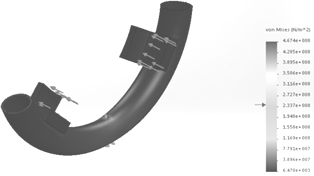
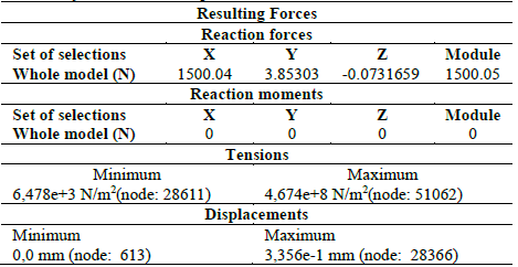
5.2.3. Static analysis of stresses and displacements of the rotating handle
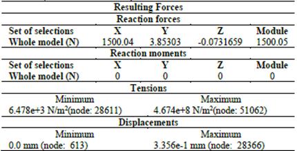
Fig. 12 presents the results obtained in Solidworks to analyze stresses and displacements, which show an excellent dispersion of forces, making the part efficient in structural terms.
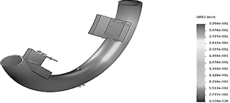
Table 5 shows the results found in Solidworks for displacement and stress analysis.
5.2.4. Fixing bracket simulation
The fixing bracket (Fig. 13) is one of the most critical parts, as it is the non-contact intermediate between an engine and the swing clamping ring.
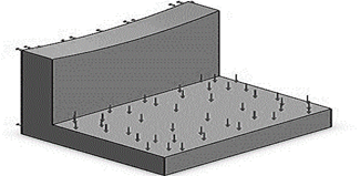
Besides, the fixing bracket absorbs the movements of the ring with fixing properties (Table 6), the maneuverer gain, or the engine hanger's weight. This part is ready in the position of resistance and obtaining optimum results in terms of use.


5.3 Static analysis of stresses, displacements, and deformations.
As it is presented in Table 8, the result of a stress analysis carried out to the fixing bracket shows that the maximum strength before accepting rupture is 1.460e + 7 N/m2.
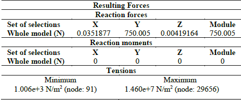
As show in Fig. 15, the fixing bracket provides excellent dispersion of stress loads throughout the rest of the part.
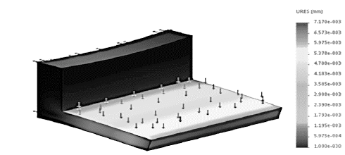
5.4 Static analysis of displacement and deformations of the fixing bracket
In the Fig 16 it is shown the results of the displacement analysis, it can be seen that it does not represent a significant effort for the fixing bracket.

Considering information from Table 9, the structural viability of the part can be established.
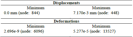
In the figure of the results of the deformation analysis (Fig. 17), it can be seen that it does not represent a significant effort for the fixing bracket.
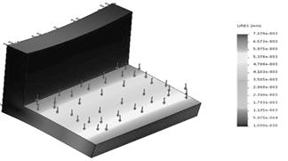
Considering information from Table 10, the structural viability of the part can be established.

5.5 Loading screw simulation
The loading screw is a crucial anchor piece to structure the swing support. The loads are applied as shown in Fig. 18.
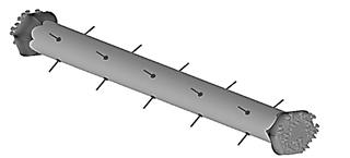
The loading screw was designed with cast steel, as shown in Table 11.
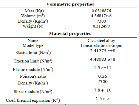
5.5.1 Loads and fasteners
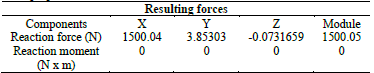
The normal force of 1N is applied to the screws, the resulting forces are shown in Table 12.
The mesh properties are shown in Table 13 and they are the same as the previous pieces.

5.5.2 Static analysis of stresses, displacements, and deformations.
In Fig. 19a, 19b and 19c stresses and displacements in the loading screw are sampled and analyzed.
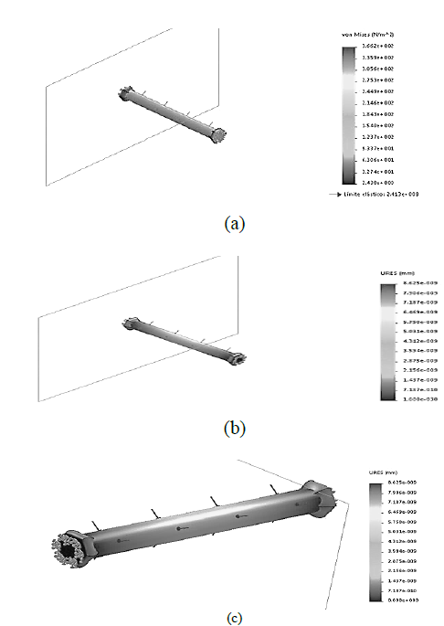
Source: Prepared by the author
Figure 19. (a) - Static analysis of the load screw - stresses. (b) Static analysis of the load-displacement screw. (c) Static analysis of the load screw - deformations.
In Table 14, it is possible to observe a concentration of forces at the ends of the screw, but the design achieves a good dispersion of loads.
6. Discussion
6.1. Technical and structural feasibility of the engine handling device
This study aims to reduce engine downtime and, consequently, reduce the cost of processes. Computer simulations using computer-aided design (CAD) software, and a structural analysis of the ground support equipment for handling and rotating turbocharger engines were performed. The selected loads were simulated using the Solidworks software. For this, it is necessary to follow an interface, which consists of assigning the corresponding material and blocking elements, as well as the connections that must be performed in the model.
The next step is to proceed to the analysis and obtain the results that evaluate the model's efficiency and conformity with the established requirements, examined by means of the transformation and displacement analysis. It was found that the prototype is efficient and resistant to stresses applied (average engine weight); as shown in the simulations of the rotation handle, fixing bracket and load screw.
The way of lifting these engines should also be defined, and their suspension and handling in this position suggested by the workbench, in addition to meeting all the technical and design requirements established in section 3. Needs and Requirements of the GSE, the engine handling device does not interfere with the ducts' fluids and will not have adverse effects on that part. Finally, a conceptual prototype of the support was developed in the design stage, meeting the requirements, which can withstand the loads and offer a safety factor greater than 1.5 for the TV3-117 VM engine, which weighs 293 kg.
7. Conclusions
The contribution of this research is focused on the aeronautical MRO stations that perform maintenance processes on Klimov TV3-117 engines. Normally seven workers are required for this process to constantly move and manipulate the engine when carrying out a repair job, which takes about 13 days, 8 hours per day, for a total of 728 man-hours. With the proposed handling device, the work can be carried out by just 5 workers, for a total of 520 man-hours. Thus, around 208 man-hours would be saved for servicing each unit, since instead of requiring five specialized technicians and two inspectors, the necessary personnel would be reduced by at least one specialist and one inspector for this same process. In this way, a time reduction of up to 28.5% is estimated compared to conventional ground support equipment.
The main objective was to reduce the time of preventive, predictive, and corrective maintenance of the Turboshaft engines, employing this ground support equipment for engine handling. The complexity of the handling processes is minimized by providing a suspended vertical clamping ring that offers greater freedom of movement. Operators and technicians have a more comfortable and efficient way to carry out their work, continue inspections, arrangements, component changes, parts, and so forth. An aspect that requires refining is to ensure that the lifting of these engines and their suspension and handling in this position does not interfere with the ducts' fluids and will not have adverse effects on these sections.
One of the project's limitations is that although its structural viability is optimal for the vast majority of Turboshaft engines, the design was developed exclusively for the requirements, specifications and dimensions of the Klimov engine; consequently, the prototype must be resized for different applications.
It was concluded that the conceptual project's structural feasibility is exceptional because the test results on some of the parts were results obtained from stresses, deformations, and displacements of blue color, which represents high safety factors and demonstrates high reliability in the parts.

