


 Inglés (pdf)
 Articulo en XML
 Referencias del artículo
 Enviar articulo por email
 Citado por SciELO
  Citado por Google
  Similares en
SciELO
Similares en
SciELO  Similares en Google
 Permalink
1. Introduction
Traditional seismic building design implies that if a major earthquake occurs the affected structure will undergo inelastic behavior which has the purpose of dissipating the energy introduced into the structure during movement. This fact implies that the building will suffer damage in its structural and non-structural elements, where the level of damage can depend on many factors. Additionally, inadequate designs can lead the structure to failure. During the Eje Cafetero Earthquake in Colombia a total of 37000 residential units were destroyed and 43000 units suffered severe damage [1]. Some of these structures were important buildings such as hospitals or educational centers. In order to design a conventional structure (for example a concrete reinforced framed building) to have an elastic behavior for earthquake design purposes ends up being economically unfeasible in most cases.
Currently, the use of special response control devices has gained more attention. Known as seismic protection systems (SPS), these are used in order to improve seismic performance in building as an alternative to strengthen their structural elements. Most of the real applications in the world use passive-type devices. These devices do not require energy in order to function and do not use the earthquake data signal information. Some examples of such devices are the buckling restrained braces [2], viscous dampers [3], tuned mass dampers [4], metallic yielding damper [5] and seismic isolation [6]. Buildings equipped with SPS have displayed a good performance during recent earthquakes. For example, the 52-story Titanium tower equipped with a set of friction dampers demonstrated a good behavior during the 2010 Chilean Earthquake, affecting only a local cladding part on an upper story [7]. International codes rule the design of building with passive energy dissipation systems, including the experimental tests needed to demonstrate the properties of dampers, such as ASCE 7- 16 chapter 18 [8].
The main differences between diverse SPS are their functioning principle. Metallic yielding dampers generally consist of small steel devices connected to the structure by braces, which dissipate energy through plastic deformations in stable hysteretic cycles when the structure is affected by an earthquake. These dampers work as a fuse, which means that after their activation during a major earthquake these must be replaced with another similar device. This replacement does not entail significant costs given that its manufacturing is economical when compared with other devices. Designing a building with these devices requires a full knowledge of hysteretic behavior in dampers as well as their precise number and location in the structure. There are different types of metallic yielding dampers, among them are the triangle added damping and stiffness [9], u-shape damper [10], rhombic steel damper [11], circular hollow damper [12], and slit steel plate (SSP) damper. Developing countries prone to earthquakes could be interested in this type of seismic protection given its low cost. Aguiar [13] reported the use of Shear Link Bosso SLB40-3 Dampers, in order to seismically retrofit an irregular educational building in Ecuador. Colunga [14] reported about seismic retrofitting with ADAS devices in a Hospital built with reinforced concrete frames in the 70s decade. In Chile, a set of high-rise concrete reinforced building was reinforced with TADAS devices shear walls and coupling beams [15]. From an experimental standpoint, it is necessary to damage prototypes in order to determine their mechanical properties. This aspect has to be considered in the project.
Specifically, SSP damper consist in small thin plates made of steel that have perforations inside. Perforations can vary in size, shape and quantity. Two plates with the same quantity of material do not necessarily display the same energy dissipation capacity as the plate’s shape affects the stress distribution through it [16]. In this regard, the following question is valuable: What is the best shape for a plate (including the shape and the number of its slits) that maximize energy dissipation capacity considering the amount of material available? The answer to these questions plays a very important role in the use of SSP for seismic protection. This is because the seismic response of the structure during an earthquake is dependent on energy dissipation capacity of the SSP damper and its distribution throughout the structure. It is possible to apply optimization concepts in order to obtain the shape of the SSP that maximizes energy dissipation capacity, as shown in [17]. On the other hand, Oviedo et al [18] proposes a methodology that can be used to equip buildings with SSP, defining quantity, properties and location of devices.
Different papers that quantify the energy dissipation capacity of SSP dampers or that assess the response in structures that use them exist. Pimiento et al [19] made a comparison of the seismic response of a lab steel frame equipped with two SSP dampers, finding that the use of plates with circle slits produced higher reductions in the frame displacements. Chan and Albermani [20] showed that the hysteretic cycles of SSP dampers with horizontal slits are stable and that as the plate is more rigid, failure occurs earlier. Teruna et al [21] carried out an experimental study on honeycomb dampers, observing that the Baushinger effect is responsible for more than 80% of the plastic energy dissipated.
This paper presents a report with numerical examples for characterizing seismic performance of perforated Steel plates. A total of 12 different geometric configurations for plates were analyzed. The quantity of material was the same in all cases. Abaqus software was used to carry out an elasto-plastic analysis of the plate subject to shear inverse loads. Finally, the level of reduction in the displacement of a two-story steel frame subjected to three different earthquakes was registered. This is an extended and improved version of the paper presented in the VIII Colombian Conference on Earthquake Engineering in 2017 [22].
2. Slit Steel Plate (SSP) dampers
A typical SSP damper is comprised of a thin plate made of ductile steel with low yielding steel, such as A-36. This allows for the damper to sustain a defined number of load cycles during an earthquake in function of the steel type used. Thickness throughout the plate is uniform. Plates present slits that aim to redistribute their stress in order for the most quantity of materials yields. The most common slit shapes are vertical, horizontal, circles, rectangles and rhombuses. Fig. 1 presents a SSP damper with vertical slits, which will present high stress concentrations in zones like slit corners [23]. The transversal plates are used to connect the damper to the structure using bolts. Given that dampers are comprised merely of steel plates and simple shaped slits, their manufacturing process is relatively easy. Additionally, SPP dampers can be manufactured by cutting sections of commercially available structural elements, like H or I shaped steel beams, such as presented in [24]
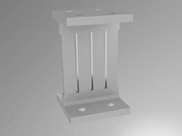
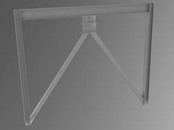
Fig. 2 shows how the dampers look like when they are installed on a steel frame. The transversal plate on the top of the SSP damper is connected to the upper beam, while the lower part is connected to braces configured in a Chevron style. It is important to guarantee that braces support the device correctly avoiding flexure of the bottom side, which will modify the expected structural behavior. Thickness is present transversal to the plate in order to ease the yielding process. The braces are connected to the column-beam joint in the lower story, its function is to transmit axial load to the joint and to contribute in the stiffness of the structure.
The SSP damper only works after inelastic deformations appear due to the differences in displacement between its top and bottom sides, as seen in Fig. 3. This displacement is the result of the relative movement between the two stories where the device is located. As the earthquake occurs the plate starts to yield dissipating energy, this ability is in function of how the plates were configured, causing the effect that at its maximum dissipation capacity, some areas of the plates do not yield during the seismic event. Therefore, optimal behavior implies that the entire plate has the possibility to yield during a major earthquake, increasing its dissipation capacity. In that sense the presence of large deformations and failure criteria have to be considered during numerical modelling in order to adequately represent the behavior of the SSP damper.

The design process of this system is similar to that of other displacement-based energy dissipations systems. Thus, design guidelines for buildings equipped with SSP dampers are defined for the international normative, such as ASCE 7-16 [8]. This code allows for seismic energy dissipation systems to take only part of the seismic force so that that a main structural system can withhold. These also define how to consider the variation on mechanical properties of devices in the structural analysis. However, an important issue is how to distribute the element throughout the building in order to generate a correct activation mechanism for both main structural elements and the SSP dampers. The way how device properties work, their quantity and their location are determined depending on the experience of a structural engineer, aided by iterative or optimization-based methodologies, such as [18] and [25], respectively.
In spite of this there are few cases of SSP dampers in real buildings. They have an enormous potential to be implemented successfully if a more comprehensive study on the subject would exist. There is no complete research that involves the numerical and experimental assessment of energy dissipation capacity in these devices. However, for a further reference, Javanmardi et al. [26] presents a state of the art on testing, development and implementation of yielding hysteretic metallic dampers. In conclusion, it is important to mention that, to the best knowledge of the authors, Colombia does not have buildings that use such technology for seismic protection.
3. Assessing the hysteresis for plates PSP dampers by finite element analysis
The implementation of new SSP dampers requires a finite element model to be used in the understanding of damper performance and design. An updating process is required to match experimental and analytical results in order to obtain a better model for the plate studied. Assessment of Energy Dissipation Capacity (EDC) is carried out on the isolated plate as well as the estimation of energy dissipated during a cyclic load. This measurement factor is used in order to determine the effectiveness of a specific device.
Some important aspects have to be considered in the modelling process. These include the definition of the constitutive model and the occurrence of large deformations. A conclusion observed by Hossain [28] states that it is necessary to include a kinematic hardening condition in the material’s behavior. Karavalisis et al [29] states that it could be necessary to have a mix of kinematic and isotropic hardening, while for the plates tested by Chen [20] the results for the first load cycle were reviewed by using only isotropic hardening. Also, it is important to consider the possible degradation of the hysteretic behavior in low-cycle fatigue. The modelling can be carried out in either two or three dimensions for individual plates. It is important to mention that if the plate is very slender there is certain probability of presenting buckling during the cyclic movement. Additionally, 2D approach generally does not consider modelling the connections attaching to the beam. Residual stresses can be elevated in the contact zone between the bolts and the plate [29]. The cyclic load is simulated by considering that there is a displacement in the top of the plate while the bottom is considered to be fully restrained. Failure criteria are stablished in order to define standards used to consider if the plate does not work.
The following section shows the procedure used to assess the hysteretic behavior of SSP dampers (as defined in section 2) using a finite element analysis in Abaqus, considering the experimental procedure carried out in [20]. The steps used are:
a. Generate the damper’s geometry, which could be imported from a CAD software. Plate dimensions correspond to the design established for the frame where the plate will be located.
b. Define characteristics of the material to be used in the plate, including the elastic and plastic information. Each type of material can present its own characteristics.
c. Select the SR4 element to model the plane stress behavior in the plate. It is considered that when the analysis is limited to the plate’s plane, this implies that no buckling is being considered.
d. Input plate thickness. The entire plate presents a single value for these parameters; thus, it is considered that stresses are uniform throughout its thickness.
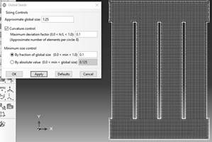
e. Assign the mesh to the plate, see Fig. 4. The software can automatically define the distribution and size of the elements. The size of the mesh used could affect the results in the estimation of EDC.
f. Define assembly for analysis. This procedure is an additional step as there is only one part in the model.
g. Create step analysis. A dynamic analysis is carried out from the results of a previous static analysis.
h. In order to define the results to be read: displacements, failures, Von Mises stresses and plastic energy dissipation.
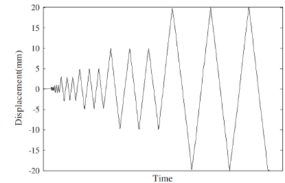
i. In order to input the displacements cycle, this displacement would have to be uniform on the top of the plate. Fig. 5 presents an example of a traditional protocol of cyclic displacements reported in [27].
j. Define the boundary condition. The bottom side is restricted to movement, while the top is only restricted in vertical direction. Fig. 6 presents a representation for the boundary conditions on the bottom side of the plate.
k. Run analysis.

4. Characteristics of the analyzed PRPs and the steel frames
This paper presents the numerical assessment of the energy dissipation capacity of SSP dampers with different slot configurations (See Fig. 7) under cyclic load. The different slit shapes (vertical rectangular, horizontal rectangles, diagonal rectangles, squares, triangles, cross-shape rectangles, rhombic-shape rectangles and circles) were selected for being common shapes that could be easily manufactured. Also, shapes M8 to M12 were proposed in order to study the dependence of the EDC on the number and distribution of the circle slits.
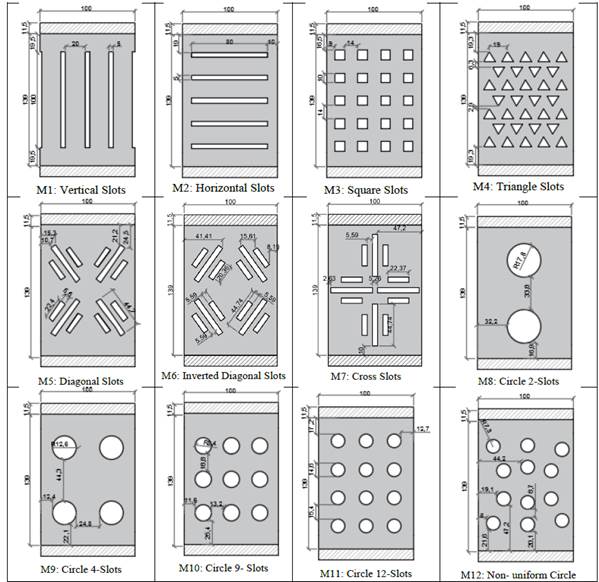
The device analyzed in reference [16] is used to define the dimensions for all setups used. The same quantity of material was used in all cases. The aim is to understand the hysteretic behavior of these devices and how their slit shape affects their respective energy dissipation capacity performance. The thickness for all plates is 8 mm. The effect is analyzed on plate thickness. Type A-36 steel was used with elasticity modulus of 200000 MPa, Poisson Coefficient of 0.3 and density = 7850 kg/m3. Plastic properties are related to yielding deformation and stress. Isotropic hardening is considered in the model.
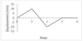
The displacement cycle corresponds to those referred in [16]. The top side of the plate submitted to a horizontal movement of 10 mm to the right, then a 20 mm movement to the left and another 10 mm to the right to return to the equilibrium position (see Fig. 8). This limits the calculation of EDC only in first cycle, since it is implicitly considered that failure is not present in such cycle. A further study is necessary to extend the results for higher cycles that involve comparison with experimental results. It is important to mention that the EDC is directly calculated by Abaqus, otherwise it would be necessary to use a numerical integration method on the hysteresis curve.
5. Results
Fig. 9 shows the state of Von Mises stress in the analyzed plates after applying load cycles and their corresponding estimated energy dissipation capacity (EDC). The entire image presents a stress scale that ranges between a value of 12.6 MPa (dark color) and 485.5 MPa (light color). It is also possible to appreciate the high discretization of the mesh used, which was automatically defined in Abaqus. Thus, it is possible to visually determine the zones in the plate that present high stress values and those that did not contribute to the dissipation of energy. The more material presents high stress levels the higher the EDC will be. This result raises the question: What would occur with plate EDC if the material in zones with low stresses is withdrawn? This is an important question to answer given that less material implies less costs. Topology structural optimization could be applied in order to determine the optimal shape with the highest EDC.
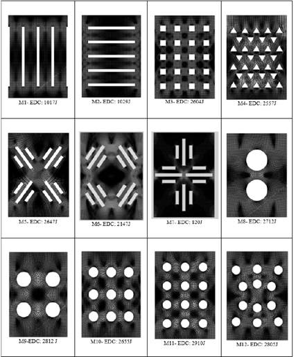
It is important to try to understand the relationship between plate shape and its EDC through stress distribution throughout the plate. Fig. 10 shows that plates with high stress levels around their center result in a larger energy dissipation capacity. Thus, the slits in a plate should be addressed to facilitate that the central zones in the plate to be stressed. The plates with circular slits (M8 to M12) present the highest values of EDC given a better use of the material, presenting low stresse zones in the middle of groups formed by 4 slits. Despite that the difference in EDC values is low (255 J), it can be said that there is no relationship between the number of slots and EDC. Additionally, when comparing the results for plates M11 and M12, it can be concluded that the spatial distribution of slightly affects EDC. The above results would indicate that for a plate with specific width and height, it would be necessary to determine the optimal quantity and distribution of circular slits. On the other hand, EDC is low in plates that present larger rectangular slits (M1 and M2) due to presence of high stresses only around slit corners. Considering that the rest of the material is not used. In this case, slit orientation did not significantly influence EDC. However, a comparison in stresses of plates M5, M6 and M7 shows that the orientation assigned to slit pattern (maintained in the three cases) considerably influenced stress distribution. The best slit placement was oriented to the center of the plate. The above results confirm the need to follow an optimization approach in order to determine optimal shape.
Fig. 10 shows the hysteresis cycle for 8 plates presenting different slit shapes, which correspond to the plates with the highest EDC. All the plates presented a similar shape for the hysteresis cycle, however, with a different area. The plate with the highest area (highest EDC) was plate M11 as mentioned previously. Additionally, it is possible to observe that stiffness is lower after the first maximum displacement. It is important to mention, that this geometrical configuration presented the highest initial stiffness as well. This behavior could be different if more load cycles were included in the analysis.
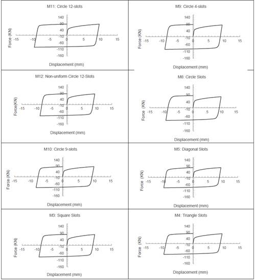
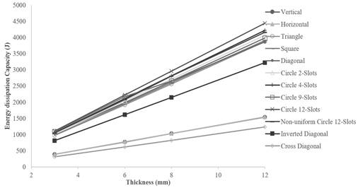
Fig. 11 shows the influence in the energy dissipation capacity of each plate as a function of its thickness. In all cases, the relationship is linear, albeit depending on slit shape, the influence can be more pronounced. This result was expected due to the type of finite element used to model the plate. A more detailed analysis should use solid elements that can consider the effect of a transversal response of the plate as thin plates could suffer buckling. Also, a non-linear relationship could occur if more than one load cycle is carried out, this is because there is no guarantee for uniform hysteresis cycles.
6. Conclusions
Numerical results of steel damper slit modelling showed that such devices could be adequate in order to dissipate energy under cyclic loads. But as seen in the definition, slit shape plays an important role when trying to maximize the EDC of dampers.
It can be concluded that the most efficient shape is the circle given that it provides a better flow to forces that the plates are subject to. Circles also eliminate the variable of orientation in slits, which can greatly vary the EDC as seen in M5, M6 and M7, where M5 focuses stress in the center of the plate, M6 drives it to the sides, and M7 also focuses stress towards the center but lacks material where needed. The variable that least impacted plate EDC was the quantity and size of slits, M1 and M2 had same shape, different quantity and size but only a low variation of EDC (12J), and the same can be seen in plates M8 through M12 where the difference of EDC was only 255J. Lastly, plate thickness directly impacts EDC, as one increases so does the other and vice versa.
One last phenomenon that can be noted from these experiments can be observed in plates with higher EDC, especially M11, M12, M8 and M5. In these plates, high stress flow produces an hourglass shape directing the forces to the center of the plate. This is a possible reason why M1, M2 and M7 have the lowest EDC, being that the slits on these plates interrupt or invade the space close to the center.

