


 Inglés (pdf)
 Articulo en XML
 Referencias del artículo
 Enviar articulo por email
 Citado por SciELO
  Citado por Google
  Similares en
SciELO
Similares en
SciELO  Similares en Google
 Permalink
1. Introduction
Pollution screamed by the consumption of energy in the world, leads us to reflect on the problem caused by fossil fuels and the possible solutions for a healthy environment. The possibility of increasing electricity production without polluting the environment can be achieved by the use of wind fields for that the technology of wind turbines is in constant development. Currently, Algeria is one of the leading countries in improving the efficiency of vertical and horizontal axis wind turbines and optimizing their produced energies. Over the past few years, several researchers have worked on the modeling and the numerical simulation of VAWTs aiming to improve the design and overall performance of these wind turbines. Brian Hand and Andrew Cashman [1] have written a review on the historical development of the vertical type wind turbine of the lifting type. They expressed the development of the vertical axis wind turbine of the elevator type (VAWT) from its implementation in the 1930s to the present day. In industry and the wind energy market, HAWT is predominant, but now VAWT wind turbines have been introduced to the renewable energy market- especially offshore floating wind turbines. Moreover, Jie Su & al, have improved the aerodynamic performance of a VAWT wind turbine by using a new V-shape structure, according to the results they have found, their model is very efficient compared to the rudimentary model [2]. Antonio Posa [3] utilized the simulation to see the influence of the speed ratio (TSR) on the wake characteristics of a vertical axis wind turbine (VAWT). He also studied the sensitivity of wake properties on TSR. Alexander AS and Santhanakrishnan A [4] carried out a simulation-based study to distinguish the mechanisms of power increase in two neighboring vertical axis wind turbines. They concluded that there is an improvement in the performance of a vertical wind turbine with a double rotor compared to a VAWT with a single rotor. M. Zheng et al. [5] Simulated 3-blade, 5-blade, and 6-blade drag-type wind turbines (VAWT) using digital Ansys software, to see the effects of the number of blades on wind turbine performance (VAWT). They found out that the stability of VAWT, as well as the maximum energy efficiency, increase with the number of blades; however, the ratio of the width of the blade to the radius of the turbine which is fixed will be reduced. In order to test the performance of a vertical axis wind turbine, one has to consider several factors such as the number of blades, the profile of the blades, the aspect ratio, the Reynolds number... Arti Tirkey et al [6] numerical analysis to observe the increase in the Reynolds number which directly influences the production of energy. Other authors have studied the performance of Gorlov vertical axis wind turbines and they have made a parametric assessment of them. Much research has been done on vertical axis wind turbines (VAWT), but unlike other researchers, Mahdi Moghimi and Hadi Motawej [7] have extended a low-cost model to compare and estimate the aerodynamic performance of VAWTs with straight blades like Gorlov and Darrieus. They have proven that the performance of the Gorlov rotor is excellent in terms of efficiency and fluctuations. To maximize the energy of a wind turbine, Yan Li et al [8] used a wind collection device (WGD). A 3D digital simulation was made to distinguish the static and dynamic performance effects of the wind collection device on the vertical axis wind turbine with straight blades. HL Bai and all [9-10] made a comparison between the vertical axis wind turbine of the Savonius type in open space and another in a channel. In this numerical study, the authors showed the performances of the latter based on the two-dimensional simulation (2D) and using the k-w turbulence model of the shear stress transport (SST). In another work, they studied the positive coupling of two VA-type Savonius co-rotations using a dynamic simulation of computational fluids (CFD). In the literature, several other studies have been done to evaluate the aerodynamic performance of vertical axis wind turbines. Abdolrahim Rezaeiha et al [11] have proven by numerical simulation that the strength and the number of blades influence the aerodynamic performance of VAWTs. They used different numbers of blades (2, 3, and 4) and they showed that the strength varies over a wide range (0.09 to 0.36). Aiming to have a very quiet vertical axis wind turbine, Jie Su et al [12] have improved a numerical simulation to evaluate the aerodynamic noise of a vertical axis wind turbine (VAWT). They studied the consequences of increased turbulence, increased rotational speed, and distance from the receiver. They found that thickness and charge noise are the dominant sources of noise. The number of blades plays a very important role in studying the performance of a wind turbine. Pongpak Lap- Arparat et al. [13] worked on optimizing the energy produced by the VAWT hybrid wind turbines, they used a fuzzy load control by pulse width modulation PWM. The control of blade pitch in vertical axis wind turbines (VAWT) is not very answered; this is due to permanent changes in the angle of attack of the blade and the relative speed of the wind. Linjun Chen et al. [14] designed a system that can control the feedback pitch angle for wind turbines (VAWT) in real-time. SB-VAWT vertical-axis wind turbines with straight blades are frequently influenced by aerodynamic losses which are excited by the dynamic stall. Zhu et al. [15] used the passive flow control (PFC) method because it has zero energy consumption and a very low cost. You-Lin Xu et al. [16] invented and produced a new blade pitch control device for a high-strength straight-blade vertical axis wind turbine. This control technique has improved the generation of energy. In recent years, several experiments have been carried out to improve the performance of vertical axis wind turbines. Antoine Vergaerde et al. [17] improved the power of a Darrieus vertical axis wind turbine of twin form, by an experimental study. They used wind tunnel tests to note an increase in the power coefficient of the VAWT twin configuration wind turbine. Other researchers [18] have used the blade morphing technique to optimize the dynamic shape of a vertical axis wind turbine. They considered a new design for a vertical axis wind turbine (VAWT) which dynamically changes the blades as a function of the tip speed ratio (TSR) and the azimuth angle. To improve the automatic start-up capabilities of a vertical axis hybrid wind turbine, Arian Hosseini and Navid Goudarzi [19] proposed a new VAWT hybrid configuration. The latter is composed of a Darrieus turbine with 3 blades and a Savonius Bach-type rotor with 2 blades. To evaluate the performance of the designed VAWT hybrid, they used the ANSYS mesh. Abdul Latif Manganhar et al [20] carried out an experimental study on vertical axis micro-wind turbines. To improve the power coefficient of the rotor, they produced an optimized model that consists of a three-blade soapies rotor and a rotor house (RH). Yichen Jiang and all designed a double VAWT system. To improve performance, they added a deflector, the first system without a deflector is used for high and medium speeds. Both discs, the system with deflector, are operating at low speeds. They obtained an increase in output power of 38.6% [21]. Regarding low-speed urban wind turbines. T. Micha Prem Kumar et al. [22] carried out an experimental study on vertical axis wind turbines with a form H shape rotor. To improve the performance of the latter, they used a comparison between wind turbines with inclined blades and without tilting of blades. Since changes in the Reynolds number are due to the aspect ratio of the wind turbine, therefore the performance of the wind turbine will be affected by variations in the aspect ratio which is related to the change in the power coefficient. S. Brusca et al. [23] invented a design for a vertical axis wind turbine to see the effect of the aspect ratio on the performance of a VAWT wind turbine.
The objective of our study is to know how to consider the effect of the number of blades in the performance of the vertical axis H-shaped wind turbine. The Betz coefficient, the speed of the peak ratio, and the torque coefficient have been selected as important parameters of the VATW. An experimental study of VATWH has been achieved by considering the dimension of a finely specific geometry, such as the height, width, and bracket fixed diameter.
2. Theoretical study
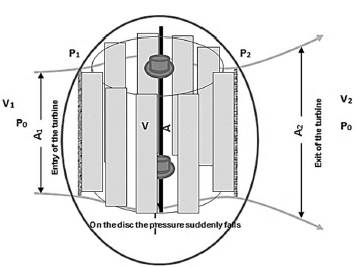
The diagram in the corresponding figure represents the vertical axis wind turbine showing the area of the entrance and the exit represented by the symbols A1 and A2. Of course, the flow of the wind when it touches the edges of the turbine makes it open with an area A2 that is greater than the entrance area of the turbine, knowing that the speed at which the turbine enters is greater than the exit, given that it circles with it, and this is to use it to move the turbine. Therefore, the speed of the entrance is greater than the speed of the exit see Fig.1. And due to the presence of forces that contribute significantly to moving the turbine, we have recorded the pressure caused by the flow of the wind, and based on that, we needed pressures between the two ends of the turbine.
Based on the radial momentum theory, the following assumptions are made:
The flow is completely radial (the air undergoes a rotational movement).
The flow is incompressible.
The wind speed is constant far from the plane of the rotor.
The flow is rotationally symmetrical.
Air passes through the rotor without friction.
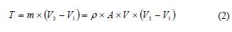
Also by applying the theorem of variation of the momentum, the radial force of the wind on the rotor is given by the following expression:
Applying the Bernoulli equation upstream of the rotor:
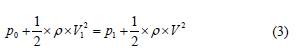
and that downstream:
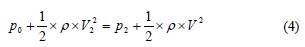
By combining (3) and (4), we obtain
Knowing that:
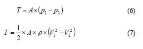
The two equations (2) and (7) allow to write:
The speed of the airflow through the rotor is the average of the two speeds that upstream and that downstream of the rotor.
The power extracted from the wind is:
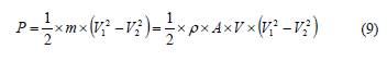
The two equations (5) and (9) allow to write:
Sometimes the velocity V becomes the speed of the wind turbine.
The power coefficient Cp is defined as the ratio between the available wind power and the extracted power:
2.1 Aerodynamics
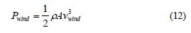
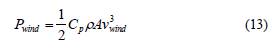
The wind power engenders between both systems estimated by the wind turbine rotor and the wind. The principal aerodynamic of wind turbines were carried out by Betz [25] and Glauert [26]. The wind power is given by:
2.2 Betz limit
The coefficient of Betz represents the ratio between the power turbine estimated the mechanical power of the turbine and the wind power. The Beltz limit is determined by a maximum turbine power of 59.26%, which means the maximum wind power used with the coefficient of Betz by 0.5926. The ratio of extractable power to available power is expressed as the rotor power coefficient Cp.
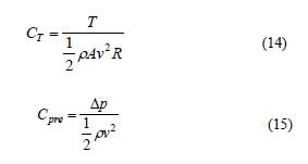
We also have other parameters estimated by the coefficients of torque (CT) and surface static pressure (CPre) of the wind turbine, which are defined, as below:
3. Experimental setup
The experimental study was undertaken in the department of Mechanical Engineering at the University of Biskra. The construction of the vertical axis H-shaped wind turbine included blades by the galvanized material- 60 cm high and 12 cm wide.
The H-shaped vertical axis wind turbine was made in the hall of the University of Biskra, where the research was manifested in the study of the dimensions imposed in the experiment from the length of the propeller and the extent of its curvature in the width of the propeller. Several numbers of the vertical axis win turbine cycles were recorded using a device that measures the number of rotation as well as the force of torque in the device digital balance which is connected to the side of the turntable of the turbine and taking into account the pressure drop confined between the sides of the turbine. The process was done according to the number of times that the blades are replaced and are as follows: 10, 14, 16, 18, and 20. The device was placed in the laboratory for aerodynamic experiments in the lobby, by placing it at a distance of 2 m from the source of wind every time. See Fig.2. It changes the speed of the device from 3 to 15 m/s.
3.1 Measuring instrument
An electronic balance is a scale with a stand that carries the masses to be weighed and contains a monitor with a 1/1000 accuracy, see Fig.3. The purpose of its use is to find the torque force resulting from the wind turbine each time we change blades and this is to calculate the torque and use it to calculate the capacity of the wind turbine from the solver of the electronic scale, its value is multiplied by 10 to obtain the motive power of the turbine.
• Tachometer:
It is a device that is used to measure the number of revolutions- i.e. a rotating body. It is an effective way to know the number of revolutions, and this is to find out the angular velocity of the wind turbine as the contributor is built into the capacity calculation of the wind turbine, see Fig.4.
• Wind tunnel
It is the device of the air channel where it can change the velocities and the movement of air in the channel. It is used to measure the forces hindering the bodies and shapes whose dynamic movement is to be studied from traction and tangential forces, in order to find out how well-complicated shapes can tolerate how well they feel with the movement of air. As for our experiment, we used it to create the movement of air to circulate the wind turbine with the ability to control the wind speed. See Fig.5.
• Anemometer:
A device that is used for measuring both: wind speed and temperature, see Fig.6. In our experiment, we dedicated it to measuring the entry and exit points of the wind. Also, the accuracy of the measurement is limited between the speeds of 0 to 3 m/s, and it is 0.01 m/s
• Differential pressure
The pressure drop is a very important device in this experiment because it is through which we can record the pressure placed on the edges of the inlet and outlet of the wind turbine, and of course, it is possible to calculate the mechanical capacity of the wind turbine so this is an important element to calculate the cost-effectiveness of this turbine, and we increase it knowing that its accuracy is with a value of 1 Pa and the marginal value of the measurement is 100 Pa, see Fig.7.
4. Result and discussion
Fig. 8 shows the variation of the rotor power coefficient as a function of the speed turbine according to the quantities of the blades. We observe that the coefficient Cp selected with maximum values when the turbine wind, which contains the number of blades equal to 20, and with minimum values by 10 blades, And the value is confined as the boundary value between 0.025 and 0.25. It is noticed that the power coefficient Cp varies as a function of the numbers of the blades used, from Fig.8, we see that for a turbine of 20 blades, the power coefficient Cp vary between Cp min = 0.16 Cp max = 0.23, the speed of the various turbine is paralleled in an interval [min; max] = [0.5; 7.8]. On the other hand, for a 10-blade wind turbine, we notice that it has the same speed, but a speed interval [min; max] = [0.5; 4.6] and a power coefficient Cp varying between two values [min; max] = [0.025; 0.1]. Hence, we deduce that whatever the variation of the numbers of the blades, we always obtain the same form of non-linear curves but with a remarkable variety of Cp.
Source: The authors
Figure 8 Variation of the power coefficient of the vertical axis turbine by shape H.
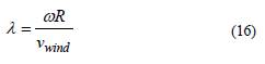
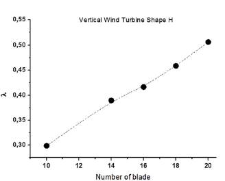
Fig. 9 represents the variation of the specific speed as a function of the number of blades of the turbine. Note that the number of blades influences the specific speed of the vertical axis wind turbine (VAWT), we can also see that the increase in specific speed is proportional to the number of blades. It is noted that the specific speed is linearly increasing with the number of blades of the turbine. This means that there is a relationship between the major characteristics of the aerodynamics of the blades of the wind turbine and their numbers. It is distinguished that the shape of the chosen blade which is in an arc influences the specific speed. According to the linear interpolation, we obtain two constant values A and B which represent the configuration of the H-shaped wind turbine (VAWT) and according to the dimensions chosen, we deduce that whatever the number of blades used always remains in the meantime [10,20].
Source: The authors
Figure 9 Variation of the tip speed ratio of the vertical axis turbine by shape H.
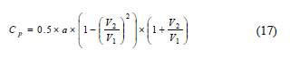
Fig. 10 represents the relationship between the power coefficients of the Form H wind turbine as a function of the output/input speed ratio, according to the number of blades. A relationship has been deduced between the two Figs. 10 and 11; this relationship is expressed by the A2/A1 ratio, which influences the performance of the turbine, specifically the power coefficient of the rotor. Every time this ratio increases, the number of blades decreases, and vice versa. The V2/V1 speed ratio directly influences the A2/A1 ratio, if these speed ratios increase; the power coefficient of the rotor is poor despite the increase in the number of turbine blades. We can write the power coefficient of the turbine using an equation for all sine points 0.49 and 0.77, which represents the quotient of the velocity of the outward air by the velocity of the incoming air. It can be written and represented in the following equation:
Source: The authors
Figure 10 Relationship between the power coefficients as a function of the output/input speed ratio
Table 1 represents the variations of the constant 'a' according to the change in the number of codes for the wind turbine. The writing of the equation without 'a' represents the ideal writing for the original form, and the presence of the constant does not mean that there are some effects directed to the wind turbine and therefore we want to represent them with this constant, which we consider as a percentage concerned with the perfect equation.
Table 1 Constant of the equation eq.17, according to the number of the blade of the wind turbine.
Source: The authors
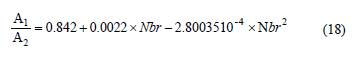
Fig. 11 shows the variation in the product of dividing the area outward- inward to the movement of the air flowing in the wind turbine as a function of the number of turbine blades. We note that the smaller the number of blades in return, the greater the quotient of the divisions of the area, and the approximate one, and vice versa. When the number of blades approximates 14 blades, then we record the quotient of the area by 0.835, and when the number of blades equals 20, we have recorded 0.78. We represented the quotient of the air area in terms of the number of blades. They are written as polynomials of the second order, as they are represented in the following equation eq.18:
Source: The authors
Figure 11 The ratio area in and out of turbine coefficients as a function of the output/input speed ratio
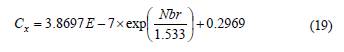
Fig. 12 Represents the change in the total withdrawal coefficient of the wind turbine in terms of the number of blades. We notice from Fig. 12 that the value of the drag coefficient increases with the increase in the number of blades. The latter also increases the friction of air movement with the used blades; this is all based on the conditions chosen in the construction of the wind turbine.
Also, changes in the drag coefficient take the form of exponential function variations; henceforth, we tried to form and write them in terms of the number of blades. Notice the following form of the equation eq.19:
We represented the power coefficient of the vertical wind turbine in terms of the tip speed ratio. They are written as polynomials of the third order, as they are represented in the following equation eq.20:
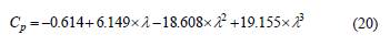
Fig. 13 Represents the variation of the power coefficient according to tip ratio speed, based on experimental and numerical data. This curve shows the variation of the power coefficient whatever the number of blades of the wind turbine with the vertical axis of form H. It is observed that the numerical curve is almost similar to the experimental data. The latter gives a better prediction with a very low calculation error.
We observe that there is a growth in the variation of the power coefficient. It begins with a low value estimated at 0.03 which corresponds to a tip ratio speed value equal to 0.2. The curve continues to increase up to the values [Cp max = 0.6 and λ max = 0.6]. We also note that the variation of Cp constitutes a condensed cloud which is very remarkable between the interval of λ [0.3 and 0.5] for an average value of Cp = 0.17.
Fig. 14 represents the change in the speed of the wind turbine in terms of the speed of entry of air to the turbine, which is calculated through the angular velocity multiplied by the radius of the turbine disk; additionally, the angular velocity is determined by the number of revolutions of the turbine and recorded by the tachometer device.
We note from the previous figure that the variable is a linear function and its inclination represents the quotient of the velocities, and we have recorded that the greater the number of blades in return, the greater the linear velocity of the wind turbine, and vice versa.
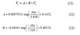
Eq. 21 represents the linear function of the speed of the wind turbine in terms of the air velocity at the inlet. As we concluded that the constants A and B change with the number of blades see Table 2, we created in each of the constants an equation written in terms of the number of blades, as shown in equations (eq. 22 and eq. 23).
5. Conclusion
In this experimental study, a new design for a vertical axis wind turbine (VAWT) was carried out. We decided the geometrical values of the blades including the length, the width, and the value of the curvature of the blade on the transverse side, as well as the diameter of the turntable of the turbine with vertical axis. Then, we calculated the capacity of turbine mechanics, using a device that measures the pressure difference between the two points of a turbine. In our experiment, we used the air ejector that exists in the mechanical laboratory whose purpose is to shoot air forces and have an airspeed range that varies between [1.6 and 15.8] m / s.
One of the conditions is to install this device with two masters of our wind turbine in order to have very effective and very precise measurements. Among the most important points of the experiment was to record the number of revolutions of the turbine using a contact tachometer equipped with a wheel type tip to measure the number of revolutions of a turbine and optimize the turbine rotation number.
The mathematical model establishes the relationships which exist between several parameters- such as the power coefficient, the speed of the wind turbine with a vertical axis, the power coefficient, and the specific speed. The R2 errors and X2 have the most minimum values. This study highlights the influence of the numbers and shape of the blades on the speed and power of the wind turbine.

