


 English (pdf)
 Article in xml format
 Article references
 Send this article by e-mail
 Cited by SciELO
  Cited by Google
  Similars in
SciELO
Similars in
SciELO  Similars in Google
 Permalink
1. Introduction
One of the key elements to preserve the well integrity on the long term is the cement [1]. One of its main objectives is to provide full and efficient zonal insulation during the well's entire useful life [2]. The experience, laboratory studies, and actual field cases have proved that, even though primary cementation has been successful and initially cement performs its sealing functions effectively, changes may occur in the pressure and temperature conditions due to the well's operative life which induce stresses through the casing and the formation, capable of deteriorating the integrity of cement and cause its mechanical failure [3]. One of these types of failure is by debonding in its interfaces, which causes undesirable phenomena such as sustained pressure behind the casing, uncontrolled interzone flow, and leak of fluids towards the surface that lead to severe technical, economic, and environmental problems [4,5]. Therefore, modeling the mechanical failure on the interfaces is a significant step to avoid the aforementioned problems and ensure the safe operation of the well. Debonding of interfaces may be modelled as a tensile or shear failure [4]; therefore this paper consisted on evaluating these failure modes in the casing-cement interface by applying the Bradley (1979) tensile failure criterion for tensile failure and the Mogi-Coulomb failure criterion for shear failure from the main stresses obtained as the temperature of the well and the formation increase and the well pressure and the formation pore pressure decrease during the production, taking into account that this criterion considers the true 3D stress state to which the cement is subjected downhole, which is provided by the numerical model. The model was developed in the ABAQUS® software which simulates the construction of the well by means of an approach per steps, where each one of those represents an operative stage. The drilling stage is validated by means of the analytical models of Kirsch (1898) [6] and Bradley (1979) [7], and the completion stage with the analytical models of Teodoriu et al. (2010) [8] and De Simone et al. (2017) [9], comparing the radial stresses obtained in the materials after iterating each stage. Last, the investigation of the effect of pressure and temperature changes on the tensile and shear failure of cement is done from the finite elements' analysis and the application of the failure criteria on the casing-cement interface.
2. Reference framework
Numerous papers have been developed since the 1990s to study the long-term mechanical behavior and likelihood of failure of cement under different circumstances. Recently, [10] developed a thermo-poroelastic numerical model to evaluate the integrity of cement according to its thickness. [11] presented a 3D poroelastic finite-element (FE) model coupled with cohesive regions to represent fracture propagation during hydraulic fracturing. [12] used a simulation tool based on a thermo-chemo-poroelastoplastic approach to estimate the evolution of the stress state, shrinkage and pore pressure of cement versus the degree of hydration. [13] presented a thermo-chemo-poro-elastoplastic model to predict pore pressure and initial stresses in cement. [1] developed a 3d FE model to evaluate the effect of the orientation of in situ stresses, rigidity of the formation and eccentricity of the casing in the integrity of the cement. [3] presented a 2D FE model to evaluate the properties of the material, geometric parameters, and stress conditions at the origin of cement failure. [14] showed a chemo-poro-elastoplastic model capable of predicting the initial stresses on cement, as well as the possible origin of micro annuli during cement dehydration under different temperature and pressure conditions. [15] used a 3D FE model to develop sensitivity plots for design and operation parameters, such as cement properties, wellbore pressure and annulus pressure; and [16] conducted finite elements analyses to evaluate the critical variables in the origin of failure caused by debonding on the interfaces and formation of micro annuli.
These previous works have proven to be relevant for the study of cement integrity. However, the model developed in this study takes into consideration the elastic, plastic, and thermal characteristics of the cement, and in the formation; additionally, it includes the porous characteristics, which have proven to be important for the study of mechanical integrity problems of materials and provide a more realistic approach to the numerical model.
3. Constitutive models of the materials
The model used to describe the mechanical behavior of the casing-cement-formation set implies, as starting point, the use of constitutive models that reflect the internal characteristics of the material in the form of macroscopic properties [17]. In this way, the casing and the cement are considered as thermo-elastoplastic materials, while the formation is a thermo-poroelastoplastic medium. Although the cement and the formation behave in a non-linear manner subject to great stresses, their behavior may be approximated by means of linear ratios in the range of infinitesimal deformations; therefore, the behavior is presented initially as linear elastic, modeled by means of Cauchy's stress [18].
Beyond the elastic limit, where deformations are irreversible, the behavior of materials is ductile and for the purposes of this paper, it is governed by the Mohr-Coulomb plasticity model [18]. Deformations of mechanical origin are also accompanied by expansions and contractions caused by temperature variations due to the operation of the well [17]. Materials expand or contract with temperature increases at different velocities according to their own thermal properties [19], which might cause mechanical failure of cement or debonding on its interfaces.
Therefore, the thermal effect is included in the numerical model, considering that the only mechanism of heat transfer is by conduction. For this purpose, the differential equations of 3D heat conduction in cylindrical coordinates, in steady state and without internal energy storage, were used [20]. Finally, to consider the geological formation saturated by a fluid, the poroelastic model was integrated, which represents the porous medium using the conventional approach based on the effective stress principle [21]. It is assumed that the total stress acting at a point (σ) is composed of an average fluid pressure stress, or pore pressure (p p ), and an effective pressure stress (σ') defined by eq. (1):
Where x is a factor that depends on the saturation and surface tension of the rock/fluid system whose value is 1.0 when the porous medium is completely saturated and / is the identity matrix.
4. Numeric modeling
This paper considered a 3D computational domain of a well section composed of the fully bonded casing-cement-formation system, with the objective of analyzing the effect of pressure and temperature changes on the mechanical integrity of the cement in contact with the casing.
4.1 Mathematical considerations
The model considers historical and current data of stresses, strains, and temperatures of the materials to perform the analysis. The model was developed using finite element discretization using ABAQUS® software, deeming the following assumptions.
The casing and the cement are homogenous, isotropic, continuous, non-porous, and impermeable materials and their behavior is thermo-elastoplastic.
The formation is a homogenous, isotropic, and thermo-poroelastoplastic material.
The geometry of the model is axisymmetric, due to boundary conditions, where the axis of symmetry is the vertical axis of the well, allowing the use of a global cylindrical coordinate system.
The directions of the main in situ stresses match the axes of this global system.
To model the plastic response of the casing, cement and formation, the Mohr-Coulomb plasticity model was used, whose initial absolute plastic deformation is considered equal to zero for all materials. The materials are perfectly mechanically bonded to each other at their respective interfaces. The potential failure at the casing-cement interface was evaluated using the failure criteria. The formation is a porous medium 100% saturated with singlephase fluid and has infinite boundary conditions. The mechanical behavior of the cement after complete set is analyzed, which means that neither the mechanical interaction between the cement slurry and the formation, nor the shrinkage/expansion of the cement is included. To overcome this limitation, an initial stress state is imposed on the cement, equivalent to the hydrostatic pressure of the slurry.
4.2 Model geometry and conditions
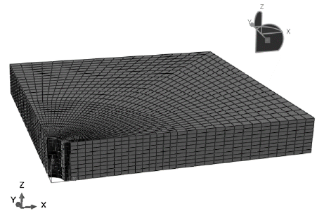
The numerical model developed corresponds to one fourth of the total structure of a vertical wellbore. The remaining portions may be generated using ABAQUS's mirror function [22]. Following a numerical mesh sensitivity study to determine the dimensions representing the object of study, based on the convergence of in situ stresses on the end of the model, a parallelogram of 1.80975 x 1.80975* 0.254 m, where 0.254 m represents the thickness, was established for the formation. The horizontal dimension/radius ratio is 15 times, in order to represent infinite boundary conditions and to suppress the edge effect in the simulations. The casing and cement are represented as concentric cylinders of uniform thickness, the internal diameters of the casing, cement and formation are 0.168402 m, 0.193802 m and 0.2413 m, respectively. The section of the casing-cement-formation system represented is located at 4572 m depth, it is considered that there are no variations of the quantities of interest across the axial axis, since the total thickness of the model is approximately equal to the size of the wellbore.
Each material was discretized with finite elements for numerical processing. The formation is discretized using 8-node hexahedral linear elements with trilinear displacement, pore pressure and temperature and reduced integration, C3D8RPT, and the casing and cement were discretized using 8-node hexahedral linear elements, thermally coupled, with trilinear displacement and temperature, reduced integration and hourglass control, C3D8RT. The advantages of elements with reduced integration are that stresses, and strains are computed at locations that provide optimal accuracy, and these integration points decrease computational time and storage requirements [20,23]. Fig.1 shows the meshed model with 5200 elements on the casing and on the cement and 12000 elements on the formation. The type of meshing performed was structured. This technique provides greater control over the mesh since it applies pre-established mesh patterns to particular model topologies.
Because a quarter of the total structure of the system is modelled, symmetry boundary conditions (no motion, no rotation) are applied on the x and y lateral faces opposite to the x and y faces where in situ horizontal stresses are applied. Vertical displacement is also constrained by applying a no-motion-no-rotation boundary condition at the base of the model. An embedment is applied at the wellbore face during the equilibrium step of the model to represent that the rock is still undisturbed, which is removed in the drilling step. A 3D in situ stress system acts orthogonal to each other in the formation: at the top surface of the formation the overburden stress is applied (parallel to the z-axis), and the maximum and minimum horizontal principal stresses are oriented along the x and y axes, respectively (Fig. 2). Initial pore pressure, saturation, void ratios, and temperature are applied to the formation. Table 1 shows the initial load conditions and the ones applied during each operative stage.
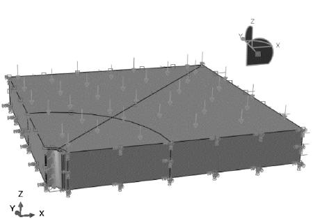
Table 1 Initial load conditions and the ones applied during each operative stage.
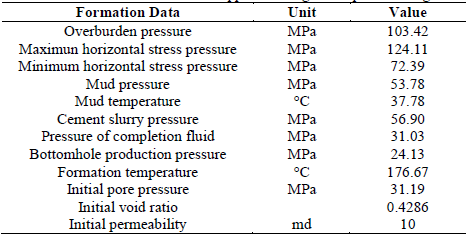
Source: Adapted from [19]
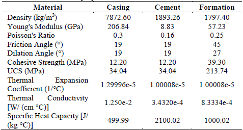
The casing and the cement are thermo-elastoplastic materials while the formation is thermo-poroelastoplastic. Table 2 provides the set of properties of the materials used as input for the baseline case.
4.3 Simulation stages
Five stages were simulated, each one representing an operative stage of the wellbore.
Equilibrium. Corresponds to the initial equilibrium state of the model, before drilling the rock. The formation block is subjected only to the state of in-situ stress, in-situ temperature, and pore pressure. Equilibrium is achieved by setting the respective boundary conditions. The wellbore face is fitted to represent the formation before it is drilled. The analysis procedure specified in this step is Geostatic. In-situ stresses remain unchanged through all sequential steps.
Drilling. After iterating the equilibrium step, a stress state is generated, which is a modification of the stress field defined by the initial conditions. This field represents the initial 3D stress state in the fully coupled porous fluid flow-stress analysis with steady-state heat transfer specified in this step. This type of analysis is also specified in the subsequent steps. The drilling of the hole is represented in the model by removing the casing at the wellbore face to apply the mud weight there. The drilling mud exerts pressure on the well face maintaining the equilibrium of the drilled rock.
Casing and Cementing. In this step, the elements corresponding to the casing and cement materials are activated using the ABAQUS model change function. These elements are activated without initial deformation, but under an initial stress state, equivalent to the hydrostatic pressure of the slurry, i.e., the initial state of hydrostatic compression due to the slurry is imposed on the cement.
Completion. During this step, the completion fluid is placed inside the casing. The hydrostatic pressure exerted by the fluid on the internal surface of the casing depends on the density of this fluid [19,23].
Production. Similar to the effect in the completion step, during well production, the hydrostatic pressure inside the casing is reduced and its magnitude depends on drawdown and pore pressure.
4.4 Failure criteria
In general, there are two failure modes of cement: shear failure and tensile failure. These failure modes may be caused due to the operative loads and propagate in different directions, becoming potential leaking pathways of formation gases or fluids [24], o prediction of cement failure is important to maintain well integrity. Because the mechanical behavior of cement is different under tension and compression, different failure criteria are used for each failure mode.
The criterion formulated by Bradley (1979) was used in this paper for the tensile failure, which specifies that the failure originates when the negative of the maximum resistance to uniaxial tension of cement (T0) is equal or greater than the minimum principal stress (σ 3). This mathematical inequality is expressed as σ 3 ≤ -T 0 .
For shear failure, typically, the Mohr-Coulomb failure criterion, which relates two strength parameters (unconfined compressive strength, UCS, and angle of internal friction, ф has been employed [2,24], without considering the effect of intermediate stress, which might be useful when there are conventional triaxial data available. However, when true compressive strength data are applied, the Mohr-Coulomb failure criterion could generate significant errors [24].
Downhole, the cement is subjected to a true triaxial stress state, so it is not guaranteed that this is the appropriate criterion. Therefore, the Mogi-Coulomb failure criterion is used in this study, which relates the same strength parameters as Mohr-Coulomb (UCS and ф) [2] and has been experimentally proven to be the best for evaluating shear failure [24].
The linear Mogi-Coulomb failure envelope is defined in terms of the octahedral shear stress (т осt) and the mean stress (σ m , 2 ) according to eq. (2)-(3):
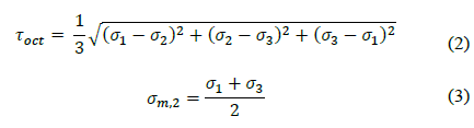
Where σ 1 ,σ 2 and σ 3 are the maximum, intermediate, and minimum principal stresses, respectively.
In this paper, the effect of the same variables on both tensile and shear failure at the casing-cement interface is investigated using the aforementioned failure criteria.
5. Analysis of results
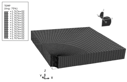
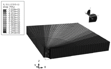
After iterating the equilibrium stage, it was found that the rock is indeed in a state of thermal and mechanical equilibrium. In the first case, it preserves the temperature in situ throughout the formation block (Fig. 3) equivalent to the formation temperature (Table 1) applied at the beginning of the stage. Similarly, in the second case it is observed that the maximum and minimum horizontal stresses are distributed through the x and у axes in the formation block, respectively (Fig. 4), which correspond to the values of horizontal stresses in situ (Table 1) specified before the iteration. According to the above, it is guaranteed that the formation is in complete equilibrium before being drilled.
The drilling stage is verified by wellbore stability analysis, comparing the radial stresses (σ r ) obtained through the formation radius in the x-direction, with those calculated using the analytical equations published by Kirsch (1898) [23] and Bradley (1979), to represent the distribution of radial stresses generated around the vertical wellbore face and in the formation after being drilled. Also, the well completion stage is verified by comparing the radial stresses obtained through the radius of the materials, for an azimuthal angle equal to zero measured with respect to the x-axis, with those calculated using the analytical models published by Teodoriu et al. (2010) and De Simone et al. (2017), to estimate the stress distribution through the casing-cement-formation after well completion.
In the drilling stage, the results show that, in general, the highest stress divergence occurs near the borehole face the region where the perturbation occurs, and decreases as the radial distance (r) from the borehole axis increases (Table 3). This trend is as expected; away from the borehole face the radial stress should be approximately the maximum horizontal in situ stress, as shown by the convergence of results from the three models (Fig. 5). Deformation from drilling mud pressure can lead to the development of plastic regions at the wellbore face [23], which explains why the differences in results near the wellbore face are larger.
Table 3 Radial stresses (σ r ) comparison between the numerical and analytical models of Kirsch (1898), and Bradley (1979) in the formation, at the drilling
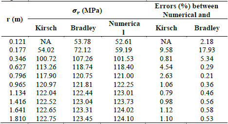
Source: The authors.
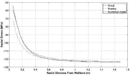
Source: The authors.
Figure 5 Radial stresses obtained with the numerical model and with the analytical model of Kirsch (1898) and Bradley (1979) in the formation at the drilling stage.
On the other hand, the radial stresses (σ r ) obtained in the completion stage also have convergence towards the maximum in situ horizontal stress as well as the ones obtained with the analytical models of Teodoriu et al. (2010) and De Simone et al. (2017) (Fig.6). Table 4 shows the percentage differences obtained between the numerical model and the analytical models, similar to the drilling stage, in general, they decrease as the radial distance from the borehole axis (r) increases. The largest discrepancies between the results occur in the casing region. This divergence of results is mainly caused by the modeling technique [25] i.e., the analytical models are based on generalized plane strain, which are pseudo-3D models while the numerical model is perfectly 3D.
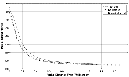
Source: The authors.
Figure 6 Radial stresses obtained with the numerical model and with the analytical model of Teodoriu et al. (2010) and De Simone et al. (2017) in the casing-cement-formation at the completion stage.
Table 4 Radial stresses comparison between the numerical and analytical models of Teodoriu et al. (2010) and De Simone et al. (2017) along the well completion stage, through the casing-cement-formation in the x-direction.
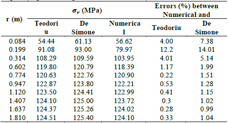
Source: The authors.
The good convergence between the results of the numerical model and the analytical models in the drilling and completion stages validate the finite element analyses presented below, performed using the developed model which offers significant advantages over analytical models based on generalized flat deformation, that is, they are not perfectly three-dimensional: stress-deformation analyses do not only involve horizontal stresses induced in the plane, but also takes into account vertical stress; it uses a staged approach which simulates the construction of the well from before drilling the rock, so, in the model, the components exhibit historical dependence, that is, take into account the history of thermal and mechanical stresses and loads imposed during each of the operational stages of the well; includes properties of materials that are excluded in analytical models, such as density, thermal conductivity, specific heat capacity, internal friction angle, expansion angle, cohesion, formation permeability, vacuum ratio (porosity) and rock saturation, among others, which expand the field of study related to cement mechanical integrity; and, additionally, it is possible to perform finite element analysis at the coating-cement and cement-forming interfaces, and through the cement body or any other region or node, with high degree of precision.
The analysis of the effect of each variable on cement shear and tensile failure is performed by obtaining the principal stresses at the casing-cement interface using the numerical model at the production stage and the subsequent application of the failure criteria described above. Each variable was evaluated while the others were kept constant, in order to study the exclusive effect of the variable of interest on the mechanical integrity of the cement in contact with the casing. The material properties and loading conditions of the model, for all analyses, are the same as those of the base case presented in the numerical development, summarized in Tables 1-2.
5.1 Effect of formation and wellbore temperature rise on cement shear and tensile failure
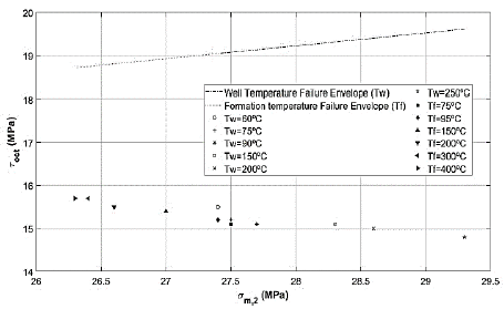
Fig. 7 shows the effect of temperature change of the formation (T f) and the well (T w ) in the cement shear mechanical failure. The linear Mogi-Coulomb failure envelope is the same in all the analyses, since Young's modulus, internal friction and cohesion of cement do not vary. As the formation temperature increases, the values of τ oct vs σ m , 2 are monotonically approaching the failure envelope; in this manner, the probability of shear failure in the casing-cement interface increases with the formation temperature. Additionally, Fig. 7 shows wellbore temperature increases, the values move monotonically away from the envelope, then the probability of shear failure in cement in contact with casing decreases as wellbore temperature increases.
Source: The authors.
Figure 7 Effect of the variation of the temperature of the formation and the well on the mechanical failure of the cement shear.
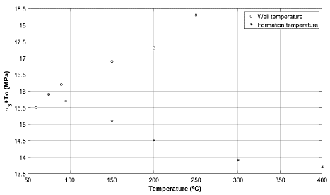
Fig. 8 shows the effect of changing formation and wellbore temperature on the tensile failure of cement in contact with the casing. As the formation temperature increases, the values of σ 3 + τ 0 monotonically approach zero; if the T f continued to increase, the inequality σ 3 + τ 0 < 0 would be fulfilled, hence tensile failure would originate. Considering this, the probability of tensile failure at the casing-cement interface increases with the formation temperature. On the other hand, as T w increases, the probability of tensile failure at the casing-cement interface decreases.
5.2 Effect of increasing formation and wellbore pressure on cement shear and tensile failure
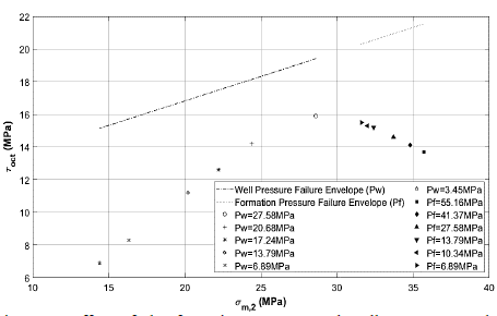
Fig. 9 shows the effect of decreasing formation pore pressure (p p ) and wellbore pressure (p w ) on the shear failure of cement at its contact with the casing. As the pore pressure decreases, the values of τ oct vs σ m,2 monotonically approach the linear failure envelope, indicating that the probability of shear failure in cement at its contact with the casing increases as the pore pressure decreases. Fig. 9 also reflects that as wellbore pressure decreases during production, the values move uniformly away from the envelope, i.e., the probability of shear failure at its contact with the casing decreases as wellbore pressure decreases.
Source: The authors.
Figure 9 Effect of the formation pressure and well pressure on the mechanical failure of the cement shear.
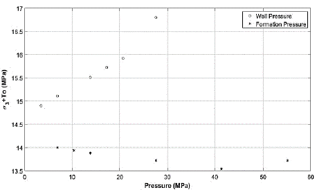
On the other hand, Fig. 10 illustrates the effect of formation and wellbore pore pressure on the tensile failure of cement at its interface with the casing during production. As pore pressure decreases, the values of σ 3 + τ 0 move smoothly away from zero, indicating that the probability of tensile failure of cement at its contact with casing decreases slightly as pore pressure decreases. Finally, as wellbore pressure decreases, the values of σ 3 + T 0 monotonically approach zero, i.e., the probability of tensile failure in cement at its contact with casing increases as wellbore pressure decreases during production.
6. Conclusions
This research presents a 3D finite element model of the casing-cement-formation coupled system to evaluate the effect of wellbore and formation pressure and temperature changes on the mechanical integrity of cement in its contact with the casing during production. The following conclusions were obtained according to the analyses conducted:
The average of the differences obtained in the validation of the numerical model with the analytical models of Kirsch (1898), Bradley (1979), Teodoriu et al. (2010), and De Simone et al. (2017) were 1.26% ± 1.60 SD (Standard Deviation), 2.18 % ± 4.39 SD, 1.78 % ± 2.87 SD and 2.78 % ± 3.41 SD, respectively. The good convergence between the results of the numerical model and the analytical models demonstrate sufficient validity in the finite element analyses performed at the casing-cement interface to determine the tensile and shear failure potential by applying the Bradley (1979) failure criterion for tension and the Mogi-Coulomb failure criterion for shear.
Increasing formation temperature increases the probability of shear and tensile failure in cement in contact with casing during production, while increasing wellbore temperature decreases the probability of these two failure modes in this region of cement.
As the wellbore pressure decreases during production, the probability of shear failure on the casing-cement interface decreases, while the probability of tensile failure increases.
Decreasing formation pore pressure during production increases the probability of shear failure in the cement at its interface with the casing, while decreasing the probability of tensile failure in this region of the cement.
6.1 Future work
Future work includes investigating the effect of other variables on cement shear and tensile failure, such as Young's modulus and Poisson's ratio of cement and rock, cement eccentricity, borehole azimuth and inclination, and investigating these failure modes in other cement regions by finite element analysis using three-dimensional numerical models.

