1. Introduction
According to all existing segments, civil construction is one of the service sectors that has directly benefited from the implementation of technological advances in its processes. In view of this, will be highlighted in this study the contribution of an intelligent virtual program called BIM (Building Information Modeling), which is considered a successful tool in project development.
It is interesting that as one of the main branches of world socioeconomic development, this sector be aligned with the available innovations. In this way, the productive cycle of contemporary constructions will have its management remodeled and constantly updated in view of the most recent design virtual tool discovered. In addition, as a result would be obtained the construction carried out according to the projection previously defined with the aid of the software.
The BIM is a methodology responsible for the practice of numerous compatibilizations between projects during their evolutionary development process. Therefore, many problems are avoided by its ability to identify conflicts. At the same time, the system's parametric attribute allows for automatic building information modeling.
Currently, this engineering software is a system for gathering information into a single document and allowing real-time interchangeability between designers. In summary, the BIM promotes relevant changes in the quality and safety of works and workers through the prior planning of services [1].
In accordance with all this, a case study was carried out to present the interferences found between the specialties analyzed during the compatibilization processes. Finally, the potential of the BIM methodology was identified in relation to the investigation of incompatibilities and the findings of other authors were cited.
1.1. Importance of the compatibility process
The practice of compatibilization emerged from the context of project fragmentation, which was demarcated by the individualized deployment of each project specialty to the detriment of meeting their respective needs, without taking into account the integrality of the process in the development of a project. As a result, the civil construction sector was labeled by lack of rationalization, low level of industrialization, unskilled labor and the great waste of materials [2]. It was from this context that the compatibility of projects became an adopted measure responsible for the reduction of many incompatibility problems between physical interferences, functionality losses and high levels of waste [3].
The procedure for compatibility between the projects is carried out by adapting the divergent elements, so that a solution should be compatible with the dimensional, aesthetic and technological purposes [4]. It’s important to highlight that the compatibility must be carried out in all phases which make up a project, that is to say, from preliminary studies for the subsequent formation of preliminary project to the stages of elaboration of legal projects and finally of executive projects [5].
When the components of a system don’t conflict with each other and show consistency, it can be considered that the compatibility attribute is present in the project, thus describing its reliability [6]. Under these circumstances, the practice of compatibilization is of paramount relevance for improvement the constructability that guarantees the quality of the final product [4]. Therefore, constructability refers to the interaction between the design and execution stages through the compatibilizations with the use of theoretical knowledge and technical experience obtained so far by the professionals involved [7,8]. Accordingly, the purpose of compatibilization is to resolve all interferences between systems so that all elements are well positioned, without encounters and/or overlaps between the horizontal and vertical ways of the installations and that they have an efficient performance.
In order to help make the projects compatible, information and communication technologies are essential for a better use of time and for the wide accessibility of those responsible. In addition to the speed with which the exchange of data takes place that enable more effective solutions to the building [9]. Studies show that the use of technology in the civil construction sector worldwide is limited to the use of AutoCad (Computer Aided Design - CAD) associated with other systems that contribute to the development of structural calculations [10,11].
Nowadays, the process of project compatibility is still very much carried out in the traditionals methods in AutoCad software using a 2D perspective, this is with the overlapping of plans from different project specialties [3,12].
However, the construction sector is gradually realizing deficiencies in this conventional method of analysis in relation to the spatial visualization of the 3D design, in the manipulation and understanding of the elements, among other difficulties that interfere in the project’s productivity. Finally, it’s from this scenario that the timid introduction of BIM occurs initially to change the organizational and cultural form of project design.
1.2. The BIM methodology in civil construction
Among the segmented scenario of the construction industry, BIM (Building Information Modeling) stands out as an efficient tool for integration, collaboration and communication between designers to eliminate redundancies between projects [13]. In this way, a company will end up adopting this technological innovation due to competitive pressure from another, so that this factor becomes a distinguishing differential of services offered in architecture, engineering and construction (AEC) [14].
In a survey conducted by Editora Pini in 2013, 56% of those interviewed stated that they used BIM as a means of analyzing and making projects compatible, with the objective of finding solutions for universal projects between the various systems checking the difficulties encountered [15]. Especially, in the compatibilization phase, the BIM technology presents its potential, providing the virtual simulation of the construction process through parametric three-dimensionality [16]. BIM programs are responsible for creating a complete digital model of any building, also to generating an accurate quantitative list of materials for cost estimation due to coordinated details [17]. BIM has the ability to store datas in a single file which ensures that the integrity and modifications made are managed by the software itself and not by the user. Besides, it gathers information covering the design, operation, management, maintenance and demolition, that is it encompasses the entire project life cycle of a building [18].
For a better understanding of the technological advances that have occurred to date and for a deeper understanding of BIM's capacity, it’s suggested to read the article "Technological Evolution of Project Development in the Civil Engineering and Architecture Sectors" developed by the authors. Further information about BIM in relation to its characteristics, tools, advantages, software, simultaneous engineering, interoperability, difficulties in implementing and/or consolidating the operational system of projects, are explained in the study aimed at complementing the knowledge [19]. Remembering that, in this research, the objective is to present the practical character of BIM by exposing a case study, assuming that the reader is already aware of others characteristics of BIM that are included in the study developed previously.
1.3. Exclusive product
In civil construction, the final product obtained is a unique building, independent of its architectural and/or constructive similarity with other building, as it occupies a specific land, has an exclusive project, as well as its own production system [12,20,21]. The product is never repeated due to the various conditions that it encompasses [12]. In addition, buildings usually have a useful life of more than 50 years, which can submit to changes in use, maintenance, rehabilitation or demolition during the time [21]. Like this, the construction needs the help of information technology tools for the manufacture of unique products, in which several different unpredictable situations arise with each new project [22]. It’s observed that over time, constructions are becoming increasingly complex, regarding the performance requirements in their operation, aiming at saving resources, bioclimatic adequacy, sustainability and environmental preservation [21-24]. For this, the new technologies existing in the field focus on the quality of the systems [25].
Based on this, BIM is a computer platform composed of numerous softwares that effectively contributes to the simulation of the construction and operation of the work, improving the delivery condition of final product [26]. So, design improvisations are eliminated by encouraging experimentation, too efficiency and productivity are improved through the implementation of concurrent engineering BIM concepts within organizations [20,27]. The programs are also responsible for promoting a better understanding and visual control of the final project, moreover to alerting when conflicts are generated and suggesting modifications [27]. Another great BIM factor is interoperability, which describes the possibility of interchangeability of information in a single virtual environment, avoiding the repetition of the same information, as well as the discontinuity of datas between them [28].
As indicated by some studies, most of the failures that occur in building projects are derived from errors in the documentation produced for the preparation of project [22]. In a research it was observed that 60% of pathological disorders found in construction sites were generated by deficiencies in the project to support the execution in the construction field [29]. It can be seen that due to the unique character of each building, it has different incompatibilities recorded. Because of this, the interferences identified in studies by other authors will also be presented, which will add to establish the BIM as an exceptional methodology for inclusion in the projects.
2. Research method
Initially, a bibliographic survey was carried out on the importance of the project compatibility process during the management of its conception. Then, the influence and performance of BIM methodology was presented demonstrating how its aid contributes within the civil construction. For this, they were searched in: databases, theses, dissertations, articles, among others relevant publications.
Afterwards, a case study is presented to support this research, starting from the execution of a sequence of compatibilizations between the different projects of a residential building that were modeled in the Revit software.
Thereby, the case study is considered appropriate as a method, since there is a little knowledge about the topic of interest, in addition to being an event that doesn’t require control and that seeks to answer questions such as "how" and "why" [30]. This type of method makes it possible to find the points of conflict between the projects, where reconciliations will be carried out to identify the occurrences that are often found. This type of method makes it possible to find the points of conflict between the projects, where compatibility will be carried out to identify the occurrences that are usually found.
Thus, for the consolidation of the established objectives, the study was developed according to the following stages:
2.1. Computational resources
As a transmission tool of the BIM methodology, the Revit version 2019 software was chosen for the projects to be developed. In this way, it was possible to explore its performance against the requirements of study analysis. The existing projects models in the AutoCad 2021 version were used as a basis. With this in mind, the architectural project was prepared in Revit Architecture and the structural project in Revit Structure. For modeling the hydrosanitary project, Revit MEP was used.
After the projects were modeled in Revit, a general analysis was made to define the compatibility standards, which were divided into groups: Architectural x Structural, Architectural x Hydraulic and Structural x Hydraulic.
It should be noted that the compatibility software classifies into three types of existing incompatibilities, namely: low, medium and high. Generally, low and medium incompatibilities are consequences referring to the form of project design which are disregarded because they don’t directly interfere with the project, not compromising the effectiveness of the compatibility. However, when identifying a high complexity incompatibility, it must be modified for suitability.
2.2. Evaluation criteria
As a form of evaluating the objectives proposed in this study, the following criteria were considered:
a) Understanding of the functioning of the BIM program employed.
b) 3D modeling of architectural, structural and hydro-sanitary projects.
c) Identification of interferences found between projects.
d) Reading and interpretation of interferences easily detected in 2D and/or only in 3D.
e) Classification of type of incompatibility recorded and suggestion of an alternative for repair and/or correction.
3. Case study
The project chosen as a case study to be analyzed consisted of a single-family residential project in reinforced concrete developed in the southern region of Brazil. In view of this, the development of the study aimed at the building compatible, simulating the virtual modeling of the projects in architectural, structural and hydrosanitary installations disciplines in its three-dimensionality. It should be noted that the choice for these projects in particular was due to the fact that this research consisted only of a demonstration of Revit's ability to carry out project compatibility. Therefore, the modeling of each of the projects of this building was carried out separately based on the files available in AutoCad. Accordingly, the interaction between the projects was carried out in a single file to execute the compatibilization. With this, a report was generated with the incompatibilities found and an analysis was defined.
In order to meet the objectives of this research, the development of the case study took place in three distinct stages. First, the three-dimensional models of each chosen discipline were reproduced. Then, the models were gathered into a single file. Finally, the failures found were identified and cited.
3.1. Description of the building
The building comprises two floors and has a total built area of 76.55 m², with 47.75 m² on the ground floor and 28.80 on the upper floor. Thus, the ground floor is formed by a garage, living room, kitchen, laundry area, WC, dining room and a hall that gives access to the stairs that lead to the upper floor. The upper floor consists of the circulation corridor that provides access to the bathroom and the two bedrooms.
The building was designed in an environment with a moderate degree of aggressiveness in an urban area with a low risk of deterioration, with the need to cover the reinforcement in 25 mm slabs and in 30 mm beams/pillars. Also, according to the norm standard, CP IV-RS with 32 MPa was used [31].
3.2. Modeling of the single-family residential project
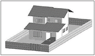
Primarily, the architectural design of the project was modeled using Revit Architecture software. This modeling is performed with the creation of project reference levels in which the program automatically generates a floor for each level. Afterwards, the two-dimensional AutoCad plants were imported, where the modeling began. In Fig. 1, can be seen an illustration of final appearance of the single-family house.
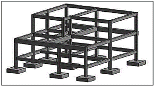
Then, the structural design was modeled in Revit Structure software. With this, it was possible to perceive the absence of incompatibilities between the architectural and structural projects. In short, this was due to the structural design being previously conceived and made compatible with the architectural design. Like this, in Fig. 2 the structural project is presented.
Subsequently, based on the sanitary design provided in AutoCad, the modeling was executed using the Revit MEP software. As Revit consists in a program that approaches BIM modeling and also provides the use of a single project model on the same platform, it was possible to carry out the modeling of the sanitary project based on the architectural and structural projects already finished. Besides that, the 3D visualization allowing many interferences to be highlighted due to the observation of the height/depth of the elements.
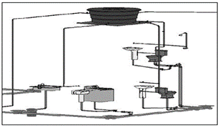
For hydrosanitary design modeling, Revit automatically connects the pipes, as long as it is configured. Tubes and connections identical to those of the original project were used, utilizing Tigre's hydrosanitary parts which already have a standardization of their models in relation to the project that is in accordance with the Brazilian standards rules. So, in Fig. 3 the hydrosanitary project is displayed.
3.3. Compatibilization projects
In possession of all the modeled projects, they were submitted to the compatibilization process. In such a manner, the models were compiled into a single file, where a common point between the projects is chosen to create the overlay. Furthermore, this file maintains a link with the original individual files, which makes it possible to carry out modifications and/or alterations with automatic updating in the compatibility model. For the evaluation and characterization of the interferences found, a compatibility matrix was produced that is showed in Table 1.
Table 1 Matrix for interferences control.
Source: Author, 2021.
The Revit also consist in a compatibility tool, which is responsible for generating a report of inconsistencies found in the project under analysis at the moment. Through this command, it’s possible to select only the specialties and/or elements which intend to be considered at that specific time. However, this report exposed a huge amount of conflicts because the program requires a perfect modeling. Thereby, it’s up to the designer involved to evaluate and filter the points of conflict most prone to incompatibilities and ignore the other interferences indicated. Professional designers know where to focus their efforts and shouldn’t waste time cleaning up the report generated by the software as this goes against BIM premises. Like this, must practice a good modeling according to the required needs [32].
3.4. Interferences found
The models of the disciplines generated were submitted to the execution of the oriented interference analysis according to the verification matrix previously exhibited. As a result, 615 errors were pointed out in the automatic report, many of which were caused by connections or elements considered unsatisfactory for the system. In this way, these errors were disregarded as they consisted of detailing errors. Finally, with the modeling performed it was possible to achieve the objective of volumetric visualization and the adequate dimensioning of the project elements.
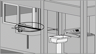
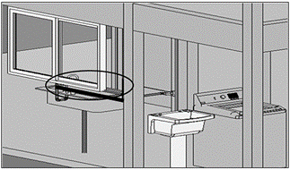
In the process of compatibilization carried out between the architectural and hydrosanitary models, a grave interference was detected. In this case, the cold-water pipe passed through a window as visualized in Fig. 4, which was classified as a high complexity interference. This fact could easily go unnoticed by the overlapping of the projects provided in AutoCad 2D due to the difficulty of spatial visualization in relation to the depth that requires considerable mental effort from the compatibilizer to understand the heights of the pipes, checking if they confront each other and/or with other elements. [23,33].
The interference happened just because the designer was decided to maintain the same height of the pipe from the service area of the 1.10 m to the kitchen that coincided with the height of the windowsill of the kitchen. This problem was solved by decreasing the height of the cold-water pipe in this region to 1.0 m as can be seen in Fig. 5.
After solving the problem, the interference report was updated and it excluded only one item from its list, totaling 614 errors. Thus, the number of errors found is small and leads to a positive evaluation of the method.
The incompatibilities generated in the other projects are due to the carelessness of the installations designers, as they would be used to making decisions on the work itself to identify the best path for the passage of the pipe. Linked to this, these adjustments can cause confrontation with the decisions of other specialties professionals, not to mention that the delay with this situation happens depending on the availability of the designers to go to the construction area, besides to works with breaks and reworks between the disciplines [34]. With BIM, this type of improvised projection will no longer exist, and the possibilities will be properly tested before the start of the execution phase.
The fact that the modeling starts from a two-dimensional perspective demands special attention in relation to certain important information that require survey. In the future, with the occurrence of direct development in softwares that contains the BIM, the provision of information will be more precise and will describe the continuous improvement of the processes. It’s believe that the project is an abstract preview of the final product. There isn’t just a single solution for each intervening found in the project. The ability to produce a complete project faster can be seen as a competitive advantage rather than developing numerous projects at the same time. The multidisciplinary and simultaneous work should be prioritized for reducing the construction period of the building [21].
3.5. Observations and discussion of results
It’s in the modeling of installations that the greatest difficulties are encountered and it’s necessary to generate numerous auxiliary cuts in the views for the insertion of the pipes in correct locations. In 3D view, the insertion of pipes is only possible in an inclined plane. Furthermore, the complexity of finding families of parts, equipments and hydrosanitary connections available for free download on the internet is highlighted, as well as for their suitability for the project. In Fig. 6, an example of an element used in the project is presented, however, incompatible with the need of project that was identified as an interference.
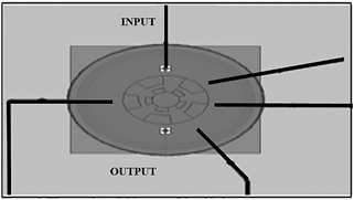
The water tank model used has two connections, but to meet the project there should be five connections. This object is an example that has at least five errors considered relevant to the program but for the purposes of this analysis performed aren’t significant. These errors are, respectively: four for lack of connections with the water tank in this chosen model and one by lack of piping installed in the remaining connection available. Thus, this case is a recurring example of incompatibilities that occurs in hydrosanitary installations. It can be said that the aforementioned conflict with the water tank is just one of the cases interpreted as a conflict in the error report generated by Revit. For that reason, these incompatibility errors were detected as object model conflicts and not as design flaws. So, this justifies the inexistence of incompatibilities found but that were registered in the program. These types of situations are found because similar elements are often used just because they are already modeled, and these are inserted on a certain occasion that doesn’t compromise the results.
It should be noted that the list of incompatibilities generated by the software can point to errors arising from failures by execution or by connection. Still, some conflicts were noticed during of the modeling. Accordingly, modeling is understood as a projection method that involves the synchrony between visualization and special analysis. By means of this, the visualization is no longer mental and becomes concrete, where any inconsistency presented cannot go unnoticed by BIM [34].
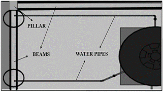
In the installation modeling stages, the largest amount of elements designed in inappropriate locations are also found, which result in interference with the reinforced concrete structure. Hence, these types of incompatibilities are characterized by pipes of water and/or sewage that pass through structural elements [35]. With this, care was taken with the cold-water pipe so that its fall occurred on the beams at a distance of at least 5 cm from the nearest face and at the same time reach a value of twice times the coverage for this same face as to its smallest dimension. As for the beam height direction, this measure must be equivalent to 1/3 of the width, at least 5 cm and also twice the face cover [31]. On that account, as the smallest dimension of the beam is 15 cm, the pipe was positioned right in the middle of this measure, as can see in Fig. 7.
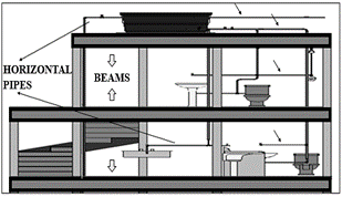
Also, it’s worth noting that the cold-water pipe didn’t pass horizontally inside the beams as shown in Fig. 8.
Regarding the sewage pipes, it passed vertically through the slab to connect the toilets and the bathrooms sinks on both floors, respecting the limit parameters as shown in Fig. 9.
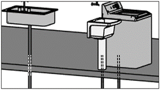
The sewage pipes was also responsible for making vertical holes in the slabs at the connections of the sinks and of the washing machine, as indicate in Fig. 10. All pipes obeyed in the standard referring to the making of holes and openings in structural elements [31].
Throughout the images obtained, can clearly perceive the dimensional and spatial difference provided by Revit in relation to the representation of projects in AutoCad 2D. This is all due to the parametric capability of one compared to the limited geometric capacity of the other. One of the great advantages of BIM is the automatic reproduction of sections and views across the exclusive realization of the floor plan of any type of building. What’s more, the automatic alterations of changes generated at a specific point in the projects are instantly reflected in other projections. So, it’s evident the significant reduction of time spent with the reworking of projects as occurs in AutoCad program.
The aim of the methodology presented here was to meet any type of construction, despite having concentrated the case study on a reinforced concrete building. It’s noteworthy that as bigger size of the building as greater the benefits obtained with the adoption of BIM due to the quantitative of existing projects for compatilizations processes. Further, prefabricated systems are greatly benefited by the possibility of repairing to the elements, avoiding the loss of the part and its remanufacturing on account of the lack of fitting.
It was understood that for the efficient development of a project is essential that the entire projection is carried out mutually, with the analysis of all the suggestions and proposals of each member in relation to their respective profissional area in search for the best adaptation from the model to the final product. From this, along an architectural conceptation idealized initially must be dimensioned the projects of necessary installations indicating the holes for the passage of pipes and conduits. Finally, these projections must be passed on to the structural designer, so that he will evaluate all the observations made and will seek to fully meet the requirements raised or will suggest some changes for debate among all those involved. This chain cycle should occur until all the participants are in agreement with all the project measures established to advance to the execution stage.
Revit is the most used software with a BIM interface on the sector of the projects and that has a good requirement in terms of interoperability [23]. This program comes from a platform that is composed of several others compatible softwares with the same characteristic identity, which provides file sharing and information exchange within this surface by the different programs involved.
4. Note from other authors
In this section, the interferences identified by others authors in cases studies of others projects were cited and the constatations obtained. Besides, there are others BIM interfaces softwares were utilized that contribute to the developmente of a quality project and which are as powerful as Revit. Based on this, a comparison was made between the incompatibilities identified by them with the case study discussed in this article.
4.1. Marsico et al., 2017
In this research, the prediction of pillars wasn’t initially performed in the project analized, which caused them to overlap with the walls. Consequently, that resulted in the formation of interferences in the corners of the doors and the openings of the windows frames. To correct this problem, was necessary to adjust the length of some windows and doors to suit the space. This incompatibility demonstrated that BIM offer an economic advantage because the failures would generate the purchase of elements couldn’t be used [35].
BIM was developed by construction methods of foreign standards. By this the software ends up identifying certain anomalies in practices that are commonly carried out in Brazilian constructions, for example, a conduit or pipe passing inside walls and/or by structural elements, according to Figs. 7, 9 and 10 of this article. In view of this, the situations observed are usual, since foressen in structural projects. Otherwise, can generate a reduction in strength of element and non-conformities in assembly of forms [35].
Thereby, the authors too found in their investigation an interference similar to the one shown in Fig. 4 of this article. Furthermore, others problems were found that consisted of pipelines from the hydrosanitary project crossing each other what in 2D are hardly to see because they’re represented in the same horizontal plane [35].
4.2. Callegari, 2007
In her survey, an interference between the beam and the window was identified. The problem could be easily solved with the reduction of the sill height of the chosen window or by replacement by other window equivalent to the available space or yet with the elevation of beam by increasing the room's high. This type of inconsistency was quickly noticeable by BIM while in a 2D view this factor could go unnoticed depending on the professional's attention at the time of compatibilization [20].
4.3. Costa, 2013
The interference report in your research identified an interference between the largest cable tray of the project under analysis and the beam. So, this problem was taken to the executive process for decision making to how solve it. It is noteworthy, that the execution of holes and openings in the structural elements must be analyzed on a case-by-case basis by designer project [36].
4.4. Mikaldo Júnior, 2006
The author cited in his interpretation inquiry, how the 3D visualization of BIM’s important to be able to distinguish everything that is happening in project. His noted that the integrated view of 3D models supports the adoption of the most measure adequate for the preservation of quality required by product final [33].
4.5. Goes, 2011
The case study presented in his evaluation proved that the compatibilization process carried out in BIM detected 75% more interferences than the conventional method. Many of the design problems detected were associated with insufficient datas and details provided by the projects in AutoCad 2D. Also exposed one of the major problems that occur in the 2D design of hydrosanitary projects, when they are dimensioned without taking into account the angulation of connections pieces for fitting. As soon, the position of the elements had to be changed for adapting to reality. With BIM this problem can be avoided by using exactly the parts modeled with their real existing dimensions and inclination angles [34].
4.6. Manning e Messner, 2008
The case analyzed as a contribution to the theme exposured the main advantage of the BIM, that the instantaneous 3D visualization of the project and the possible alternatives of how the hospital equipments would be positioned for a better use the spaces. Thus, numerous setbacks marked delays in the evolution of projects because they were starting from the available projects in AutoCad 2D. Therefore, this process caused difficulty for interested parties to understand and imagining to what could be the design final of the project. Subsequently, the project was modeled and the continuation of its feasibility and execution carried out in Revit. The benefits found were: reduced design time, increased level of construction details, efficient parameterization, easier conversion of metric units, adaptable work to geographic distance, saving efforts and reducing costs [37].
5. Final considerations
Taking into account the arguments presented, based on the case study discussed and what has already been presented in other studies, was highlighted that is necessary to have a transition in the process of project compatibility in relation to the methods used under a perspective restricted to a 2D analysis. It’s essential that everyone aware that the BIM methodology came to fill the visualization deficiency with it’s 3D notion of what’s really happening in the project.
It’s noteworthy, that the main characteristics of BIM that stand out is the parameterization of information, allowing automatic and instantaneous updating throughout the project and the existence of a single file for compiling all project datas. It’s related that many of the problems were caused due to the faulty management at the time of the information feedback being totally dependent on the designer in the conventionally employed practices and also because there were numerous different files for the same project. Therefore, the most recent BIM technological innovation emerged due to the deficit in quality and productivity registered in works constructions around the world. In consequence, were reduced rework, material waste, construction schedule time, construction problems and the cost of projects.
For all that, BIM arrived in the civil construction sector to revolutionize the way of designing and executing projects. This is because the system with simulation potential provides the virtual construction of the building in an identical way to the real construction mode, thus presenting, throughout the evolution, the points of interference between the means for decision making on the appropriate measure, adapting the project to each identified barrier highlighting the reliability of the compatibility.
It should be noted that BIM rescues the need for collaboration, communication and integration between the professionals involved and affirms their essentiality for each project to be conceived, making them safer, more reliable and consistent with all the different specificities involved. It’s also understood that, while BIM promotes the control of the design and execution phases, it allows a considerable increase in the efficiency of entire production chain.
It’s reported that the modeling processes of the architectural and structural projects were smooth as they were generated in fast and repetitive processes, with a low level of detail. The sanitary project, on the other hand, required time due to the low processing capacity of the machine used, as well as the high level of detail of the parts, elements and connections, which end up overloading the computer, causing delays in updates and frequent waiting time intervals for the reproduction of the modifications.
6. Conclusions
Finally, the proposed objective was achieved by the incompatibilities found that contributed positively to the final result. The Revit is a BIM software capable of detecting interferences between projects and contributing to decision making. This methodology has a lot to add to the civil construction sector as long as all professionals are able to use the system. Also, given the unique character of each building, can see that the problems encountered are almost always the same, but that vary in proportion.
In essence, known that still a long way to go, but this concept of building information modeling’s disseminated in each research carried out. In short, is essential that more time is required for the development of the project so that during execution, problems which impact the schedule that could compromise the result and the quality of the project don’t arise. Therefore, the practice of project compatibility consists in the constant search for updating the best version for the project in order to avoid financial and temporary inconveniences.
The Revit software is an efficient and collaborative tool in relation to the practice of projects compatibility. This system has shown that is capable of reducing design errors that were propagated to execution. Overall, the best way to project is based on the architectural concept, carrying out on this sketch the projects of complementary installations and in the end, the structural dimensioning.


