


 English (pdf)
 Article in xml format
 Article references
 Send this article by e-mail
 Cited by SciELO
  Cited by Google
  Similars in
SciELO
Similars in
SciELO  Similars in Google
 Permalink
1. Introduction
Impact or vibratory loads produce undesirable effects on mechanical systems and their components. They can lead to local deformations, structural failure, etc. The dynamic response of a structure depends on its mechanical characteristics and the nature of the induced excitation [1].
The inhibition of the negative effect of impact or vibratory loads is obtained by implementing control techniques [2], for that reason, various energy dissipation devices, such as active, semi-active and passive devices, are being applied worldwide [3].
Passive systems rely on various forms of energy dissipation, such as friction, viscoelasticity and plastic deformation. Factors such as geometry, material properties and magnitude of the force being subjected are of relevance to the analysis of passive shock absorption systems. A passive control does not require input energy for its operation, and its energy dissipation system is based solely on mechanical systems or the material's own damping [4].
The incorporation of passive energy dissipation devices in a structure is to absorb a significant percentage of the incoming energy to the system, reducing potential structural damage and strength degradation [5].
One of the main advantages of passive friction systems is the high energy dissipation capacity per cycle, and it is possible to control the required friction force prior to its use [6].
The trend in the study of passive energy dissipaters is presented in Fig. 1, which illustrates the growth of passive friction system studies since they were introduced in civil engineering four decades ago [3].
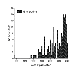
Source: Jaisee et al., 2021.
Figure 1 Graphical representation of the number of publications reviewed versus the year of study
The principle of operation of passive friction systems is based on the dissipation of energy from the relative motion between two bodies. This concept has inspired the design of friction devices, such as the leaf spring and the pioneering Pall friction damper [7].
In the literature there is information on the evolution of passive friction dissipators, due to the fact that there are continuous improvements on the same dissipators or new proposals due to the different needs that appear in structural engineering.
Dissipators such as the PFD [7] and the SBC [8], whose main features are the implementation of bolted plates with sliding for energy dissipation by friction. The SFD [9] and EDR [10], which use wedges to generate friction and springs for the application of preload.
In addition to the dissipators mentioned above, there have been other devices such as the AFD [11], the multiple friction damper (MFD) [12], the friction wall damper (FWD) [13], the SCFD [14], which stands out for its self-centering feature, and the STFD, whose novelty is the implementation of a tubular steel structure [15].
In most of the designs mentioned above, the preload is applied by means of springs or bolts, with which the friction force is defined. The objective of the present work is to propose a passive friction dissipator for the mitigation of cyclic loads in structural engineering, using as structure layered elements, without the use of springs or bolts for the application of the preload. The design is based on the layer friction damper (LFD) [16].
2. Designs of the energy dissipator
2.1. Energy dissipator
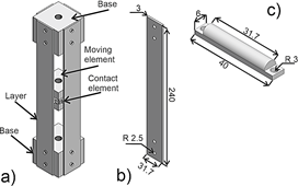
In this work, a variation of the LFD proposed by Dominguez [8] is proposed. The dissipator consists of friction layers, friction elements, two bases and a moving element. Fig. 2 (a) illustrates a schematic of the dissipator, which consists of 4 layer elements. The friction elements are fixed by bolts, and the friction layers are fixed to the bases by bolts. Fig. 2 (b) shows the dimensions of the layer element, while Fig. 2 (c) shows the dimensions of the contact element [8].
2.2. Cyclical numerical test
The development of the discrete model was performed in Abaqus software; the aluminum layer was modeled as a Shell type deformable material (S4R) [17], while, the contact element is considered aluminum as a solid type deformable material (C3D8R). In process of the interactions, a friction coefficient of 𝜇=0.36 [18] between the contact surfaces (Surface to Surface) was used. The layer was considered to have a length of 240 mm, having 40 mm per end as the embedment length. The discrete model and dimensions of the contact element are shown in Fig. 3. The properties of 6061 aluminum are presented in Table 1.
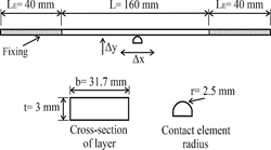
Table 1 Mechanical properties of 6061 aluminum
| Density [ 𝐠 𝐦 𝟑 ] | Young modulus [MPa] | Yield stress [MPa] | Poisson coeficient |
|---|---|---|---|
| 2.7 | 69000 | 275 | 0.33 |
Source: Akram et al., 2018.
The numerical model consists of four stages; in the first stage, the system is preloaded by deforming the beam by displacing each of the contact elements (0.8 mm); the second stage defines the movement of the contact elements along the length of the beam (40 mm); the third stage corresponds to the displacement in the opposite direction to the second stage, and finally, the contact element returns to the initial position, as shown in Fig. 4.
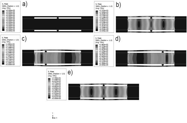
Source: Prepared by the authors.
Figure 4 Numerical simulation stages, where: a) initial position, b) preloaded system, c) total displacement to the left, d) total displacement to the right and e) return to initial position
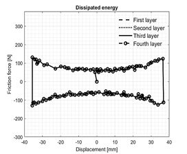
The model contemplates four layer elements in the energy dissipator, the comparative analysis of the energy dissipation provided by each of the layers is shown in Fig. 5.
Source: Prepared by the authors.
Figure 5 Comparison of numerical results for each of the disipator's layers.
The amount of energy dissipated by each of the layers was calculated by obtaining the area contained in the force-displacement graph. The results obtained numerically show that each of the layers provides the same amount of energy dissipation, i.e., the system behaves symmetrically, with each of the layers dissipating approximately 13 J, i.e., the system dissipates 52 J. This allows us to consider the modeling of only one layer element for subsequent analyses.
2.3. Effect of preload on system
Fig. 6 shows the effect of the initial preload of the dissipator on the hysteretic behavior of the dissipator. Fig. 6 shows that the energy dissipation in one cycle of the dissipator is higher with respect to the initial preload.
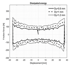
Table 2 shows the energy dissipation results of the system with respect to the initial preload. It shows that by increasing the preload by 0.2 mm, i.e. from 0.8 to 1 mm, the energy dissipated increases by approximately 34.7%, while with 1.2 mm of preload, the energy dissipation increases by 67%, with respect to the dissipation with 0.8 mm. The results shown in Table 2 represent the energy dissipated per dissipator layer.
2.4. Layer stacking effect
The stacking of layers is mainly used in leaf springs or flat springs, whose main based is to dissipate energy by elastic deformation and dry friction [20].
Spotts [21] assumes that as long as the layers maintain contact with each other along their entire length, the actual spring shown in Fig. 7 (a) can be replaced by the trapezoid in Fig. 7 (b).
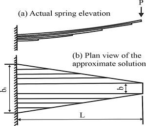
To form the trapezoid, it is assumed for each of the stacked layers a cut along its center and each half placed on the sides of the longest layer.
The purpose of stacking the layers is to increase the bending stiffness of the system, which causes an increase in the frictional force, thus also in the energy dissipation capacity of the dissipator.
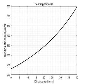
The bending stiffness for the case of a layer or beam fixed at both ends is given by the following expression:
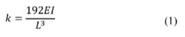
Where:
𝑘 |
= Flexural stiffness |
𝐸 |
= Elasticity modulus |
𝐼 |
= Second momento of area |
𝐿 |
= Layer length |
𝑥 |
= System displacement |
𝑘 |
= Flexural stiffness |
Fig. 8 shows the variation of the stiffness of the layer, this with respect to the allowed displacement, for the case of one layer.
For the case of stacking layer elements, a factor K 1 [21] is used, which depends on the ratio between the widths of the stacked layers b/b0. The moment of inertia I0 refers to the section and is equal to (b0 h3)⁄12, where h is the thickness of the layer. Fig. 9 shows the increase in bending stiffness considering stacking of layers.
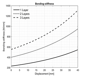
The bending stiffness considering a second stacked layer (of the same dimensions) increases by approximately 74% with respect to the stiffness of a layer element, while, using a third layer, the stiffness increases by approximately 139%, i.e. proportional to the number of layers used.
Fig. 10 shows the scheme and boundary conditions of the stacking of layers contemplating 3 elements.
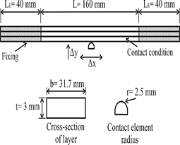
Fig. 11 shows the effect of friction sheet stacking on the hysteretic behavior of the dissipator, considering three cases, the first, using only one layer, the second, having a second layer stacked, and the third, stacking a third layer.
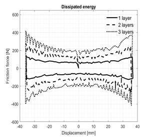
Table 3 shows the energy dissipation results of the system with respect to the stacking of layers. It shows that, by increasing the number of stacked layers, the energy dissipation capacity increases, i.e., by adding a second stacked layer, the energy dissipation capacity increases by approximately 100%, while, by stacking a third layer, the energy dissipation increases by 200%, with respect to the dissipation with only one-layer element. The results shown in Table 3 represent the energy dissipated per dissipator layer.
3. Conclusions
In the present investigation, the study of a proposed LFD variation was carried out. Numerical tests were performed, analyzing the effects of the initial preload on the dissipator and the stacking of the layers. From this, the following was determined:
The LFD dissipates 11J of energy with a four-layer configuration (one per side), whereas, the proposed dissipator has the capacity to dissipate approximately 52 J, i.e., more than four times that allowed by the LFD.
Increasing the initial preload on the dissipator, increases the energy dissipation capacity, this considering only the elastic range of the proposed dissipator.
The flexural stiffness of the layer elements increases proportionally to the number of layers used.
The stacking of layers allows the increase of the operating range of the dissipator, being a proportional increase for each of the stacked layers.
The dissipator is applicable for different operating ranges, this according to the user's need.
The results obtained from the analysis of the proposed energy dissipator design show its functionality under cyclic loads. The prototype represents an alternative to the energy dissipators currently existing in structural engineering, with the characteristic of not needing external elements such as bolts or springs to perform the preload. The use of beams as a structure allows the application of the preload through its deformation. The design allows to scale or increase the range of dissipation capacity by stacking the elements of the layer, expanding the possible applications.
The proposal has as an additional feature a simple design, easy to manufacture and assemble.

