


 Inglés (pdf)
 Articulo en XML
 Referencias del artículo
 Enviar articulo por email
 Citado por SciELO
  Citado por Google
  Similares en
SciELO
Similares en
SciELO  Similares en Google
 Permalink
1. Introduction
Micropiles are deep foundation elements, with a final diameter no higher than 300 mm (regardless of the presence of reinforcement in its composition), that are drilled and grouted [1]. They were first conceived by Lizzi, in Italy, during the 1950s, period in which he applied for the first patents under the designation of “pali radice”. The initial idea was to produce a foundation complex of small piles inclined in various directions, like the root system of a tree, and was first used as structural underpinning for buildings affected by post-war effects [2]. However, the micropile technology was disseminated worldwide only in the 1980s, after the patent completion, when several companies started to develop their own procedure methodologies that receive different designations, such as pin piles, root piles, hollow bar micropiles etc. According to the Federal Highway Administration (FHWA) [1], micropiles can be classified based on their grouting methodology as follows: type A, in which grout is poured inside the pile only by gravity, with no injection pressure; type B, in which grout is poured, by gravity, inside the pile after which injection pressure, between 0.5 and 1.0 MPa, is applied at the head of micropile as the drilling case is pulled out; type C, in which grout is initially placed by gravity and injection pressure is applied between 1.0 and 2.0 Mpa and, before its hardening, a second batch of grout is injected into predetermined depths, creating bulbs in these regions; and type D, similar to type C, but with modifications in the second injection stage where grout is injected under pressures between 2.0 and 8.0 Mpa only after the first grout batch has completely hardened, a process which can be repeated as many times as necessary, respecting the curing time between stages. Types C and D are also called post-grouted micropiles. Nowadays, given their diversity, grouted micropiles have their applications in several fields of civil construction, especially those in which they are laterally top-loaded, a field with little published data in recent years [3-10].
Horizontally top-loaded piles are recurrent in construction works and, usually, these horizontal loads act simultaneously with vertical loads and bending moments, most frequently in buildings under wind action, transmission towers, wind turbines, bridges, viaducts, retaining walls under active earth pressure, excavations for building basements etc. These conditions are aggravated in saturated environment, especially in porous and collapsible soils, which can present an apparent high resistance under unsaturated conditions that vanishes almost completely in the presence of water, resulting in large displacement rates [11]. It is also known that, in these cases, the foundation behavior is mainly controlled by the surface layers of the terrain, where the structural elements are embedded.
In Brazil, the presence of colluvial, porous and collapsible soils in small depths below ground surface is high. Over the last few decades, several studies have been conducted to investigate the behavior under lateral loading of different pile types installed in residual lateritic diabase soil typical from the city of Campinas, state of São Paulo, Brazil. The first study was carried out by Carvalho et al. [12], in which a 14 m length and 0.18 m diameter precast concrete pile was installed in an experimental field at the Faculty of Agricultural Engineering (Faculdade de Engenharia Agrícola - FEAGRI) of the University of Campinas (Universidade Estadual de Campinas - UNICAMP) and transversally top-load tested. At the same site, Miranda Junior [13] studied the horizontal behavior of 4 bored, 4 continuous flight auger (CFA), 3 root, and 3 full displacement (FD) piles, all with lengths of 12 m and diameters of 0.40 m, with exception of the FD piles whose diameters were 0.37 m. The tests performed by Miranda Junior [13] were done in two situations: natural soil condition and soil excavated 1 m around pile head and replaced by compacted soil-cement. In the next year, Zammataro [14] evaluated the behavior of 3 bored and 3 CFA piles at the same site, all also with 12 m lengths and 0.4 m diameters. Posteriorly, Miguel et al. [15] tested two TR37 section steel-rail anchor piles at the respective field, one with a single section and the other with a double section and lengths of 12 and 18 m, respectively. Kassouf et al. [16] and Albuquerque et al. [17] studied the behavior of a belled caisson with 0.8 m in diameter, 9 m in depth, and 1.6 m in base diameter at the experimental site. Lastly, Albuquerque et al. [17] also presented the results for a CFA pile and a bored pile, both with 12 m length and 0.40 m diameter, and a steel pile with the same length. Excepting the study by Zammataro [14] and some cases of Miranda Junior [13], all tests mentioned previously were performed in natural soil moisture condition and after its full saturation, i.e., less favorable situation for the respective soil profile.
Unlike the piles that are solicited by tensile and compressive loads, the geotechnical rupture load of horizontally loaded piles is hard to be assessed. For this reason, the design process for these pile types is not related to an ultimate lateral load, but rather to a maximum or predetermined movement that can be attained [18]. Furthermore, due to the extremely complex problem of modeling the horizontal action, which is tridimensional, simplified and classical mathematical models are commonly employed for these cases [18-23]. The most common concept used for dimensioning piles under horizontal loadings (and bending moments) is the one proposed by Winkler based on the theory of horizontal reaction of the soil, where its behavior is modeled as a set of independent, equal, and evenly spaced springs, i.e., its reaction is linearly proportional to the displacement in any analyzed point along depth. With this hypothesis, Terzaghi [24] was the first to present the modulus of horizontal reaction as a relation between the applied force and its respective displacement, as follows in eq. (1):
in which K is the modulus of horizontal reaction, p is the pressure applied at the pile head and y is the horizontal movement. Since this equation is independent of the pile diameter, it can be rewritten as defined in eq. (2) below:
where kh is the horizontal reaction coefficient and D the pile diameter. For over-consolidated clays, Terzaghi [24] stated that this relation is constant along depth whereas, for normally consolidated clays and cohesionless soils, the author proved to be approximately linearly below ground surface according to eq. (3):
in which nh is the modulus of the soil horizontal reaction and z is the depth below ground surface. Alizadeh and Davisson [22] presented the first empirical study regarding the variation of horizontal reaction coefficient nh along pile length. The authors compared the horizontal displacement at the pile head from load tests with the values obtained from eq. (4), proposed by Matlock and Reese [19,20]:
where y0 is the horizontal movement at the pile head, H is the lateral load applied, T is the relative stiffness between the pile and the soil, E is the pile elasticity modulus, I is the moment of inertia of the pile cross-section, and Δy is the correction of the lateral displacement. The relative stiffness T is given by eq. (5):
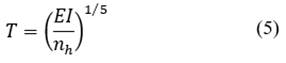
and the modulus of the horizontal reaction nh defined according to eq. (6):
Considering the little available information in the literature concerning about horizontally top-loaded micropiles and the lack of data on these foundation elements under this loading type in highly porous, collapsible, and lateritic soil, the present study aims to provide design parameters and to investigate the performance of four transversal load tests in a new post-grouted micropile configuration, with the soil at its natural moisture content and after-flooding. Based on the lateral loading tests, the effects of soil saturation on the load-displacement curve and on the horizontal reaction coefficient were verified, and their results were compared with those obtained for other pile types in the same geological-geotechnical context [12-17]. The results from lateral top-load movement curves were related based on the average loads to shift the pile head in 6 and 12 mm, and the design parameters were based on the average value in the range between these values [13,14,21].
2. Materials and methods
To investigate the behavior of this new type of micropile, a new testing site was set up at FEAGRI, UNICAMP. This new facility provided supplementary characterization to the local subsoil in addition to other works carried out in two other experimental fields at UNICAMP and extensively evaluated in recent bibliographies [12-17,25-29]. The main geological and geotechnical characteristics of the new experimental field, the new post-grouted micropile installation process and the loading test assemblage and procedure are presented below.
2.1. Geotechnical site conditions
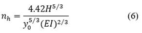
The new experimental site was located at the FEAGRI - UNICAMP. For site stratigraphy characterization, two Piezocone Penetration Tests (CPTu) and five Standard Penetration Tests with torque measurements (SPT-T) were performed. The tests and mean values from SPT-T and CPTu tests are shown in Fig.1 - in gray and black lines, respectively - in which qt is the corrected cone tip resistance, fs is the cone skin friction, NSPT,60 is the N value from SPT test with 60 % energy, and Tmáx is the maximum torque. Both in-situ tests indicate a subsoil profile composed as follows: a first layer of colluvium formed by silty clay from the ground surface down to 5m depth, followed by a diabase residual soil constituted by silty clay to clay down to 20 m. Also, lateritic concretion lenses were found from 5 m to 7 m, and water table level was found around 17 m. In general, the subsoil profile turned out to be very similar to the other two experimental fields at UNICAMP, as demonstrated in previous studies [12-17,25-29].
A series of laboratory tests were carried out for each meter from disturbed soil samples collected from SPT-T tests. Table 1 shows the results for Plastic Limit (PL), Liquid Limit (LL), Plasticity Index (PI), Water Content (w), Specific Gravity (Gs), and Casagrande’s classification for plasticity of fine-grained soils (USCS). Overall, the information obtained from CPTu and SPT-T tests, regarding soil type and resistance parameters in unsaturated conditions, allows to state that the soil in the new experimental field is of low resistance and most likely of high collapsibility, in accordance with the other two testing sites [25,29].
Table 1 Laboratory tests results from SPT-T soil samples.
| Depth | PL (%) | LL (%) | PI (%) | W (%) | Gs (g/cm³) | USCS |
|---|---|---|---|---|---|---|
| 1 | 35 | 51 | 16 | 31 | 3.03 | Low Plasticity Silt (ML) |
| 2 | 36 | 46 | 10 | 30 | 2.97 | |
| 3 | 37 | 49 | 12 | 30 | 3.01 | |
| 4 | 37 | 48 | 11 | 30 | 3.07 | |
| 5 | 35 | 43 | 8 | 30 | - | |
| 6 | 39 | 46 | 7 | 37 | 3.07 | |
| 7 | 45 | 55 | 10 | 40 | 2.97 | High Plasticity Silt (MH) |
| 8 | 47 | 58 | 11 | 42 | 3.01 | |
| 9 | 48 | 60 | 12 | 40 | 3.07 | |
| 10 | 50 | 58 | 8 | 43 | 3.07 | |
| 11 | 45 | 59 | 14 | 46 | - | |
| 12 | 44 | 55 | 11 | 47 | 3.02 | |
| 13 | 45 | 53 | 8 | 46 | - | |
| 14 | 44 | 58 | 14 | 47 | 3.12 | |
| 15 | 42 | 56 | 14 | 45 | - | |
| 16 | 40 | 59 | 19 | 44 | 3.07 | |
| 17 | 39 | 57 | 18 | 47 | - |
Source: The authors.
2.2. Installation of the new post-grouted micropiles
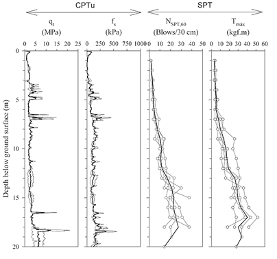
The novelty regarding the new post-grouted micropile lies on the use of a special type of casing tube that performs four main functions: pile structural component, resistant equipment for drilling and water circulation, neat cement injection in the pile tip, and local neat cement injection along pile shaft. The structural capacity of this micropile type is assured by its casing tube, composed of several steel pipe sections made of N-80 class steel with yielding strengths, in compression and in tension, of 655 MPa and 689 MPa, respectively. Each section has an inner diameter of 8 in (200 mm), thickness of 8.2 mm, and length of 2.5 m, of which the ends are thread able to connect male and female joints. The first tube section also has a crown in one end, responsible for the drilling process. For grout injection along pile shaft, the steel pipe sections contain a system of four diametrically opposed valves spaced 0.5 m apart along their length. These valves are made of an aluminum body and a rubber packer that opens with an injection pressure around 2.0 MPa and, after the pressure is unfastened, automatically closes, avoiding reflux of neat cement grout and/or loose soil back into the tube. The full procedure for its installation is given as follows:
Soil is drilled down to the design depth by roto-percussion with the casing tube and water circulation inside. The perforation and water circulation are suspended every time the top of the tube section reaches the ground surface level, when other section is then attached to it. In case of very resistant bearing stratum, eccentric bits with Widia components can be connected through rods, inside the casing tube, down to the stratum level to weaken the resistant soil layer by roto-percussion with water, allowing the resumption of the casing tube advance. In this study, this technique was applied for lateritic concretions lenses around 7 m deep and resistant ground stratum at great depths;
Once the design depth is reached, a single packer is inserted inside the steel pipe down to the bottom of the excavation to start the global injection stage. By the support of a hydraulic pump, the packer is then inflated, and neat cement grout is injected with pressures around 2.0 MPa. Thus, any loose material at the pile tip is washed away by upward flow through the gap formed between casing tube wall and adjacent soil during the drilling process. The flow is maintained until no apparent loose soil particle be seen at the top of the micropile;
At least 12 hours after the global injection phase, the post-grouting injection phase begins. For this, a double packer is positioned inside the casing tube at predetermined depths according to the design specifications, so that the depth to be injected is between the two packers. During this stage, it is expected that pressure increase until a peak value to open the valve, followed by a residual pressure enough to keep the valve system opened. The grout must be injected according to design specifications or until there is a considerable increase in pressure at the hydraulic pump, i.e., the valves have closed. This process must be made from bottom to top and can be repeated multiple times, respecting the curing time of the neat cement between post-phase injections;
Lastly, the interior of the casing tube is filled with gravity-poured grout.
Fig. 2 shows the lost structural drilling casing used in the new micropile configuration, highlighting the valve operation under pressure. Fig. 3 shows the drilling, global injection, and post-grouting injection phases previously described. According to the micropile classification given by the FHWA [1], this new configuration is classified as a type D. The micropile executed for this work had a total length of 17 m and a final diameter (borehole drilling diameter) of 0.30 m. Moreover, a single post-grout phase injection was performed for this micropile. Table 2 shows the main aspects of its grouting operation.
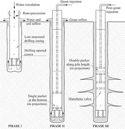
Table 2 Main aspects for grouting and post-grouting operations.
| Operation Aspects | Quantity |
|---|---|
| Total number of valves along the shaft | 34 |
| Global injection cement quantity (kg) | 1200 |
| Average injection pressure in global injection (MPa) | 2.0 |
| Post-grouting injection cement quantity (kg) | 1700 |
| Number of valves that opened in the post-grout stage | 15 |
| Shaft segments in which the valves opened (m) | 5.0 - 8.0; 10.0 - 11.5; 13.0; 14.0; 14.5; 16 |
| Average grout pressure to open the valves (MPa) | 2.3 |
| Average residual grout pressure to keep the valves open (MPa) | 1.7 |
| Water cement ratio for grouts in both injection stages | 0.5 |
| Amount of cement for grout poured by gravity (kg) | 600 |
Source: The authors.
2.3. Horizontal load tests
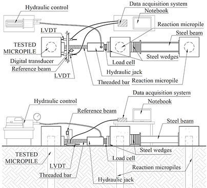
The reaction system for the horizontal load test consisted of two other micropiles with final diameter (borehole drilling diameter) of 30 cm and length of 17 m. Before the load tests, 60 x 60 x 60 cm pile caps were built on the top of the three micropiles. In the field, both reaction micropiles were connected through steel wedges and a steel beam. For load
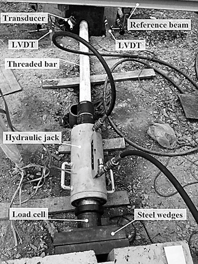
application, a hydraulic system composed of a cylindrical hydraulic jack with ultimate capacity of 500 kN plugged in a hydraulic pump was used. A threaded bar and steel wedges were used to connect the tested and the reaction micropiles. A 500 kN load cell was employed to determine the load applied by the hydraulic system and, for the measurement of displacements, two Linear Variable Differential Transformer (LVDT) were attached to a reference beam and horizontally positioned at the tested micropile cap. A third point of displacement measurements was taken at the center of the tested micropile cap for real-time reading. The data from load cell and LVDTs were obtained via a data acquisition system named HBM QuantumX Assistant 840 and converted in load and displacements values by Catman Easy, a data reading software. Fig. 4 shows the horizontal load test configuration. Fig. 5 shows in-situ details about the equipments between tested micropile and reaction system.
A total of four horizontal load tests were performed in the tested micropile: the first two were conducted with the soil in its natural moisture content state, followed by the other two being conducted after the superficial soil was continuously flooded for 72 h, all in accordance with the Brazilian standard [30]. Since the most critical state in lateral loaded piles happens rapidly, e.g., under fast solicitations from variable loads, the quick loading test was preferred over the slow maintained one because it better represents the work situation [8,11,13]. The quick loading horizontal test consists as follows: (1) the load must be applied in successive stages with values equal or lesser than 10 % of the predicted working load and maintained for 10 min, independently the settlement stabilization having been reached; (2) each stage displacement must be measured and noted after 1 and 10 min from load application; (3) at the last loading stage (twice the working load), the maximum load must be held for 2 h before the unloading stages begin and movement readings must be made after 10, 30, 60, 90, and 120 min from load application; (4) the unloading must be carried out in at least four stages in relation to the maximum load reached, and horizontal displacement readings must be done after 1 and 10 min from loading relief; (5) at the last unloading stage, the load must be maintained for 1 hour and movement measures must be read at 30 and 60 min. All the four tests were carried out with load increments of 5 kN.
3. Results and analysis
3.1. Load-displacement responses
Figure 6 shows the load-displacement curves obtained from the transversal loading tests. The first test under natural conditions of soil moisture had to be interrupted abruptly because the threaded bar, responsible for transmitting the load from the hydraulic jack to the pile head, went out of alignment at 75 kN and total displacement of 14.86 mm. For the second test under this condition, the pile tended toward the geotechnical failure after the initial linear behavior up to the 75 kN load. The test was declared finished at the load of 85 kN, corresponding to the lateral movement of 40.41 mm. Regarding the flooded condition, both tests showed first displacement values considerably higher when compared to the natural situation, which can be explained by the fact that the pile was loaded twice before the flooded test. Conversely, this condition presented similar behavior with the natural one with linear trend up to the load of 75 kN followed by sudden increase in displacement. This similar performance is because the grout injection phases were able to recover the matrix potential of the collapsible soil, which had been lost due to the excavation with water circulation. First and second loading tests after full saturation were declared finished at the loads of 85 and 90 kN, with a total lateral displacement of 48.45 and 42.28 mm, respectively.
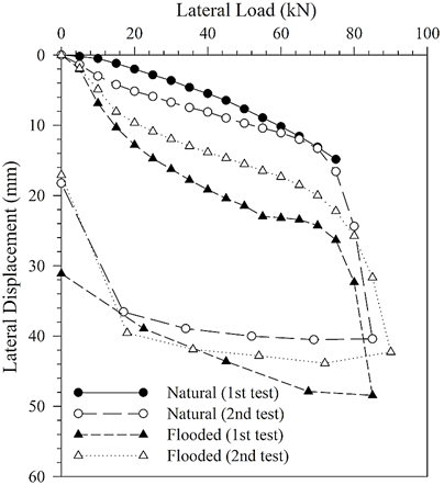
Table 3 shows the load necessary to reach displacements of 6 and 12 mm for both conditions and the ratio between them for the new procedure of post-grouted micropile as well as for previous studies carried out in the same subsoil profile [12-17]. Although the load required to displace 6 and 12 mm under natural moisture conditions is one of the smallest for the micropile case, the same is not observed under flooded conditions, where the loads are only smaller when compared to the cases treated with soil-cement. Notably, the performance of micropiles under these conditions was better even when compared to piles with water circulation during drilling followed by grouting, such as root and continuous flight auger piles without soil-cement treatment, showing greater potential for treating the respective collapsible soil.
Table 3 Horizontal loads (H), in kN, to shift the pile head in 6 and 12 mm and comparison between conditions.
| Pile | Natural | Flooded | Ratio between H for 6 mm | Ratio between H for 12 mm | ||
|---|---|---|---|---|---|---|
| H for 6 mm | H for 12 mm | H for 6 mm | H for 12 mm | |||
| Bored [17] | 50.3 | * | 6.8 | 12.0 | 7.4 | - |
| Bored 3 [13] | 46.3 | 48.3 | 4.2 | 6.9 | 11.0 | 7.0 |
| Bored 4 sc [13] | 89.9 | 101 | 30.2 | 59.4 | 3.0 | 1.7 |
| Caisson [16] | 135 | 165 | 47 | 62 | 2.9 | 2.7 |
| CFA [17] | 46.1 | 55.9 | 4.0 | 7.8 | 11.5 | 7.2 |
| CFA 3 [13] | 55.1 | 57.1 | 7.6 | 12.1 | 7.3 | 4.7 |
| CFA 4 sc [13] | 110 | 146 | 17.5 | 33.0 | 6.3 | 4.4 |
| FD 3 [13] | 130 | 180 | 13.1 | * | 9.9 | - |
| FD 1 sc [13] | 106 | 135 | 43.1 | 78.9 | 2.5 | 1.7 |
| FD 2 sc [13] | 166 | 201 | 46.7 | 127 | 3.6 | 1.6 |
| Precast [12] | 13.0 | 18.5 | 3.4 | 6.5 | 3.8 | 2.8 |
| Root 3 [13] | 120 | 175 | 8.8 | 12.0 | 13.6 | 14.6 |
| Root 1 sc [13] | 131 | 157 | 17.2 | 40.4 | 7.6 | 3.9 |
| Root 2 sc [13] | 98.7 | 122 | 35.5 | 95.2 | 2.8 | 1.3 |
| SR SS [15] | 15.0 | 20.5 | 0.6 | 1.1 | 25.0 | 18.6 |
| SR DS [15] | 5.6 | 10.0 | 2.9 | 6.0 | 1.9 | 1.7 |
| Steel [17] | 52.7 | 69.5 | 6.8 | 11.8 | 7.8 | 5.9 |
| MC (1st test) | 43.7 | 72.5 | 9.1 | 23.3 | 4.8 | 3.1 |
| MC (2nd test) | 26.1 | 71.2 | 11.9 | 41.5 | 2.2 | 1.7 |
* - Required displacement not reached; CFA - Continuous Flight Auger pile; FD - Full-Displacement pile; SR SS - Steel-Rail pile in Single Section; SR DS - Steel-Rail pile in Double Section; MC - Micropile; sc - Piles whose adjacent soil was treated with soil-cement.
Source: The authors.
When compared with piles whose adjacent soil was replaced by soil-cement, even though the resistances are smaller, the current micropile configuration has higher productivity since it treats the soil during its executive procedure, with no need to wait the curing time to start the treatment. Regarding the ratio of loads for the two situations tested, the results for the present micropile are even better; the values herein obtained are equivalent to those that had soil replacement with soil-cement or to the caisson case, an extremely rigid foundation element. Precast and double section steel-rail piles also presented low ratios, mainly because of the low resistance even in natural soil moisture conditions. As mentioned in Table 2, post-grout injections were performed in this micropile at depths greater than 5 m. Hence, injections closer to the ground surface could have resulted in higher resistances and even lower ratios between the conditions tested.
3.2 Horizontal reaction coefficient
Fig. 7 shows the micropile horizontal reaction coefficient variation as a function of the horizontal displacement for both conditions studied. The Young modulus considered for the calculation was 13 GPa, found in previous works on instrumented micropiles under axial loading tests at the same site [31,32]. The nh value found for the natural moisture content was 32.7 MN/m³. Under flooded conditions, this coefficient was considered the average value between the two test curves and equal to 7.8 MN/m³, an approximate reduction of 76 % in comparison with the previous situation.
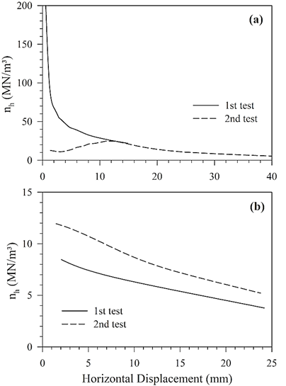
Source: The authors.
Figure 7 Graphs of nh vs. horizontal displacement for (a) natural soil moisture content and (b) flooded conditions.
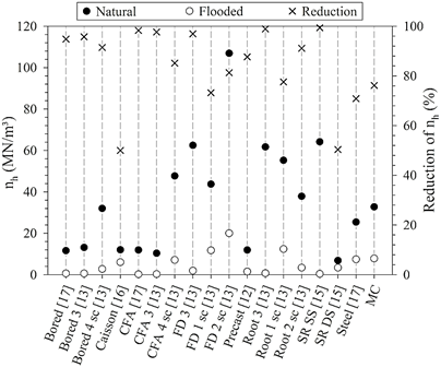
Fig. 8 shows a comparison between the coefficients found for the present micropile and other pile types under the same conditions and the same subsoil profile. In unsaturated conditions, nh for the micropile was higher than most of the piles that did not undergo soil-cement treatment. Under saturated conditions, the new micropile configuration presented even better coefficient than the other pile types, with worse results when compared with the full-displacement and root 1 piles, both with surrounding soil replaced by soil-cement. Regarding coefficient reduction, the proposed micropile showed smaller reduction than most of the cases studied. Lower reductions were observed only for full-displacement pile 1 with soil-cement treatment [13], steel pile [17], caisson [16] and double section steel-rail pile [15]. It is worth noting that these last two cases mentioned presented low nh values even in natural conditions, which explains the low coefficient reduction rate. Overall, the new micropile proved to be a more efficient palliative methodology for the local lateritic soil when compared to the soil-cement treatment.
4. Conclusion
A new post-grouted micropile configuration was presented in this study. The novelty regarding this new procedure lies on the use of a special type of casing tube that acts as drilling equipment, allows global and local injections tube and, after micropile conclusion, acts as structural component. To investigate its laterally top-loaded behavior, a 17 m length and 0.3 m diameter micropile was performed in highly porous lateritic soil and subjected to a total of four lateral load tests, two in natural soil moisture conditions and two in flooded situation. Based on the new post-grouted micropile executive procedure, the results obtained, the analysis performed and the comparisons with previous studies carried out in the same geological and geotechnical contexts, the conclusions are:
The new experimental field presented subsoil profile very similar to the other two tests fields in UNICAMP, composed of highly porous colluvial lateritic soil in the first meters, most solicited range in horizontal loading tests;
In natural conditions, micropile presented one of the lowest loads required to displace the pile head in 6 mm, which was not observed for 12 mm displacements. After full saturation, the micropile showed lower loads for both displacements only when compared with high-rigidity foundation elements, such as full-displacement pile and caisson, and soil-cement treated piles;
For the micropile, the ratios between loads to shift the pile head in 6 and 12 mm under both conditions studied were equivalent only to those piles treated with soil-cement, proving to be a good alternative for the local lateritic soil;
The horizontal reaction coefficient obtained for the micropile with soil at its natural moisture content was 32.7 MN/m³, higher than most cases that were not subjected to soil-cement treatment;
In flooded conditions, the horizontal reaction coefficient encountered was 7.8 MN/m³, with a 76% reduction. These results were better even when compared to the cases that did undergo soil-cement replacement;
The new micropile showed to be more efficient to local lateritic soil treatment when compared to the soil-cement due to its execution process and best results under flooded conditions. It is expected that the micropile performance and design parameters would be even better if post-grouted injections were made in depths closer to the ground surface.

