


 Inglés (pdf)
 Articulo en XML
 Referencias del artículo
 Enviar articulo por email
 Citado por SciELO
  Citado por Google
  Similares en
SciELO
Similares en
SciELO  Similares en Google
 Permalink
1. Introduction
There has been an exponential increase in the use of mobile telephony in recent years, bringing with it large capital investments in the installation of structures to support communications equipment, with optimum characteristics both in terms of design and assembly [1-6]. The typology of these structures includes self-supporting and guyed towers and tubular monopoles [7]. Tubular monopoles require less space and are also versatile in their assembly, characteristics that favor the environment and the economy alike [8]. Tubular monopoles are assembled in sections that are joined using mechanical techniques [9]. The discontinuous nature of the sections and the mechanical contact between them introduce structural uncertainties, rendering them vulnerable to high wind loads [10-12].
The steel construction industry uses bolted assemblies, consisting of mechanical connections, steel plates and high-strength bolts, because of their high-performance and reliable clamping properties [13,14]. The best-known connections for tubular sections are the flange-type and friction-type, the latter being less sensitive to the imperfections that may be found in the plates [15-17]. Calculations and assumptions are required for the analysis of these connections because of the uncertainty associated with environmental factors and the limited availability of models. Taken together, these two factors mean that a true representation of structural responses is not available [18,19]. Ductile failure mode is determined using analytical design methods. However, experimental results suggest that brittle failure is the most common problem [20]. Finite element analysis and destructive testing allow the behavior of bolted flange-type connections to be determined [21,22].
Comparisons between experimental results and those derived from finite element analysis have given satisfactory results in determining the demand for safety and economy in flange-type connections that are subject to pure bending. Studies of flange-type joints under axial load have been useful for studies of bending capacity but are limited in number, confining the availability of general information on the design of good connections [23]. Therefore, research should be conducted using finite element analysis and design methodologies are need to be developed for flange-type connections [24].
One of the methodologies used in the literature is the metamodel (or surrogate) approach, which consists in approximating the response of the finite element analysis using analytical functions that associate input variables with results [25,26]. Optimized methodologies that have been developed for designing steel beam-column, semi-rigid connections and bolt-tightening sequences have performed extremely well in operation [27,28]. An advantage of the metamodel approach is that it reduces the computational cost that complexity represents in the process of design steel structures, which involves a lot of input data. Consequently, metamodeling is important in speeding up both analysis and design [29,30].
This research seeks to develop an optimized methodology for the design of monopole-type telecommunications towers. It uses a parametric metamodel to estimate displacements and stress in monopole sections and flange-type bolted connections. Experimental tests were carried out and simulations in Ansys LS-DYNA Research software employed.
2. Methodology
2.1. Materials
The bending test executed on the prototype structure used ASTM A36 and ASTM A500 steel for the structural sections and ASTM A325 bolts for the connections. The mechanical properties are shown in Table 1.
Table 1 Characteristics of the material models used in Ansys Research.
| Material | Density [kg/m3] | Young's Modulus [MPa] | Poisson's ratio | Yield Limit [MPa] | Maximum Tensile Strength [MPa] | Failure Plastic Deformation |
|---|---|---|---|---|---|---|
| A500 | 7890 | 200000 | 0.3 | 320 | 430 | 0.370 |
| A36 | 7890 | 200000 | 0.3 | 250 | 400 | 0.283 |
| A325 (Bolts) | 7890 | 200000 | 0.3 | 586 | 827 |
Source: the authors
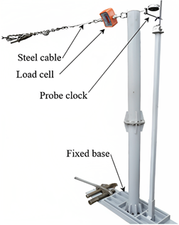
2.2. Equipment
Thickness gauges, a load cell with a capacity of 500 kg, a comparator clock and a torque meter.
2.3. Methods
For the analysis, the functional characteristics of the flange-type bolted connections were investigated and a 3D model made using Ansys SpaceClaim software. The results obtained using the finite element analysis served to parameterize the metamodel. The experimental results of the physical test supported the results of the finite elements analysis of the simulation carried out using using Ansys Research software.
The estimation of loads applied to the structure by finite elements was analyzed according to the ANSI/TIA EIA 222 - G standard, and to data on permanent loads such as the weight of the structure itself and of the accessories and communication equipment. To determine loads produced by the wind, the following data were used: wind speed 90 km/h, topographic category 2, exposure category type B. The load was at different points applied at 6 meter intervals along the 36 meter octagonal section tubular monopole. The structure is described in Table 2. For the joints between sections, a "beam" type element was used, which simulates the presence of the bolts used to join the flanges. The contact between each section’s flanges was "frictionless".
Table 2 Elements included in the 36-meter monopole construction.
| Section | Height [m] | Flanges | # Bolts | Tubular sections | ||
|---|---|---|---|---|---|---|
| Flange thickness [mm] | Diameter [mm] | Face width [mm] | Thickness [mm] | |||
| 1 | 36 | - | - | - | 230 | 6 |
| 30 | 15 | 750 | 16 | |||
| 2 | 15 | 750 | 230 | 8 | ||
| 24 | 20 | 850 | 16 | |||
| 3 | 20 | 850 | 268 | 8 | ||
| 18 | 20 | 950 | 16 | |||
| 4 | 20 | 950 | 306 | 10 | ||
| 12 | 25 | 1050 | 16 | |||
| 5 | 25 | 1050 | 345 | 10 | ||
| 6 | 25 | 1150 | 16 | |||
| 6 | 25 | 1150 | 383 | 12 | ||
| 0 | 38 | 1150 | 24 | |||
Source: the authors
The results obtained for the full-scale structure were used to estimate an equivalent prototype on a reduced scale. This was analyzed using the same software and applying the same conditions as the real structure. It was possible to visualize the deformation trend by measuring deformations at strategic points along the prototype made. To verify the behavior estimated by analysis, a real test was carried out on the prototype. A test bench was assembled, and displacement measurements were made at the top of the prototype, at different levels of force. Fig. 1 shows the results of the prototype test.
With the results of the analysis and the phase test, a simplified model was proposed (focused on areas where there was a change of section, contact between components or border conditions were present). The metamodel had two principal aims: to reproduce displacements caused by the load, which causes horizontal deformation of the structure and structural rotation with respect to its supporting plane. The simplified structure was of the two-dimensional "frame" type, with material properties, section, and length. Strategic points, where contact occurred, there was a change of section or border conditions were present were also specified.
The simplified model is shown by the light blue line in Fig. 2 and the equivalent strut load allowed the visualization of a reduced scheme that facilitated the analysis of the data obtained using finite element analysis. These were obtained for the points where a section change was present that define the behavior of the structure, because of the important deformations that occur, in particular in the flanged connections.
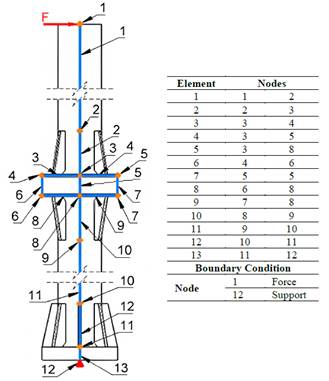
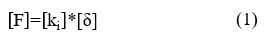
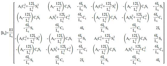
The prototype was assembled using tubular sections of 101 mm (4 in.) diameter with 4 mm (3/16 in.) thickness; the flanges were 175 mm (6 7/8 in.) in diameter and 10 mm (3/8 in.) thick; the gussets were triangular, with a 35 mm (1 3/8 in.) base, 101 mm (4 in.) height and 6 mm (1/4 in.) thickness in the upper section and 8 mm (5/16 in.) in the lower section. The prototype was 2 meters tall. Fig. 2 shows the elements and nodes used. Each node had 3 degrees of freedom: displacement in the X axis (δXi), displacement in the Y axis (δYi) and rotation in the Z axis (θi), with force applied at node 12 (F=2533.4 N). Each element had its equivalent stiffness (ki), with the result that the equilibrium could be described using eq. (1):
Where:
Ai = Equivalent area of the element.
Ii = Inertia of the element
Li = Length of the element
Ei = Modulus of elasticity of the element
Si = Sine of the angle of element orientation
Ci = Cosine of the angle of element orientation
Elements 2, 10 and 12 are the joints between sections. These displayed a non-linear behavior. For this reason, the metamodel was required to considers this reinforced section, calculating an equivalent length that represented the physical properties of the reinforced section, using eq. (2):
Where:
Lequ = Equivalent length
Ib = Inertia of the reinforced assembly: flanges, bolts, gussets.
3. Results
According to the finite element analysis the displacement of the 36000 mm structure was about 400 mm, resulting in a rotation angle of 1/90. The angle of rotation was equal at all heights, allowing an equivalent deformation for the prototype to be calculated:
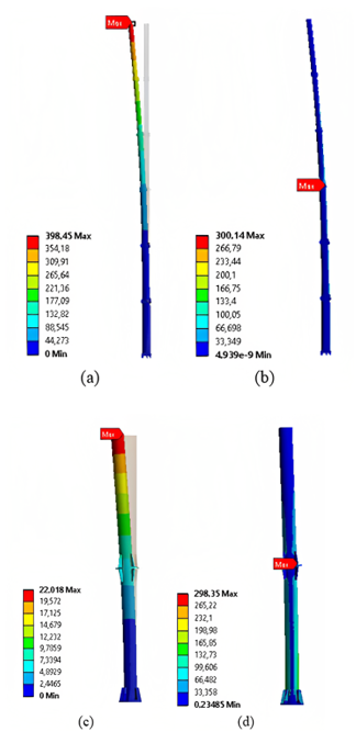
In addition to the figures for displacement, a stress of 300 MPa was obtained, located in section 3 at a height of 18 meters. Data for the prototype was obtained using the description provided in Fig. 2. Fig. 3 shows the stress and displacement results both for the 36-meter structures and the prototype.
Source: the authors
Figure 3 Finite element analysis results. (a) Displacement of the 36-meter monopole, (b) Maximum stress of the 36-meter monopole located at 50% height, (c) Displacement of the monopole prototype, (d) Maximum stress of the monopole prototype located at 50% height.
Table 3 shows the results obtained by physical testing, finite element analysis and the data estimated using the metamodel. Note that the data for the three types of analysis are very approximate.
Table 3 Results of physical testing, finite element analysis and metamodel.
| Force [N] | Z-axis displacement [mm] | ||
|---|---|---|---|
| Physical Test | FEM Solid | Metamodel | |
| 196.2 | 1.6520 | 1.7053 | 1.7422 |
| 392.4 | 3.2300 | 3.4105 | 3.4844 |
| 588.6 | 4.9533 | 5.1158 | 5.2266 |
| 784.8 | 6.5500 | 6.8210 | 6.9688 |
| 981.0 | 8.3067 | 8.5263 | 8.7110 |
| 1177.2 | 10.0733 | 10.2320 | 10.4532 |
| 1373.4 | 12.1800 | 11.9370 | 12.1954 |
| 1569.6 | 13.6500 | 13.6420 | 13.9376 |
| 1765.8 | 15.5667 | 15.3470 | 15.6798 |
| 1962.0 | 17.1217 | 17.0530 | 17.4220 |
| 2158.2 | 19.1233 | 18.7580 | 19.1643 |
| 2354.4 | 20.9300 | 20.0190 | 20.9075 |
| 2533.4 | 22.5900 | 22.0190 | 22.4959 |
| 2550.6 | 22.7467 | 22.1630 | 22.6487 |
Source: the authors
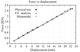
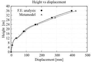
Fig. 4 shows the comparative graph of the data presented in Table 2, showing that the three types of analysis follow the same trend.
Source: the authors
Figure 4 Comparison of results for the prototype, obtained by the physical test, finite element analysis and metamodel.
Table 4 shows the results of displacements of the 36-meter monopole at different heights and their respective metamodel. The maximum variation between results were 8.44%.
Table 4 Results of the displacements of the 36-meter monopole and its respective metamodel.
| Height [m] | Z-axis displacement [mm] | ||
|---|---|---|---|
| FEM Solid | Metamodel | Variation [%] | |
| 36 | 398.45 | 425.60 | 6.38 |
| 30 | 268.63 | 290.32 | 7.47 |
| 24 | 159.96 | 173.43 | 7.77 |
| 18 | 82.65 | 90.27 | 8.44 |
| 12 | 34.28 | 37.42 | 8.39 |
| 6 | 7.89 | 8.58 | 8.04 |
| 0 | 0.02 | 0 | 0.00 |
Source: the authors
Fig. 5 shows the comparative graph of the results presented in Table 3. The results obtained in the prototype test validate the three-dimensional model of the analysis of the 36-meter structure. That is, the results of the analysis are reliable and may be used to compare the data calculated using the metamodel.
Source: the authors
Figure 5 Comparison of results obtained in the finite element and the metamodel analysis of the 36-meter monopole.
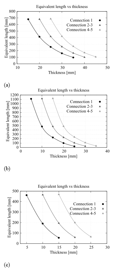
The metamodel considered the stiffness effects caused by bolted joints, for which an equivalent length with its respective stiffness was established. The results are shown in Table 5.
Table 5 Equivalent lengths for different combinations of flange thickness and numbers of bolts.
| Joint | 6 m (Connection 1) | 12 m -18 m (Connection 2-3) | 24 m - 30 m (Connection 3-4) | |||
|---|---|---|---|---|---|---|
| Number of Bolts | Thickness | Equ. length [mm] | Thickness | Equ. length [mm] | Thickness | Equ. length [mm] |
| 8 | 35 | 98 | 40 | 103 | 45 | 108 |
| 30 | 161 | 35 | 166 | 40 | 171 | |
| 25 | 258 | 30 | 263 | 35 | 268 | |
| 20 | 413 | 25 | 418 | 30 | 423 | |
| 15 | 679 | 20 | 684 | 25 | 689 | |
| 16 | 25 | 26 | 30 | 31 | 35 | 36 |
| 20 | 101 | 25 | 106 | 30 | 111 | |
| 15 | 229 | 20 | 234 | 25 | 239 | |
| 10 | 477 | 15 | 482 | 20 | 487 | |
| 5 | 1114 | 10 | 1119 | 15 | 1124 | |
| 24 | 15 | 55 | 20 | 60 | 25 | 65 |
| 10 | 191 | 15 | 196 | 10 | 201 | |
| 5 | 461 | 10 | 466 | 15 | 471 | |
Source: the authors
Fig. 6 shows the comparative plots of data from Table 4, showing the dependence of thickness on effective length.
4. Conclusions
The physical test permitted the accurate determination of the contacts between "frictionless" flanges, and the representation of the bolts with "beam" type element, which were applied using the Ansys Research software and reproduced results in accordance with reality.
When compared with the results of the physical test, the results for displacement and maximum stresses obtained using the finite element analysis validated the methodology used in the metamodel approach.
The number of bolts had a direct influence on the thickness of the flanges; it is also evident that the structure’s joint compartments followed a decreasing exponential trend.

