


 Inglés (pdf)
 Articulo en XML
 Referencias del artículo
 Enviar articulo por email
 Citado por SciELO
  Citado por Google
  Similares en
SciELO
Similares en
SciELO  Similares en Google
 Permalink
1. Introduction
The organizations are currently facing a very complex and competitive environment. Today, technology is a key factor for productivity, innovation and competitiveness. Technology can constitute a basic element of differentiation of the company, so its management derives its ability to improve its processes, to create new products and/or services, to enter new markets. Technological innovation is a core component because it creates new value by enabling people and businesses to use existing resources more efficiently.
With technology management, companies seek to maximize their competitive advantages, based on their capacity for development and technological innovation in obtaining and systematically using their technological and organizational means, adding value to new, different and possibly better products, or at least, meeting the needs and requirements of the client.
2. Literature review and problem statement
The development of new technologies in power electronics has produced increasingly efficient systems in terms of electrical energy management, however, a disadvantage of these systems has been the increase in heat generation due to the use of power transistors, IGBT (insulated gate bipolar transistor) or MOSFET (metal oxide semiconductor field effect transistor) [1].
The heat generated in a power electronic system is mainly due to its high frequency and existing density of transistors used (IGBT or MOSFET). This heating has a direct effect on component failure. This is due to the component materials since in operation they reach high temperatures (over 100 ° C). Other undesirable effects are internal forces generated by thermal expansion and contraction. Both factors, the increase in temperature and internal stress, limit the useful life of electronic systems to a certain amount of heating and cooling cycles [1].
The technological advance in research of power transistors (IGBTs) has developed IGBTs modules, which are used to develop power converters. To satisfy this need also involves greater heat generation, which leads to a growing need for new ideas and technologies for heat dissipation in the implementation of new modules [2].
For this reason, the design of heat sinks emerges with the tendency to evolve through the study of heat transfer. Applying materials and technologies that dissipate heat more efficiently and guarantee the operation of the IGBT modules within the design temperatures during their useful life. Results of other investigations indicate that the factors to improve the performance of a heatsink are the increase in the length, width, height, thickness, and number of fins for a compact rectangular heatsink, with straight rectangular fins of uniform section [1,3-7].
Some of the key characteristics of a heatsink must be black finished, to improve thermal radiation [3]; that is modular [4]; and even that the design is of micro-channels in the pressure drop [5,6]. The effect of thickness is important, in addition to the influence of the type of material used [7]; finally, to consider a coolant [4]. The design demands on a heatsink due to space, weight and material limitations make a computer design necessary before any prototype.
A simulation computer package such as SolidWorks® or another [8,9] can then be used to reproduce the operation of a heatsink in its traditional way also serve to propose new configurations. A new configuration may consider more fins and different geometric shapes. These configurations can be preliminarily evaluated to choose the most promising one, with which you can proceed to the prototype construction stage.
This work philosophy allows significant savings, not only in time, but also in resources, by testing the configurations in a virtual environment and not having to build each case in a workshop and then test it. The efficient function of a heat sink depends on a rapid transfer of thermal energy from an object to the heat sink [10]. This can be achieved through an application of forced convection [4,9,11-14] or natural convection [8,15-17].
Exist the need to design and manufacture a heatsink that meets the heat dissipation requirements of IGBT power transistors. Consider the possible combination of two of the most used materials such as aluminium [8,17,18] and copper [8,17]. In addition, it is contemplated to use refrigerant liquid through the microchannels for cooling of said components.
Alternatively, the 30 kW DC/DC converter to be developed has the function of controlling energy transfer from a voltage level of 750 V to another level of 187.5 V., as well as high frequencies (30 kHz to 70 kHz). For this device to perform its function in optimal conditions, it is necessary to regulate its temperature in an interval of 25 - 50 ° C, which is necessary to use a heatsink that will release the thermal energy of the IGBT, avoiding damage to the system due to overheating.
The heatsink currently being used in power converter testing is one that was not expressly designed for this function and is therefore heavy and oversized.
Faced with this situation, a heatsink is developed that responds to the needs of the IGBT transistor modules that are currently used, with the appropriate material, performing tests and using a refrigerant that will circulate through micro-channels, to cool the materials, that is in order to make a lightweight and functional system.
3. Objectives of the study and general specifications
The objective of this project is to use the “Total Design” methodology [21], although in this case, neither the first nor the last stage was included, because, due to project limitations, it consisted only of designing, modelling and manufacturing the prototype (heat sink), without the need to have a market niche or consider the demand for it.
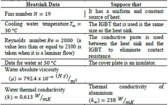
For the design of the heatsink of the 30-kW converter of the project “Energy saving systems for the trains of Mexico City metro” [22], the extreme operating conditions of the IGBT module were considered. It is shown in Table 1.
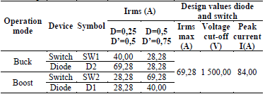
It is considered that the converter will be able to operate under the load conditions for an indefinite time, which in practise can only happen during the tests performed. The application requirements consider the operation of the converter at constant power. Used for loading and unloading a supercapacitor module, so the maximum load condition occurs during short periods of time.
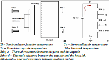
The IGBT model used is a CM600DU-24NFH, which is a half-bridge module. The component-heatsink assembly diagram is shown in Fig. 1, which is associated with the thermal or heat flow circuit [23].
Source: Own elaboration
Figure 1 a) Heatsink component assembly, b) Thermal model used to calculate the heatsink.
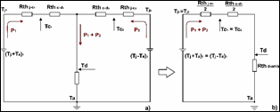
The thermal circuit is the one you see in Fig. 2 a). The situation (both electrical and the relationship between the heatsink assemblies) will be assumed to be symmetrical. Since one of the components was a receiver of heat from the other, with this limitation imposed, the thermal circuit can be simplified as shown in Fig. 2 b).
Source: Own elaboration.
Figure 2 a) Thermal model for two components, b) Simplified thermal model for two components.
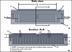
Channel heat sinks can be used to cool electronic devices with higher thermal flux [Dang et al., 2010]. In Fig. 3 the parameters of: W c = 0.003302 mWc = 0.003302m W w = 0.00635m b = 0.0254m L = 0.1016 m t = 0.0127 m to start generating the calculations of the designed heatsink are specified.
a) Heatsink Parameter Calculation
Source: Own elaboration.
Figure 3 Heatsink views: a) Side view and, b) Heat sink section for two IGBT modules.
From the above, what is specified in Table II is considered. The mass water flow through all channels can be calculated. On the other hand, the Nusselt number is used to calculate the heat transfer coefficient.
Likewise, the effective resistance (Reff) between the elements of the IGBT that forms the heat source and the cooling water, and finally, neglecting the edge effects, the allowable heat dissipation rate (Qdisipador) will be calculated using the condition that the temperature difference between the fountain and water do not exceed 20 ° C.
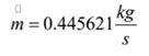
b) Calculation of the total mass flow rate m :
This speed can be calculated from the definition of the Reynolds number:
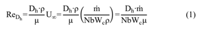
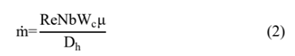
Solving for m de (1) we have:
but first, it must be found
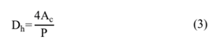
Then substituting in equation (3), we have:
Now substitute into equation (2), to find m :
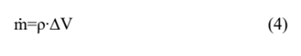
The total mass flow rate is used to determine the capacity of the water pump that was used for the system, using the following formula:
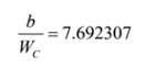
The canal cavity ratio is:
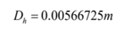
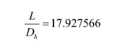
The relationship between the cavity length and the hydraulic diameter is:
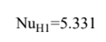
With these relationships, the flow in the channels is fully developed and the Nusselt number is calculated according to [Bergman et al., 2011], then we have:
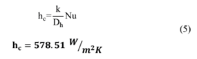
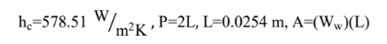
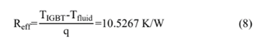
c) Calculation of the heat transfer coefficient by h c
With the formula:
d) Calculation of fin efficiency n f
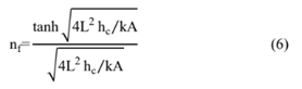
The data we have about this fin, in particular, are:
First, the common factor is calculated with the following formula:
Substituting this value in equation (6), we have:

Therefore, the assumption that the flow channel is isothermal is correct.
e) Calculation of the effective thermal resistance R eff:
This value determines the capacity of the material to oppose heat flow.
f) Calculation of heatsink heat transfer
Source: Own elaboration.
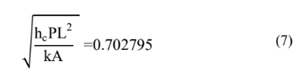
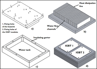
Figure 4 a) Top view of the heatsink, b) Heatsink fins, c) Heatsink water tank, d) Heatsink assembly.
It is known that the temperature difference between the heat source and the water should not exceed between the two, so the conversion is made to Kelvin and it is necessary, then the heat transfer for half a channel is:
Therefore, for the entire heatsink under, the assumption that the heat source is uniform and constant we have:

This data represents the amount of heat that the heatsink must physically release when the system is operating.
Once the design of the heatsink has been mathematically verified, we move on to 3D CAD modeling, using the SolidWorks® tool for this.
In Fig. 4, the parts of the heatsink are observed.
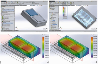
For the simulation and modeling of the prototype, the module “SolidWorks Simulation” is used. In Fig. 5 it is possible to observe the analysis performed, and the thermal
Source: Own elaboration.
Figure 5 a) Configuration and selection of the analysis type, b) Heatsink simulation with coolant, c) Thermal simulation with Al material, d) Thermal simulation with Cu material.

Source: Own elaboration.
Figure 7 Simulation and calibration, coordinate system adjustment, planned, grinding, fin machining, machined and assembly.
simulation with the two selected materials and to determine which material dissipates more heat. Fig. 5 b) shows the maximum temperature already reached with circulating coolant, which is 31.17 ° C, that is, well below the required 50 ° C.
4. Materials and methods
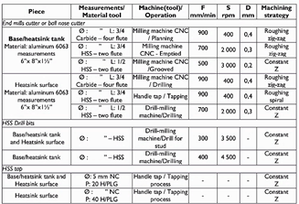
Once the modeling and the simulation of the behavior of the developed system were concluded, the manufacturing of the parts continued [24,25]. In Fig. 6 the necessary and summarized data of the parameters and correct and previous conditions used to the machine, the components are specified.
Fig. 7 shows some of the processes that were carried out, using a numerical control milling machine, which allowed giving close and adequate tolerances for the final assembly of the product.
5. Results
The analysis of the results starts after carrying out the functionality tests and efficiency of the developed heatsink. The temperature monitoring was carried out utilizing sensors, an interface with the computer was generated through a USB port, connected with an Arduino card shown in Fig. 8.

The samples were recorded every 2.33 seconds, being an average of 722 samples in 30 minutes.
The tests were carried out using two types of coolant, one test used water, and the other used antifreeze fluid, which is normally used for cooling automobile engines.
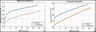
Fig. 9 a), shows a graph of the temperature monitored on the contact face of the IGBTs (in this case a resistance of 1000 watts), as can be seen, when water was used as a cooling liquid the temperature reached was higher than when car antifreeze was used.
Source: Own elaboration.
Figure 9 a) Upper face temperature counted on the heat sink, b) Underside temperature of the heatsink.
The graph presented in Fig. 9 b), shows the monitored temperature on the opposite face of the heat sink, that is, the bottom of the device. In this case, it can also be observed that as in the previous graph, when water was used as coolant the temperature was higher than when automobile antifreeze was used.
The cooling liquid, staying in direct contact with the cooling fins, also increases its temperature as the heat sink's operating time elapses.
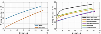
In the graph of Fig. 10 a), the temperature variation is observed when water or automobile antifreeze was used as a coolant. Alternately, all the temperatures monitored in both tests are plotted, as can be seen in Fig. 10 b). The highest temperatures were recorded with the use of water, in this way it can be concluded that the use of antifreeze presents a better heat transfer since it maintains a lower temperature in the heat dissipation system.
Source: Own elaboration.
Figure 10 a) Coolant temperature comparison, b) Temperature comparison chart using water and antifreeze.

In Fig. 11 another test was carried out, using a square grill of 1000 watts of constant temperature, in order to have a greater contact surface on the heatsink. In this case, the source was placed at a temperature of 244 °C on the contact surface of the heatsink.
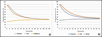
The temperature measurements were made in three areas: inlet and outlet of the coolant, also in the tank, as in the previous tests, water and antifreeze were used. It can be seen in Fig. 12 a) and b) respectively. In these graphs, the heatsink temperature drops uniformly from 90 °C to 40 °C approximately in a time of 40 seconds at the inlet and in an approximate time of 60 seconds at the outlet, likewise, the water temperature rises from 27 °C to 32 °C in 40 seconds.
Source: Own elaboration
Figure 12 a) Tests carried out with water as a refrigerant, b) Tests carried out with antifreeze as a refrigerant.
From this point on, the variation in temperatures is minimal over a longer period, until reaching stability of 33 °C. Fig. 12 b) shows that the heat sink temperature drops uniformly from 85 °C to 36 °C approximately in a time of 64 seconds at the inlet and outlet, likewise, the water temperature rises from 22.5 °C to 29 °C in 64 seconds. From this point on, the variation in temperatures is minimal in a longer period, until reaching stability at 29.8 °C.

It is worth mentioning that, in all cases, the coolant was used at room temperature, therefore, after having carried out the studies, it is confirmed based on the results that the best option to use is automotive antifreeze.
Fig. 13 shows the temperature drop from 240 °C to 44.6 °C when placing the square grill in contact with the heatsink using a coolant. To verify and determine the temperature a thermal imager (FLIR brand, model E6) was used on the surfaces of the heatsink.
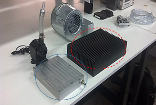
It should be noted that the size of the designed heat sink is 25% less than the heat sink that was initially used in the project, meeting the project objectives and therefore the research work in a timely manner. The dimensions of this prototype are length 21 cm, width 15.5 cm, and height of 4.5 cm, and the one that was initially had was length 32 cm, width 21.7 cm, and height of 9 cm.
In Fig. 14, you can see the difference in sizes between both heatsinks (the one proposed by this analysis and the one that ordinarily operates). From the tests carried out, it can be concluded that by using automotive antifreeze, better results are obtained, as could be seen in the various images displayed. There is a significant variation of 7 °C concerning the use of water. These tests were carried out in 30 minutes, during which time the temperature stabilized. On the other hand, the thermal resistance was working at a constant temperature of 196 °C and the contact surface was kept below 50 °C, which is what was expected based on the mathematical analysis developed.
Likewise, comparing the graphs of Fig. 12 it can be seen that the antifreeze remains below the water temperature in the same period of working time.
6. Conclusions
Using Pugh's methodology, a smaller size heat sink was obtained, with thicker fins, and with better work efficiency, applying forced convection with cooling liquid, generating a considerable improvement in the cooling of the power modules. IGBT, thus complying with the characteristics of innovation, generating an appreciable added value by the user. Once the prototype was designed and evaluated, the parts were machined using numerical control machines, generating a precise assembly, with the expected quality, allowing to obtain a prototype without leaks with correct operation. Since the objective of lowering the temperature and maintaining it constantly in relation to what was requested by the client was met, not exceeding 50 °C. Corroborating this in advance in a simulated way with software and then physically with the help of sophisticated equipment such as the thermal graphic camera.

