


 Inglês (pdf)
 Artigo em XML
 Referências do artigo
 Enviar este artigo por email
 Citado por SciELO
  Citado por Google
  Similares em
SciELO
Similares em
SciELO  Similares em Google
 Permalink
1. Introduction
According to [1] Induction motors are widely used in industrial processes to supply mechanical power and thus perform tasks that require great effort. In these machines there is difficulty in the implementation of linear control techniques, since the speed at which they rotate and the power they deliver depend on the frequency of the input signal and the supply voltage.
According to [2] Studies show that electric motors by using 60% of industrial electricity are greatest consumer in industrial equipments and have considerable potential for energy efficiency.
According [3] Industry consumes about 40% of the electricity, of which two thirds are used by electric motors. Variable Speed Drives (VSDs), which regulate the speed of motors, can reduce their energy consumption by 50% in many applications, but less than 10% of motors are equipped with such a device.
According [4] The 24-sector SVPWM techniques overcome the drawbacks of PWM and offer great advantages from the point of view of harmonic performances and the easiness in digital implementation. However, the algorithm and digital implementation process are still rather complex.
Therefore, it is proposed to analyze if the SVPWM control technique is more efficient than the conventional PWM control technique with lucas nulle laboratory equipment under load operating conditions.
The analysis is based on the mathematical modeling of the space vector pulse width modulation control using the Simulink electrical library and subsequently implementing the system with Lucas nulle laboratory equipment using a 0.37 and 1 kW triphasic induction motor with a 1.5 N*m load at 200 rpm, 1300 rpm, 3600 rpm operating speeds.
Finally, it is considered that the analysis of the efficiency in the control stage will allow to apply these techniques at an industrial level with knowledge under load operation and will serve as a tool for the industrial community related to the operation of three-phase induction electric motors.
2. Literature review
2.1. Induction motor
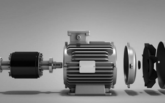
Fig. 1 shows an induction motor with a squirrel cage rotor. A three-phase set of voltages has been applied to the stator and a three-phase set of currents flows from it. These currents produce a counterclockwise rotating BS magnetic field. [5]
2.2. Frequency inverter
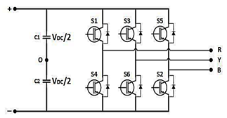
The variable frequency drive as seen in Fig. 2 is the effective solution to improve energy efficiency, reduce energy consumption and carbon dioxide emissions. On this page we will talk about the characteristics, advantages and operation of variable frequency drives.
2.3. Space Vector Pulse Width Modulation (SVPWM)
One of the main characteristics is that the entire triphasic system is represented by a single vector. The SVPWM technique refers to the selection of the switching states of the inverter switches in each existing period by means of times and a determined order. [6]
According [6] there are several applications in which SVPWM modulation presents advantages, for example, in control of three-phase motors, the motor variables can be broken down to have independent control of speed and torque. Also for electric power generation through devices that deliver DC direct voltage, or any application in digital controllers because its implementation becomes simpler than any other PWM modulation.
2.3.1 Switching states in inverters with SVPWM modulation
One In Fig. 2, it is observed that the three-phase inverter has 6 switching devices that will be called switches, the power supply is direct current, the assigned switches S1, S2, S3, S4, S5, S6 of the three-phase inverter they can never be both from the same branch closed. [7]
In state ON or logic 1 because a short circuit occurs in the inverter; that is, while S1 = 1 compulsorily S4 = 0, and so on with the two remaining pairs being their inverse complement. [7]
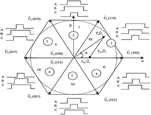
The switching states are determined only with the upper switches, in this case they are S1, S3 and S5, there are 8 different states with a switching logic that generate sinusoidal triphasic signals, the states are presented in Fig. 5. [7]
The vectors 𝑉0 and 𝑉7 are called null vectors or zero vectors. This occurs when the 3 upper switches are closed or open and there is no voltage, on the contrary, the other vectors are called active vectors and with the Clarke transform, Fig. 3 is presented, which corresponds to the voltage values in each state. [7]
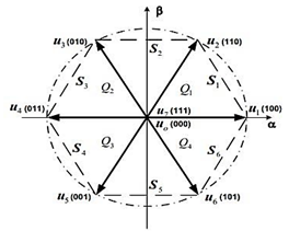
In Fig. 4, the sectors are represented as S1, S2, S3, S4, S5, S6, the quadrants as Q1, Q2, Q3, Q4, the active vectors represent each edge and the 2 null vectors are in the center of the flat since they do not have a modulus value. These vectors are also called director vectors, they are the only ones that the 6-switch three-phase inverter can generate, therefore they are fixed in the complex plane, the more vectors there are in the plane, the more sinusoidal the output signal is and it directly produces fewer harmonics. [7]
The reference vector is the one that rotates throughout the plane presented above, it switches between the two director vectors depending on the sector in which it is located. [7]
2.3.2 Switching times
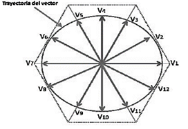
A The reference vector 𝑉𝑟𝑒𝑓 can be represented in the complex plane, but only with its closest direction vectors. According to this representation, the equations to determine the activation times of each vector are eq(1) eq(2) eq(3) eq(4):
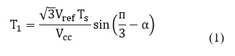
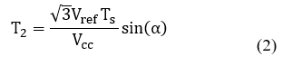
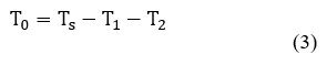
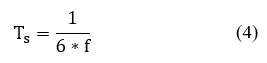
Where:
𝑇𝑠: Period in each sector
𝑓: Frequency of the sinusoidal signal of the system, divide by 6 because there are 6 sectors
V (ref): Module of the reference vector
∝: Angle between the reference vector and the direction vector
𝑉⃗ 1 its values are between 0° and 60°
𝜋/ 3: Angle between the two direction vectors, is equal to 60°
𝑇1: Application time of the direction vector 𝑉⃗ 1
𝑇2: Application time of the direction vector 𝑉⃗ 2
𝑇0: Time of application of the null vector 𝑉⃗ 0 𝑜 𝑉⃗ 7
2.3.2 Switching sequence
The activation time of the null vectors depends a lot on the distribution of the duty cycles, the use of two null vectors minimizes the content of harmonics in the signal but the switching losses increases, while with a single vector switching losses are minimized but harmonics increase, the switching sequences can be seen in table 1. [7]
With this, the shapes of the output signals in each sector would be those shown in Fig. 5:
Table 1 Vector sequence using 2 null vectors.
| Zone | Sequence |
|---|---|
| 1 | V0-V1-V2-V7-V2-V1-V0 |
| 2 | V0-V3-V2-V7-V2-V3-V0 |
| 3 | V0-V3-V4-V7-V4-V3-V0 |
| 4 | V0-V5-V4-V7-V4-V5-V0 |
| 5 | V0-V5-V6-V7-V6-V5-V0 |
| 6 | V0-V1-V6-V7-V6-V1-V0 |
| 7 | V0-V1-V2-V7-V2-V1-V0 |
| 8 | V0-V3-V2-V7-V2-V3-V0 |
Source: The author
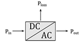
2.4 Inverter efficiency measures
The efficiency of the inverter is a value that indicates how much continuous energy (input power) is converted into alternating energy (output power). In general, two types of electrical losses are considered in this equipment: a) those dependent on the input power, caused by the switching of the power switches and the losses in the connectors on the DC side, and; b) those of an independent type, produced in the inverter itself, inherent to the operation of its circuits. Both types of losses make up the characteristic curve of the efficiency of an inverter as seen in Fig. 6.[7]
3. Equipment and system implementation
The equipment, procedures and conditions to evaluate the operation of the system are described below.
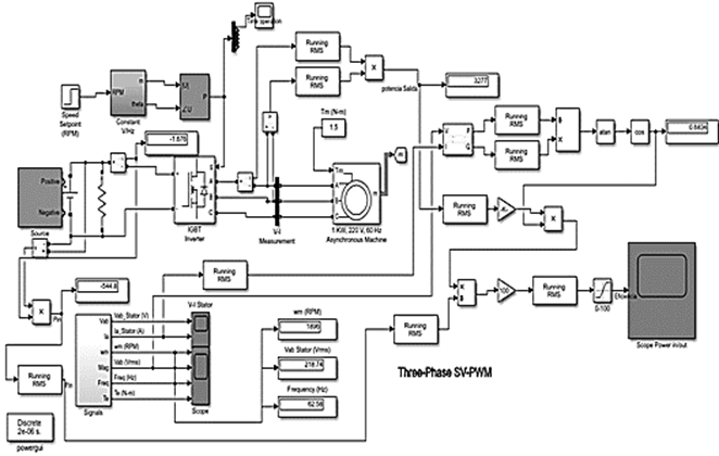
The investigation is carried out using the simulink electrical library of the SVPWM control of an induction motor where the commutation times are calculated to generate the space vector and the experimental method to determine the efficiency of the system.
In addition, the technical characteristics of each of the elements of the module "Training systems for electric machines, drivers and power electronics" used in the physical implementation of the system to evaluate the behavior are detailed.
The general diagram found in Fig. 7 shows the overall system of the controller, the motor and the measuring instruments, the blocks obtained by the Clark transformation of Park and the times of the space vector.
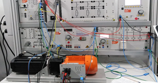
Fig. 8 shows the elements that were used to validate the mathematical model of this project was carried out through the module "Training systems for electric machines, drivers and power electronics" this didactic module has all the necessary elements to validate the operation of the physical system, these elements are described below.
Fig. 9 shows the mains voltage supply for alternating and three-phase current. The power supply of the network has been adapted by the company Lucas Nulle especially for use with electrical machines, the characteristics are detailed below.

Source: The author.
Figure 9 Source of Training systems for electric machines, drivers and power electronics
Outputs: o Three-phase current: L1, L2, L3, N through 4mm safety sockets
Protection devices: o Motor protection circuit breaker, adjustable from 6.3A to 16A o Low voltage circuit breaker o Safety disconnect.
Mains connection: 3 x 230/400V, 50/60Hz via CEE connector with 1.8m cable.
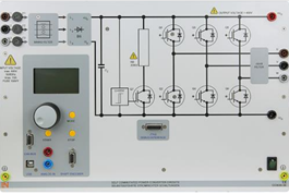
Fig. 10 shows the forced commutation static converters teaching system, which allows the assembly and analysis of power electronics circuits with IGBTs. In addition to power semiconductors, the system has activation and measurement devices for all variables. important.
Source: The author.
Figure 10 Forced Commutation Static Converters of Training systems for electric machines, drivers and power electronics.
Control unit with 6-pulse IGBT inverter
Activation and measurement unit controlled by means of digital signal processing
Integrated measurement of 3 currents and 6 voltages
Electronic control and disconnection due to overvoltage and overload
Integrated control function for mounting controlled drives
Interface for integration to the Matlab unit
Selectable PWM frequencies
USB port
Input for incremental sensor
Analog input
Integrated brake chopper
Connection voltage: 3 x 47 V at 220 V, 60 Hz
Maximum output power: 1 kVA.
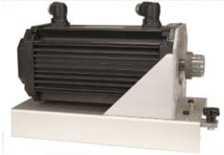
Fig. 11 shows the servomotor test bench is a complete system for the analysis of electrical machines and drives. It consists of a digital control unit, a brake and the ActiveServo software. The system combines the latest technology with easy handling.
The brake forms a self-cooling, asynchronous servo brake unit with resolver. The connection of the motor cable and the sensor is made by means of a plug-in connector proof against polarity reversal. The machine has thermal control and forms, with the control unit, a drift-free drive and brake system that does not need calibration.
Source: The author.
Figure 11 Dynamic servo machine test system of Training systems for electric machines, drivers and power electronics
Maximum turning speed: 4000 rpm
Maximum torque: 10 Nm
Temperature monitoring: by means of a continuous sensor (KTY)
Resolution of the resolver: 65536 pulses / revolution
Dimensions: 275 x 210 x 210 mm (B x H x D).
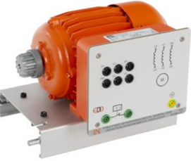
Fig. 12 shows the image of the first machine used in the project, it has the following characteristics.
Rated voltage: 400/230 V, 60 Hz
Rated current: 0.95 A / 1.65 A
Rated speed of rotation: 3600 rpm
Rated power: 0.37 kW
Cos phi: 0.76
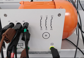
Fig. 13 shows the image of the second machine used in the project, it has the following characteristics.
Rated voltage: 400/230 V, 60 Hz
Rated current: 3.8 A / 2.2 A
Rated speed of rotation: 3600 rpm
Rated power: 1 kW
Cos phi: 0.83.
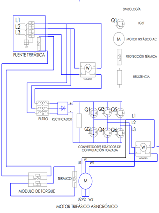
Fig. 14 shows the diagram connection of the system.
Source: The author.
Figure 12 Three phase induction machine of Training systems for electric machines, drivers and power electronics.
Source: The author.
Figure 13 Three phase induction machine of Training systems for electric machines, drivers and power electronics.
4. Methodology
To analyze the efficiency of the controller using the space vector pulse width modulation technique, the simulink library for control of a three-phase induction motor using SVPWM is used.
Subsequently, the parameterization of the electrical data of the equipment that is physically available in this case of the equipment of the "Training systems for electric machines, drivers and power electronics" created by the Lucas Nulle brand is carried out.
Next, three operating scenarios are considered at 200rpm at 1300rpm at 3600rpm, these three speeds operated with a load of 1.5 Nm, then power meters are implemented at the input and output of the controller dividing the output power for the power of input to obtain a value that is multiplied by 100%, additional semiconductor switching times are displayed.
Next, the physical system is implemented with the equipment of the "Training systems for electric machines, drivers and power electronics" according to the diagram in Fig. 16 where a wattmeter is connected to the input and output of the forced commutation static converter, then The torque module is configured to apply the load of 1.5Nm to monitor the system at speeds of 200rpm, 1300rpm and 3600rpm, a stabilization time of 1s is considered to take the values, avoiding starting values.
5. Results and analysis
An analysis of the SVPWM system is carried out to know the behavior and limits of operation, it is evaluated taking into account three speeds 200 rpm 1300rpm and 3600rpm maintaining a constant torque of 1.5N*m in each case of speed parameter the efficiency of the controller is evaluated.
5.1. Case A 200rpm simulink.
Fig. 15 shows the input parameters to evaluate case A. The trigger signals for the semiconductor bridge in semiconductor Q1 changes state in the order of 248.641 ms, this signal can be seen in Figs. 16 and 17.
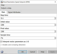
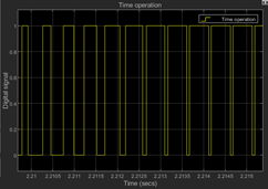
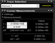
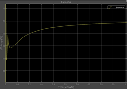
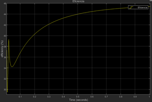
Fig. 18 shows the behavior of the efficiency of the DC to AC voltage conversion stage. At the beginning of the curve, an unstable section is presented, this is due to the stabilization time of the system start-up, later it reaches an efficiency of 69%.
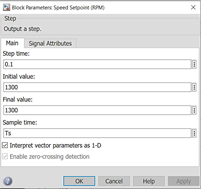
5.2. Case B 1300rpm simulink.
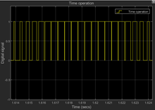
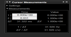
Fig. 19 shows the input parameters to evaluate case B. The trigger signals for the semiconductor bridge in semiconductor Q1 changes state in the order of 31.322 ms, this signal can be seen in Figs. 20 and 21.
Fig. 22 shows the behavior of the efficiency of the DC to AC voltage conversion stage. At the beginning of the curve, an unstable section is presented, this is due to the stabilization time of the system start-up, later it reaches an efficiency of 49%.
5.3 Case C 3600rpm simulink.
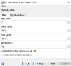
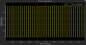
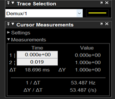
Fig. 23 shows the input parameters to evaluate case C. The trigger signals for the semiconductor bridge in semiconductor Q1 changes state in the order of 16,696 ms, this signal can be seen in Figs. 24 and 25.
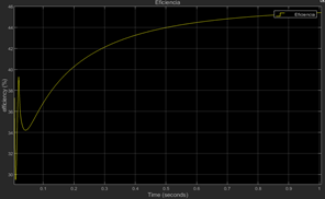
Fig. 26 shows the behavior of the efficiency of the DC to AC voltage conversion stage at the beginning of the curve, an unstable section is presented, this is due to the stabilization time of the system start-up, later it reaches an efficiency of 45.4%.
5.4 Case A 200rpm in the training systems for electric machines, drivers and power electronics
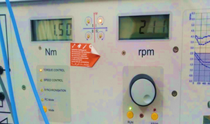
In Fig. 27, in the first case, the torque input data is set at 1.5N*m and the speed at 200rpm.
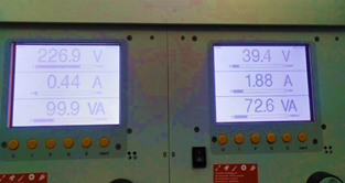
With the data set in the first case, the results presented in Fig. 28 are obtained, a power of 72.6 VA at the output and a power of 99.9 VA at the input, generating an efficiency of 72.67%.
5.5. Case B 1300rpm in the Training systems for electric machines, drivers and power electronics
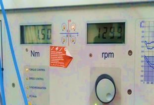
In Fig. 29, in the second case, the torque input data is set at 1.5N*m and the speed at 1300rpm.
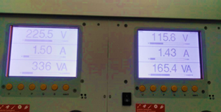
With the data set, the results presented in Fig. 30 are obtained with a power of 165.4 VA at the output and a power of 336 VA at the input, generating an efficiency of 49.22%.
5.6. Case C 3600rpm in the Training systems for electric machines, drivers and power electronics
In Fig. 31, in the second case, the torque input data is set at 1.5N*m and the speed at 3600rpm.
With the data set in the second case, the results presented in Fig. 32 are obtained, a power of 214.4 VA at the output and a power of 453 VA at the input, generating an efficiency of 47.32%.
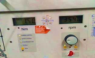
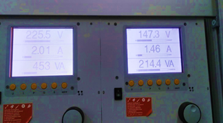
Table 2 Summary of cases physical system and mathematical model.
| Cases | Speed (rpm) | Lucas Nulle Module (%) | Simulink mathematical model efficiency (%) | Error (%) |
|---|---|---|---|---|
| TO B. C. | 200 1300 3600 | 72.67 49.22 47.32 | 69 49 45.4 | 5 0.4 4.05 |
Source: The author
Table 2 presents the summary of results comparing the physical system with the mathematical model, the minimum error reached is 0.4% and the maximum 5%.
The research is focused on the efficiency of the controller, subjecting the motors to different operating scenarios described in this section, the result of the efficiency of the controller varies because the efficiency of the controller depends on the switching speed of the IGBT's and this depends from the speed at which the motor rotates, for example, at a motor speed of 200 rpm, the switching speed of the IGBTs is 248.641 ms and the efficiency of the controller is 69%.
Next, the signals of the induction motor will be studied, focusing on the torque to define the operating limits of the controller, maintaining a desired torque signal.
5.7. Electric motor parameter result
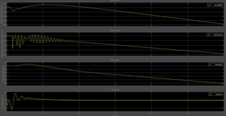
Fig. 33 shows the speed and torque parameters of the motor at 500rpm, we can see that the torque remains constant.
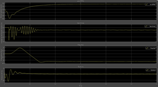
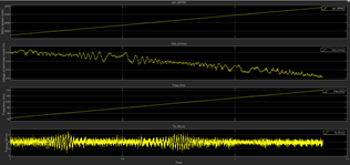
Fig. 34 shows the speed and torque parameters of the motor at 1700rpm, we can see that the torque signal remains constant.
Fig. 35 shows the speed and torque parameters of the motor at 3600rpm, we can see that the torque signal loses the desired value.
It is also observed through laboratory tests that operating the engine at a speed below 500rpm tends to stall and lose torque. Because the engine presents an error of 5% running at 200rpm and 4.05% running at 3600rpm, it is decided to define the ideal operating ranges between 500rpm and 1700rpm.
6. Conclusions
Analyzing the system in direct interaction with the engine's operating parameters, the speed range in which the tests were carried out was from 200rpm to 3600rpm, however, after evidencing an irregular behavior in torque maintenance under load conditions, a stable operating range between 500rpm to 1725rpm because the engine torque remains constant within this operating range, outside these limits we have an increase in the error that is presented in table 2 and this compromises the desired torque control.
Operating the system below 500 rpm, the error of the system compared to the validation with the physical system reaches a value of 5% and also another important problem that occurs in the physical system at speeds below 500rpm tends to lose the magnetization that results in a standstill of the motor having an output torque of zero newtons per meter, on the other hand at speeds greater than 1725 rpm the system requires a switching speed close to 18.696ms in the semiconductor block, and the torque of the machine no longer it remains constant as can be seen in Exhibit 2 with a speed of 3600 rpm.
The efficiency of the system at a speed of 1725 rpm reaches values close to 45% and the error compared to the physical system reaches a value of 4%, for this reason the mathematical model could no longer be trusted outside this limit.

