


 Inglés (pdf)
 Articulo en XML
 Referencias del artículo
 Enviar articulo por email
 Citado por SciELO
  Citado por Google
  Similares en
SciELO
Similares en
SciELO  Similares en Google
 Permalink
1. Introduction
An important consideration in an architectural project is the proper use of the finishing materials. The cladding of walls with noble materials (mainly stone) is a procedure which has been used since ancient times to give some distinction to a building. This construction system was well established. In his book De Architectura (27 BC- 23 BC), Marcus Vitruvius Pollio, [1], refers to this when describing the marble-cladded walls in the house of King Mausolus (351 BC). In Naturalis Historia (77 BC), Gaius Plinius Secundus, [2], makes reference to this same building and claims that there is a technology for cutting marble into slabs. He clearly states that the stone was cut by abrasion, as a result of the reciprocating motion of metal saws over a line on which fine-grained sand was fed. The first evidence of this cutting technology in Roman times can be found in a poem by Decimius Magnus Ausonius, [3], to the river Moselle (370 BC- 371 BC). There, he corroborates Plinius claims and points out that the sawing process is powered by a water wheel.
In 1930, during the excavation work carried out at the Temple of Artemis in Jerash (6th century AD), the archaeologists found a facility which was classified as a stone sawmill [4]. This construction includes reservoirs to collect water, a mill race with lateral walls which possibly served as a support for a hydraulic wheel (Fig. 1) and, most significantly, two limestone column drums showing evenly spaced and perfectly linear saw marks which were made using four blades. The depth and linearity of those saw marks indicate that an industrial cutting method was used. No traces have been found of the hydraulic wheel or the drive train, but there are remains of the drainage channel and the fine-grained sand used for abrasion.
Between 1969 and 1985, during archaeological excavations at Ephesus (6th century AD), members of the Österraichischen Archäologischen Institut (OAI) discovered a stone sawmill similar to the one in Jerah. This mill has walls to support the hydraulic wheel and a drainage channel. Again, the use of this construction as a sawmill is evidenced by several stone blocks showing evenly spaced and equally deep saw marks.
In the early 21st century, the sarcophagus of Marcus Aurelius Ammianos (3rd century AD) was found during excavation work at the burial grounds of Heriapolis. A raised relief on this sarcophagus shows a stone sawing machine with a hydraulic wheel. This finding, together with those made in Jerash and Ephesus, prove the existence of an industrial method for cutting stone in order to obtain slabs for cladding walls and floors in Ancient Rome.
Several studies have been conducted on these cutting systems: [5,6] proposed interpretations of the machine found in Ephesus; [7], of the Hierapolis machine; and [8], of the Jerash machine. The Römisch-Germanisches Zentralmuseum, in collaboration with the Österraichischen Archäologischen Institut, carried out a study on the Ephesus mill and went so far as to rebuild the machine in order to examine its feasibility, thus obtaining a simplified model [9].
Nonetheless, so far there is no study which has provided scientific evidence as to the operation of the stone sawing machine, its setting in motion or its working speed, and there is also no evidence of the resistance of its components. [8] claim that the builders of the stone sawmill in Jerash probably did not solve what they came to call "technical details", that is, the starting and stopping of the machine. These authors also recognize the empiric nature of their paper and the lack of specificity with regard to dimensions.
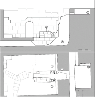
Source: The authors.
Figure 1 Reinterpretation by the authors of this paper (floor plan and elevation) of the archaeological survey [4] on the Jerash machine. 1. Location of the hydraulic wheel; 2. Supports for the shaft; 3. Reservoir.
This paper intends to deal with the problem in a more scientific manner: First, we analyse the machine found in Jerash based on the existing archaeological remains and the studies made so far; next, we propose dimensions which are consistent with the Roman age; and lastly we calculate the main components of the machine in order to check their feasability.
2. Methods
Our investigation on the Jerash machine is based on our own design, which derives from the sketches, drawings and references found in the existing papers on this topic, as mentioned in the preceding section. We have made calculations and checks on the resistance of the machine components, and we have also calculated the stresses and forces to which these components are subjected according to their location and principle of operation.
The functioning of the Jerash machine is very similar to that of other machines discovered. There was a large reservoir on a higher level than the machine. The water was discharged through a vertical channel onto a hydraulic wheel, making it turn around its shaft. The movement was transmitted to connecting rods by means of crank disks (Jerash and Ephesus) or gears (Heriapolis). The connecting rods converted the rotational motion of the shaft and the wheel into the horizontal motion of the saws. The stone blocks were cut by abrasion, as a result of the friction originated by the saws, the stone and the fine-grained sand fed to this effect.
We have conducted our investigation under these constraints. First, we created 3D models of the machine components using the software Autodesk Inventor 2020. Based on these 3D designs, we calculated the physical properties of the components as described below.
2.1. Dimensioning and modelling of the machine
The dimensioning of the machine is based on the archaeological survey [4] on the stone sawmill found in Jerash. Fig. 1 shows our reinterpretation of that survey.
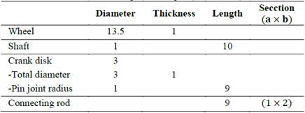
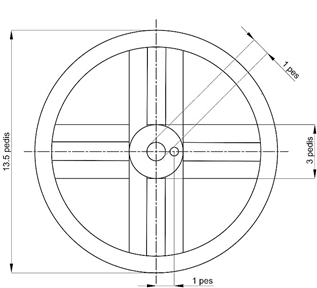
We have determined the components dimensions based on their locations and principle of operation. For this dimensioning, shown in Table 1 and Fig. 2, we have used Roman units. 1 pes = 0.296 m.
Source: The authors.
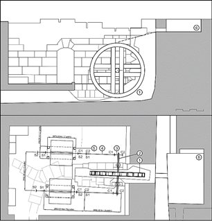
Figure 2 Dimensions and location (floor plan and elevation) of the machine components: 1. Wheel; 2. Shaft; 3. Crank disk; 4. Connecting rod; 5. Supporting structure for the saw frame; 6. Reservoir. C1 and C2 are the end positions of the connecting rod's motion; S1 and S2 are the end positions of the saw.
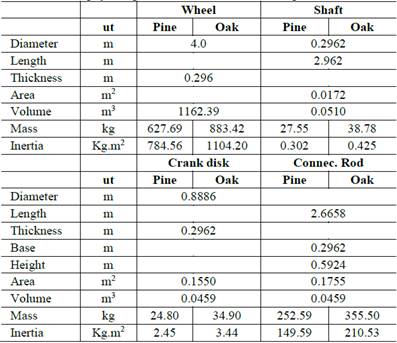
Having determined the components dimensions, we calculate the physical parameters which influence the mechanism. These parameters are shown in Table 2. As probable construction materials, we propose pinewood and oakwood. Even though the machine has been dimensioned in Roman units, the calculations and the mechanical properties of the components are expressed in metric units of the International System.
2.2. Design of the hydraulic wheel
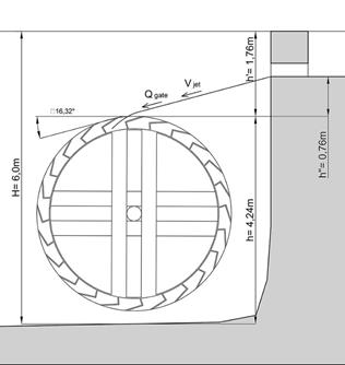
From the archaeological studies, we know that the water falls from a height of 5.1 m above the room's floor. The supporting walls for the wheel's shaft are 2.10 m high. These parameters constrain the maximum and minimum size of the hydraulic wheel. We have optimized the wheel dimensions and we have determined a diameter of 13.5 pes, corresponding to 4 m. The wheel's width is constrained by the distance between the walls which support the wheel's shaft (0.64 m). Having considered a small clearance between the wheel and the wall in order to prevent interference and unwanted contacts, we propose a width of 1 Roman foot for the wheel. (Fig. 3)
Our design of the drive components of the wheel (i.e., the distribution and number of buckets, and also the L-shape and 90º angle) is based on the suggestions made by [10,11] for the Roman hydraulic wheels of that time and the recommendations by [12] for overshot water wheels. It is known that these wheels were 80% to 90% efficient. Our proposal prioritises the accessibility for assembly and maintenance. Fig. 4, 5 show our final designs. The L-shape we propose for the buckets is effected with rectangular parts which are simple to make and assemble, for an easy maintenance of the wheel. The angle of inclination of the falling water stream remains constant during the filling of the bucket (see Fig. 6). This affects the setting in motion of the machine, as shown in the numerical analysis discussed in subsection 2.4.2.
2.3. Design of the saws
Our definition of the sawing system is based on the evidence found at the Jerash sawmill: saw marks from four parallel blades. Our design consists of a set of four saws attached to a frame which, in turn, is coupled to a connecting rod transmitting the horizontal motion. We propose a frame guiding system in order to avoid the twisting, tilting and torsion movements mentioned by [13] about this kind of ancient machines. This guiding system will be discussed in section 2.6.
The length of the blades must be that of the stones to be cut, plus the travel distance generated by the crank disk motion. The stones found in Jerash are 1.67 m and 1.51 m (aprox. 6 Roman feet) in length [14,15]. Therefore, we propose a maximum length of 8 feet for the stones to be cut. The design length of the blades is 10 feet (2.96 m).
2.4. Torque calculation
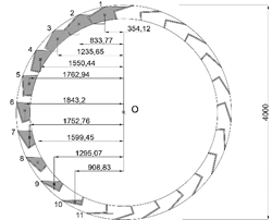
The forces generating the torque are caused by the water falling from the reservoir. According to the wheel design proposed in section 2.2, there are 10 effective buckets, which are those containing water. When a bucket is in its most advantageous position (i.e., the topmost position on the wheel, shown as bucket 1 in Fig. 4), it is filled with water to the limit of its capacity. As the wheel turns, the amount of water in the bucket gradually decreases due to the the geometric change of the effective volume (the volume capable of holding water). When it reaches the position shown as bucket 11 in Fig. 4, the bucket is already empty.
Taking this into account, we must verify whether the amount of water held by the buckets is sufficient to generate a torque. To that effect, we analyse two situations: operation in the stationary motion state of the mechanism, and operation at the starting of the machine (setting in motion).
2.4.1. Operation in the stationary motion state
When the machine is in the stationary motion state, there is a volume of water which generates a torque. This is the volume of water held by the 10 buckets which get filled and emptied owing to the wheel's geometry, as previously stated. For our calculations, and for practical purposes, we can disregard the small variations due to the filling and emptying of the buckets. The weight of the water held by the buckets generates a torque. Fig. 4 shows the length of the lever arms in the position where the wheel holds the most water.
We calculate the normal force (in Newtons, N) for each bucket. Using the horizontal distance to the vertical line of the wheel rotation axle (O), we calculate the torque generated by each bucket (in Newton × meter, N·m). Table 3 below summarizes our calculation results.
Source: The authors.
Figure 4 Parameters, in millimeters, to calculate torque in the stationary motion state of the mechanism. The area which determines each bucket's water-holding capacity is highlighted in grey colour.
Table 3 Torque values of the machine in stationary motion state. Numbers (n) correspond to the bucket numbers shown in Fig. 4.
| n | Area (mm2) | Vol (m3) | m (kg) | |
|---|---|---|---|---|
| 1 | 1.06E+05 | 2.69E-02 | 26.85 | |
| 2 | 9.52E+04 | 2.40E-02 | 24.05 | |
| 3 | 9.06E+04 | 2.29E-02 | 22.89 | |
| 4 | 8.50E+04 | 2.15E-02 | 21.47 | |
| 5 | 7.43E+04 | 1.88E-02 | 18.77 | |
| 6 | 6.50E+04 | 1.64E-02 | 16.43 | |
| 7 | 5.63E+04 | 1.42E-02 | 14.23 | |
| 8 | 4.66E+04 | 1.18E-02 | 11.77 | |
| 9 | 3.29E+04 | 8.31E-03 | 8.31 | |
| 10 | 1.38E+04 | 3.49E-03 | 3.49 | |
| n | Distance (mm) | F (N) | M (N·m) | MAcc (Nm) |
| 1 | 354.12 | 263.43 | 93.29 | 93.29 |
| 2 | 833.77 | 235.92 | 196.71 | 289.99 |
| 3 | 1235.65 | 224.57 | 277.49 | 567.48 |
| 4 | 1550.44 | 210.63 | 326.56 | 894.04 |
| 5 | 1762.94 | 184.10 | 324.55 | 1218.59 |
| 6 | 1843.2 | 161.18 | 297.09 | 1515.69 |
| 7 | 1752.76 | 139.56 | 244.62 | 1760.30 |
| 8 | 1599.45 | 115.42 | 184.60 | 1944.90 |
| 9 | 1295.07 | 81.50 | 105.54 | 2050.45 |
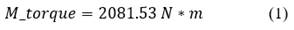
| 10 | 908.83 | 34.20 | 31.08 | 2081.53 |
Source: The authors.
In Table 3: the Area is the area shown in grey colour for each bucket in Fig. 4; Vol means the water volume held by each bucket, and m is the mass of that water volume; Distance refers to the length of the lever arm for each bucket; and F, M and MAcc are, respectively, the forces, the torques and the accumulated torques for each bucket. Thus, the torque in stationary motion state is the accumulated torque:
2.4.2. Situation at the setting in motion
A significant part of this paper is focused on calculating the torque at the setting in motion of the wheel, in order to verify the capacity of the machine to initiate motion. As already stated, none of the previous investigations about Roman stone sawmills provides a scientific analysis into the operation of the Jerash machine or any other stone sawing machine from the same period, such as the ones mentioned in the introduction.
Our calculations are based on two assumptions: first, this is a system with a single degree of freedom, and second, both the speed of the wheel and the speed of the saw frame (i.e., the piston) remain constant. Nonetheless, in the case of the setting in motion we must take into account that these speeds are not constant.
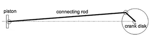
We assimilate the machine to a system with a single degree of freedom (crank disk, connecting rod and piston) shown in Fig. 3. Our model is based on the following hypotheses: a) The saw frame component is equivalent to a piston; b) The moment of inertia caused by possible misalignments of saw frame parts during cutting is negligible; c) The coupling point of the piston (sawframe) is the end of the connecting rod.
In order to set the machine in motion there are two torque-generating forces: the weight of the water held by the first 6 buckets and the impact force of the water stream on the wheel. These two forces are analysed below.
1). The weight of the water held by the first 6 buckets.
Due to the wheel's geometry, and given the starting position shown in Fig. 5, when the wheel is idle the first 6 buckets could be filled with water by the effects of gravity. The torque generated by the weight of the water held in the first 6 buckets, hereinaftercalled M_water, has already been calculated and displayed in Table 3. This torque is:
The drive resulting from the small water jets associated with the filling of the buckets has not been taken into consideration.
2). The impact force of the water stream on the wheel.
According to the previous architectural surveys mentioned in the introduction, we know that the reservoir's oulet hole is 0.32 m×0.26 m, and the room housing the wheel has got the dimensions shown in Fig. 6. These are the dimensions we will use for the following calculations.
Fig. 7 shows a graphical outline of the fluid-dynamic process and the parameters affecting the outlet speed of the water stream coming from the reservoir. This speed is defined by Bernoulli's equation:
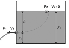
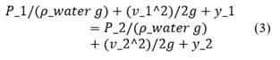
The speed at point 2 in Fig. 7 is zero, therefore: v_1 = 4.13 m / s.
The real flow rate Q_r of the water stream is obtained by multiplying the reduction coefficient 0.625 (gated outlets) times the area of the outlet hole A_(oulet hole) = 0.32m × 0.26m times the outlet speed. Thus:
Summarizing, we have the following values:
Using these values, and the dimensions and angle shown in Fig. 6 and Table 4, we can proceed to do the calculations. The speed of the water stream on hitting the wheel is 4.65 m/s. The tangential speed is 4.46 m/s. Therefore, the impact force F_𝑖𝑚𝑝𝑎𝑐𝑡 of the water stream on the wheel is given by:
Therefore, the torque M_impact generated by this impact force is given by the following equation, where r_wheel is the wheel radius:
Lastly, the torque at the setting in motion of the wheel (M_(starting )) is the result of adding the torque generated by the weight of the water held in the first 6 buckets (M_water) and the torque generated by the impact force of the water stream (M_impact).
Table 4 Values and dimensions about the reservoir.
| Height of reservoir | Height to the center of the oulet hole | Outlet speed | Area of the oulet hole | Real flow rate |
|---|---|---|---|---|
| 1 m | 0.13 m | 4.13 m/s | 0.083 m2 | 0.201 m3/s |
Source: The authors.
The consequences of the torque values obtained in subsections 2.4.1 and 2.4.2 will be discussed later in this paper.
2.5. Calculation of the friction force
2.5.1. Friction force of the shaft
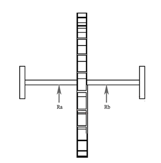
The wheel shaft has two supporting points on the stone walls of the wheel race (see Fig. 1, 2). Roman builders used to reduce friction between components by placing bronze sheets on the supports. However, we will consider the most restrictive scenario and we will use the friction coefficient between wood and stone 𝜇 wst = 0.7 for our calculations.
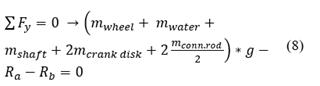
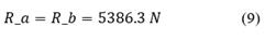
In order to model the friction force, we start by calculating the reactions at the supports (R_a and R_b). Fig. 8 shows a graphic outline. These reactions are half the weight of the group comprising: the wheel, the water, the shaft, two crank disks and two half connecting rods.
The vertical forces are cancelled out. Considering the masses of the components, we have as follows:
If we assume that the wheel is centered between the shaft supports, in the case of pinewood we have as follows:
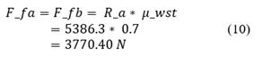
Next, we calculate the normal point friction force F_fa = F_fb at the contact points:
Lastly, we transform the normal point friction force into torsional friction torque M_ (torsional a) = M_(torsional b) because the contact is by rotational motion.
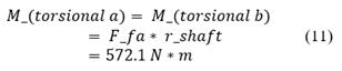
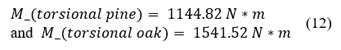
For this calculation, we can reduce the above expression to a single torsional friction torque 〖 M〗_torsional. For the proposed construction materials, we have as follows:
2.5.2. Friction force of piston, group made up by saws and saw frame (piston)
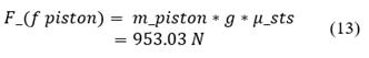
The friction force of the saw is calculated in a similar manner to the friction force of the shaft. According to our design, the mass of the piston 𝑚_𝑝𝑖𝑠𝑡𝑜𝑛 is 149.46 kg. This value results from the 3D model of the machine.
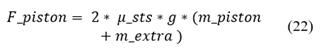
In order to obtain the friction force of the piston F_(f piston) we must use the friction coefficient between stone and sand: 𝜇sts = 0.65. By means of calculation, we obtain the following value:
2.6. Analysis of potential efficiency for the stationary motion state of the mechanism
The Jerash machine always operates at maximum speed, which is limited by the water flow rate and by the size of the water outlet hole. Next, we are going to analyse the efficiency of the power system (machine) for the stationary motion state. If the input power in stationary motion state (available power) was higher than the output power (power consumed), the machine would accelerate. The mechanism operates at maximum speed; therefore, if it accelerated, the available power would not be used to the full.
We consider that the wheel turns at constant speed and the piston follows a linear motion. We would need to calculate the power consumed by the piston at an infinite number of points of its path, where power depends on speed. In order to simplify the calculation, we will find an average speed value which is similar to the whole set of speed values for the piston. We know that
v_p = - r ϖ sin (ϖt) (1+(r cos (ϖt)) / √ (l ^ 2 - r ^ 2 〖sin〗^ 2 (ϖt))) here v_p is the linear speed of the piston, ϖ is the rotational speed of the wheel in radians per second.
In order to find an average value of the speed of the piston a value of 1 rad/s has been initially considered for ϖ.
The piston's cycle does not have negative speeds, but changes of direction. Therefore, the sum of piston's speeds is obtained by means of an integral.
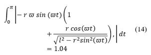
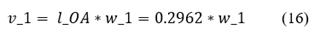
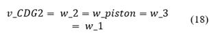
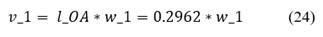
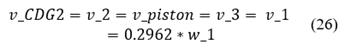
Based on this average value of 1.04 m / s, we calculate the average speed of the piston v_piston, which is as follows:

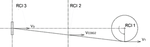
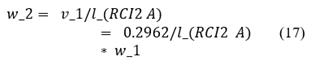
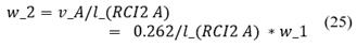
The speed of the piston at the position shown in Fig. 9 is calculated. This position is usually close to the maximum speed reached by the piston. At this point, distances l_(RCI2 A) and l_(RCI3 A) (distance to rotational center of inertia) are infinite. Therefore, the speed ratio is as follows:
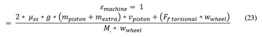
The efficiency of the machine is calculated based on these premises.
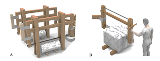
After all of the above, we know that the stone sawing machine in Jerash has an efficiency of 63.65%. According to the Overall Equipment Effectiveness (OEE) metric, this efficiency value is unacceptable. However, as already stated in section 2.3, a guiding system is needed to ensure the blades do not move out of the saw slit. This guiding can be used to improve the efficiency of the machine. We propose applying a downward force (𝑚_𝑒𝑥𝑡𝑟𝑎) on the saw blades in order to increment the friction force and thus improve the sawing effectiveness.
Source: The authors.
Figure 10 Proposal of a frame with sand containers as weights (A). Proposal with manual control of the saw frame (B). A combination of both is easy to devise.
Thus, in order to reach a 100% efficiency the following equation must be fulfilled:
Therefore, an extra mass m_extra = 240.06 kg is needed. This downward force could be applied by human effort or using weights or a combination of both. Fig. 10 shows some proposals.
2.7. Calculation of the feasibility of setting the machine in motion to start the mechanism
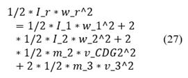
Next, we are going to mathematically determine whether the machine is able to initiate motion from standstill. In order to simplify the calculations, the mechanism is assimilated to a system with one rotation axis (wheel) having the same kinetic energy and the same power as the original. We position the mechanism in its most disadvantageous position, where the saws generate maximum opposition to the motion of the system. This happens halfway through the piston's working cycle, i.e. at one end of the piston's travel distance.
The speed ratio displayed in Fig. 9 is as follows:
The reduced inertia for w_2 = 0 is:
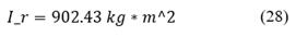
The reduced moment is:
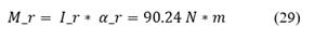
Lastly, we calculate the minimum torque M_1 required to initiate motion. In this case, the power generated by the mass of the crank disk is zero due to parallelism with the velocity vector.
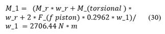
After calculation, we find that the necessary starting torque is 2706.44 N * m for pine wood, and 2511.09 N * m for oak wood.
Therefore, since the torque available for the setting in motion is 3386.93 N * m (section 2.4.2.), the machine can be started. This calculation has been made for a weighted frame. If we try to set the machine in motion without the weights, the necessary starting torque is 1795.45 N * m in case of using pinewood, and 2226.11 N * m in case of using oakwood.
2.8. Attainable cutting speed
Next, we are going to calculate the cutting speed that the machine can attain.
From section 2.4.2, we know that the real flow rate Q_r of the water stream flowing from the reservoir is: Q_r = 0.201 m^3/s = 201 kg ⁄ s
In any given moment, 10 buckets in half of the wheel are holding a total mass of water m_water = 168.25 kg (Table 3). Hence, after one revolution of the wheel, the buckets will have held twice as much water. The rotation speed of the wheel is:
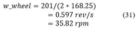
If we apply a loss coefficient of 0.8:

This speed means 57.32 saw cuts per minute, which is almost one cut per second.
2.9. Shaft resistance
Next, we are going to analyse the resistance of the shaft, which is the most critical component of the system. The saw blades can be easily replaced, so we do not believe they are so critical.
Our calculations are based on the Technical Building Code CTE-DB SE-M (2019) and on the technical specifications set out in (UNE) EN 14081-1:2016 (2016). These documents are not specific to machines, but the calculation method used for wooden components is very restrictive and applicable to our case.
Thus, using the calculation method from CTE-DB SE-M, we have obtained the following maximum permissible elasticity limits:
Next, we calculate the stresses to which the shaft is subjected, and we compare those stresses with the values that we have just obtained.
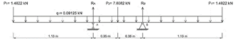
To that effect, we generate the diagram in Fig. 11, where:
Based on this data, we can calculate the bending moment and shear stress to which the shaft is subjected. The points subjected to greater stresses are the supporting points on the walls.
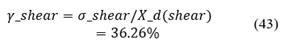
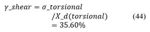
We calculate bending stress σ _ bending, torsional shear τ _ torsional and shear stress τ _ shear on these points:

We compare these values with the values previously obtained and we find that X_d(flexion) ≥ σ_bending and X_d(shear) ≥ τ_shear and X_d(torsional) ≥ τ_torsional, i.e., the shaft is resistant to all three types of stress. Since the shaft is resistant to stresses on the most disadvantageous point, we can claim that the shaft is resistant to stresses along its entire length.
It is also interesting to know the load factor of the shaft in order to ascertain the extent to which its resistance capacity is used.
Table 5 Summary of the values obtained along this work.
| ut | Pine | Oak | ||
|---|---|---|---|---|
| Shaft | Diameter | pes | 1 | |
| Length | pes | 10 | ||
| F friction | N·m | 1144.82 | 1541.52 | |
| Resist. to shear | % | 36.25 | 53.26 | |
| Resist. to bending and torsion | % | 48.12 | 48.759 | |
| Wheel | Diameter | pes | 13.5 | |
| Thickness | pes | 1 | ||
| Speed | RPM | 28.62 | ||
| Connecting rod | Section | pes | 1x2 | |
| Piston | Cuts per minute | 57.64 | ||
| Mass | kg | 149.46 | ||
| F friction | N·m | 953.02 | ||
| Stresses | M average load | kg | 240.06 | 75.09 |
| M starting required | N·m | 2706.44 | 2511.09 | |
| M starting required (no load) | N·m | 1795.43 | 2226.11 | |
| M starting available | N·m | 3386.92 | 3386.92 | |
| M starting produced by water | N·m | 3.386.93 | ||
Source: The authors.
Since the stresses take place simultaneously, we must calculate the arithmetic addition of the load factors for all points:
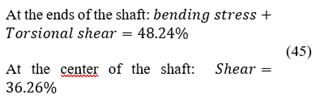
Since the most critical component of the machine does not make full use of its resistance capacity, we can conclude that, with the dimensions proposed for our model, this machine would resist the stresses to which it is subjected during operation.
3. Results
In this paper we have verified the geometric and mechanical parameters of the components making up the model that we generated for the Jerash machine based on the available archaeological data, and we have tested the operational feasibility and resistance of such components. Table 5 summarizes the results obtained.
4. Conclusions
In this paper, based on existing archaeological data, we have generated a model for the mechanism of the stone sawing machine located at the Temple of Artemis in Jerash, Jordan. We have verified the geometric and mechanical parameters of the components making up the model generated by us and we have tested the operational feasibility and resistance of such components, and we have demonstrated that this stone sawing machine was acceptably efficient.
According to our calculations, we conclude that the machine would initiate motion in any wheel position, since we have verified that it can be started in the most disadvantageous position. This is true for both proposed construction materials: pinewood and oakwood.
We have demonstrated that the Jerash machine made one cut per second and operated at constant maximum speed, with the only limitation of the water stream flow rate.
Our model shows that this Roman machine on its own did not make full use of the power it was able to generate from the available feeding flow rate. In order to aid cutting and increase efficiency, a downward force had to be applied on the saw frame. This downward force could be in the form of weights which may be placed and changed depending on each cutting job requirements (Fig. 10-A). However, human effort could also be used to this end. Given the cutting frequency resulting from our model (1 cut per second), some kind of guiding system is needed to ensure the blades do not move out of the saw slit. Since the machine requires an operator, it is very likely that he applied the necessary downward force to make the maximum possible use of the machine's effective power. The frame probably had handles to that effect. (Fig. 10-B).
With regard to the choice of materials, our results suggest that pinewood would be preferable, since:
The average degree of utilization of the sawing power is considerably greater with a pinewood machine than with an oakwood machine.
The setting in motion with empty buckets requires less torque in the case of pinewood, so the machine would start more easily and the acceleration would be faster.
With regard to the resistance of the connecting rods and the shaft, the machine can better endure stress if pinewood is used as building material.
Based on physical calculations, mechanism theory and fluid-mechanical theory, we conclude that the ancient stone sawing machine located at the Temple of Artemis in Jerash was capable of operation with the dimensions used for our model, which were also the design dimensions used by Roman engineers.

