


 English (pdf)
 Article in xml format
 Article references
 Send this article by e-mail
 Cited by SciELO
  Cited by Google
  Similars in
SciELO
Similars in
SciELO  Similars in Google
 Permalink
Introduction
Transverse zones comprise tectonic structures parallel or oblique to the shortening trend (Butler, 1982); they are located transversely to the fold and thrust belt and connect strike-parallel frontal ramps. The primary surface geological features indicating transverse zones are the interruptions in faults and folds along the strike, folds with irregular plunge directions, abrupt changes in the longitudinal wavelength of folds, and geomorphological discontinuities (Dixon and Spratt, 2004; Pohn, 2000; Thomas, 1990). However, according to Aridhi et al. (2011), these surface characteristics can be misidentified or misinterpreted during mapping due to strike-slip fault movements. Nonetheless, Calassou et al. (1993) described several patterns observed in thrust faults to identify the parameters that generate a transfer zone.
Transverse zones include lateral ramps, transverse faults, and transfer zones (Thomas, 1990). These zones generate several sets of thrusts, and the extent of shortening of these thrusts is comparable to the displacement of the detachment (Kwon and Mitra, 2006). The origin and evolution of transverse structures include (i) basement faults, (ii) mechanical and stratigraphic differences along the strike, and (iii) a decrease in the displacement along the strike of the primary structure (Dixon and Spratt, 2004; McClay, 1992; Pohn, 2000; Thomas, 1990).
Lateral ramps are inherited tectonic structures that define basin geometry before shortening and are generated due to abrupt stratigraphic changes or pre- existing faults in the axial zones of the fold and thrust belts and mountain ranges (Cook and Thomas, 2009; Kwon and Mitra, 2006, 2012). Previous research regarding lateral ramps has focused on the dips of these ramps. For instance, McClay (1992) indicated that lateral ramps are defined by dip angles of 10°-30?, whereas Dixon and Spratt (2004) proposed that lateral ramps with angles of 10?-90?, suggesting that vertical, lateral ramps are tear faults.
This work aims to determine distinct surface and subsurface structures and geometries related to lateral ramps in the different zones of the fold and thrust belts lateral ramps. We considered three dip angles (30, 45, and 60) of the lateral ramp, as suggested by Dixon and Spratt (2004).
Methods and assumptions
The experimental designs comprise a lateral ramp linked to two frontal ramps, simulating inherited structures or pre-existing basin anisotropies. A rigid block and quartz sand simulate the mechanical discontinuity between the basement and the sedimentary sequence. The rigid block is static and represents the basement anisotropies; this assumption implies no plastic or elastic behavior during deformation (Rosas et al., 2017). Frontal ramps of the rigid block are named fore- frontal ramp and the back-frontal ramp (Figure 1).
The dry quartz sand used in this model was sorted via mechanical sieving; this sand features grain sizes of approximately 150-200 µm (fine-grained) and is sub-rounded and homogeneous (well-sorted). These properties are in-line with the parameters reported by Dooley and Schreurs (2012) for an analogue model. Based on the dynamic scaling theory, quartz sand is a suitable material for representing brittle crustal rocks, assuming Mohr-Coulomb-type brittle behavior (Dooley and Schreurs, 2012; Graveleau et al., 2012; Hubbert, 1937; Schellart and Strak, 2016).
The ratio of length parameter (L) is 10-5 (1 cm:1 km) (Gomes, 2013; Hubbert, 1937; Schellart, 2000; Schreurs et al., 2016). Dynamic scaling parameters are i) the internal friction angle (Φ), of 29.6?derived from the angle of repose (φrep) (Solaque and Lizcano, 2008); and ii) cohesion (C), in normal gravity conditions the dry quartz sand represent the cohesion of the upper crust, which has a cohesion force of approximately 40 MPa. Since the general stress (σ) equation is σ=L*ρ*g, where ρ is density, and the ratio of ρ and g in the model is approximately 1 (Byerlee, 1978; Schellart, 2000; Schreurs et al., 2016). If Φ ~30 and C is ~250 Pa, Φ and C are appropriate for implementing analogue models (Bureau et al., 2014; Schellart and Strak, 2016).
Granular materials can be scaled appropriately considering only Φ and C because these values are directly associated with parameters such as the density, size, and shape of the granular material, without regard to the time scale.
Thirty-six (36) analogue models were carried out, for three different dips 30?, 45°, and 60?, twelve (12) models for each ramp angle, in a subduction-type sandbox with normal field gravity, which hinders the scaling of stresses (Koyi, 1997) and rigid blocks located above the velocity discontinuity zone (Figure 1). This sandbox or table consists of two lateral glass walls and a frictionless paper sheet at the base. The paper sheet moves through one roller located in the velocity-discontinuity zone of the table; this roller is driven by a mechanical pulley system (Figure 1), and the average displacement velocity of the paper sheet was 0.05 cm/s. Nevertheless, the deformation of sand does not depend on velocity because it follows a Coulomb-like behavior. Paper properties were verified; according to Davis et al. (1983), the friction coefficient was 0.43 and considered suitable because friction coefficients less than 0.46 are required for analogue models (Graveleau et al., 2012).
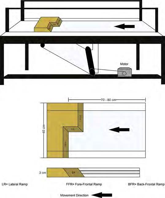
Figure 1 Scheme of subduction-type table. The figure shows Top and lateral views of the general configuration, considering a system involving lateral and frontal ramps. The top view shows the disposition of a wood block, where are differenced each ramp. The lateral view shows the pulley system used to displace the base of paper; moreover, it shows the two vertical glasses on the table.
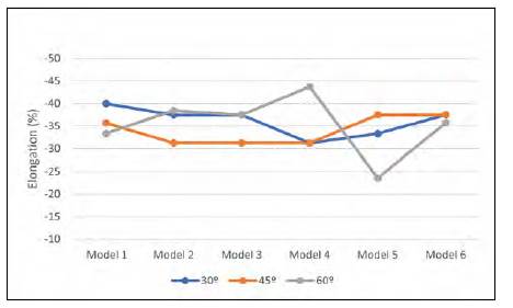
Each experimental design involved an initial vertical thickness of 3 cm and five horizontal layers. The first layer was composed of yellow quartz sand with a thickness of 1 cm, whereas the remaining four layers were interbedded layers of black-dyed quartz sand (0.2 cm) and yellow quartz sand (0.8 cm). Among the 36 models, 18 models were measured along the shortened axis (Table 1) and recorded photographically. The stretch (s) and elongation (e) factors were determined, regard to the fore-frontal ramp (Table 1) and show no tendencies between experiments (Figure 2). The deformation observed in each experiment was analyzed from three distinct perspectives: top view, transverse section, and longitudinal section.
Table 1 Calculation of the shortening and lateral deformation (stretching (s) and elongation (e)) based on final and initial lengths.
| ID experiment (dip angle-serie) | Li (cm) | Lf (cm) | ΔL (cm) | S | e (%) |
|---|---|---|---|---|---|
| 30-01 | 75 | 45 | -30 | 0.6 | -40 |
| 30-02 | 80 | 50 | -30 | 0.62 | -37.5 |
| 30-03 | 80 | 50 | -30 | 0.62 | -37.5 |
| 30-04 | 80 | 55 | -25 | 0.68 | -31.25 |
| 30-05 | 75 | 50 | -25 | 0.66 | -33.33 |
| 30-06 | 80 | 50 | -30 | 0.62 | -37.5 |
| 45-01 | 70 | 45 | -25 | 0.64 | -35.71 |
| 45-02 | 80 | 55 | -25 | 0.68 | -31.25 |
| 45-03 | 80 | 55 | -25 | 0.68 | -31.25 |
| 45-04 | 80 | 55 | -25 | 0.68 | -31.25 |
| 45-05 | 80 | 50 | -30 | 0.62 | -37.5 |
| 45-06 | 80 | 50 | -30 | 0.62 | -37.5 |
| 60-01 | 75 | 50 | -25 | 0.66 | -33.33 |
| 60-02 | 65 | 40 | -25 | 0.61 | -38.46 |
| 60-03 | 80 | 50 | -30 | 0.62 | -37.5 |
| 60-04 | 80 | 45 | -35 | 0.56 | -43.75 |
| 60-05 | 85 | 65 | -20 | 0.76 | -23.52 |
| 60-06 | 70 | 45 | -25 | 0.64 | -35.71 |
Results
Lateral ramps with a dip of 30°
In the experiment 30-05, the progressive shortening is presented sequentially in Figures 3A-2F. Once the shortening reached 5 cm, the first thrust fault in each frontal ramp and several related back-thrust faults were generated, which led to the formation of pop-up structures and anticlines parallel to the frontal ramps. Moreover, these structures were interrupted by lateral ramp structures. With an increase in the shortening, new back-thrust faults were generated in each frontal ramp, following a direction opposite to that of motion; consequently, the first thrust fault became convex (Figures 3C-2E). Additionally, anticlines plunged, and hinge axes bent over the lateral ramp. This analogue model reached the final stage after 25 cm of shortening, equivalent to 33% (Table 1) (Figure 3F). The structures in the final stage were main convex thrust faults. In this setting, for each frontal ramp, eleven (11) faults were generated, and the back-thrust spaced at 1-cm intervals.
Transverse sections, i.e., sections parallel to the motion, show similar structures in both frontal ramps because deformation was initially concentrated in main thrust faults, stacking in each ramp. These models feature fewer back-thrust faults related to the back-frontal ramp than those related to the fore-frontal ramp and an average ratio of 12:10 (fore-frontal ramp: back- frontal ramp) (Figures 4A, 4D). These back-thrust faults exhibited high angles (40?-70?) associated with the displacement of structures through the ramp with an increase in deformation (Figure 4).
The transverse sections in the lateral ramp exhibited significant structural complexity concerning the transverse sections on the frontal ramp. Three thrusts occurred at the fore-frontal ramp, which reduced the number of back-thrust faults relative to the back- frontal ramp. This structural setting and several blind back-thrusts define a triangular zone (Figure 4C). Additionally, these transverse sections were less influenced by the back-thrust faults from the back- frontal ramp when the sections were closer to the fore- frontal ramp (on top of the lateral ramp), until only the main thrust fault of the back-frontal ramp remained (Figure 4C).
Longitudinal sections, i.e., sections perpendicular to the motion, show irregularities in layer continuity for both frontal ramps, owing to the back-thrusts (Figure 5). Moreover, these layers evidence a change of the monocline inclinations in the frontal ramp. The main structures observed in these sections were reverse faults located over the lateral ramp, as highlighted with red lines (Figure 5). These reverse faults exhibited high angles (~70?) on the base of the lateral ramp, and the angles declined near the surface (~45?). These reverse faults have detachments in the horizontal top surface of the rigid block.
Lateral ramps with a dip of 45°
Once the shortening reached 7.5% (45-05), the first thrust and two back-thrust were identified from the top view. These faults generated significant anticlines amid the pop-up structures associated with each ramp (Figure 3H). These structures were preserved at the final stage with a shortening of 37.5%, and the hinge axes of the anticlines plunge toward the lateral ramp (Figure 3L) (Table 1). Furthermore, the main thrust fault in each ramp had a convex shape. In this model, ten (10) back-thrust are related to fore-frontal and nine back-thrust related to back-frontal ramps. In the top view, fault separation is approximately ~1.5 cm.
In the final stage of the displayed analogue model (45- 05), for each frontal ramp, the transverse sections show a thrust-fault stacking; this generated a fold, similar to a fault bend fold. In these sections, there are more back-thrust faults in the fore-frontal ramp than in the back-frontal ramp. On average, the relationship among the number of back-thrust faults in the frontal ramps for each experiment was similar (10:9). Back-thrust faults exhibited dips of 30?-60?. Imbricate systems produce backward faults with the higher angles (Figures 4A- 4H).
The transverse sections located in the lateral ramp enabled us to distinguish a triangular zone consisting of three thrust faults and several back-thrust faults from the fore-frontal ramp and the fore-frontal ramp, respectively (Figure 4G: C6, C7, and C8). The triangular zone was not observed in the sections near the fore-frontal ramp because of the back-thrust faults from the back-frontal ramp due to anticline stacking. Back-thrust faults from the fore-frontal ramp in sections C6-C9 reached angles of ~90?, and several segments of these faults appeared inverted, similar to the observations in normal faults (Figure 4G: C6 and C7).
The longitudinal sections revealed discontinuity layers due to the irregular shape of the back-thrust plane from each frontal ramp, as observed in the experiment 45-04 (Figure 5B). The reverse faults are dipping in the opposite direction to the lateral ramp (red lines) in the longitudinal sections (Figure 5B). These faults featured high angles of 35? at the center of the lateral ramp; however, these angles reached 45? at the frontal ramps.
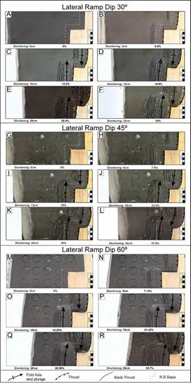
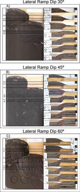
Figure 3 A-F. Progressive deformation in the first experiment; G-L. Progressive deformation in the second experiment; and M-R. Progressive deformation in the third experiment. These images evidence the appearance of different structures at each shortening stage.
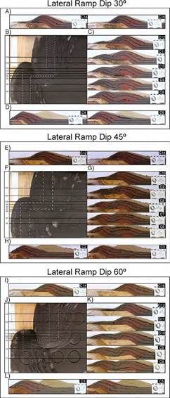
Figure 4 A-D. Transverse sections in the first experiment; E-H. Transverse sections in the second experiment; and I-L. Transverse sections in the third experiment. A, E, I. transverse section of the fore-frontal ramp; B, F, J. top view indicating the location of transverse sections; C, G, K. transverse section of the lateral ramp; and d, h, l) transverse section of the back-frontal ramp.
Lateral ramps with a dip of 60°
The top view of the experiment 60-03 indicated shortening stages once motion started, similar to the previous experimental setting. When the shortening reached 7.14%, one thrust fault and a pair of back- thrust faults occurred at each frontal ramp (Figure 3N). With an increase in shortening, additional back-thrust appeared parallel to the frontal ramps, separated by approximately 2 cm. The hinge axes of the anticlines generated between the thrust-fault stacking and back- thrust faults evidenced an apparent plunge. This deformation tendency continued until the final stage of the experiment, which allowed us to observe the convex shape of the main thrust faults (Figures 3N-3R). In the final stage, the top view (Figure 3R) indicated 11 back-thrust faults in the fore-frontal ramp and ten (10) back-thrust faults in the back-frontal ramp.
During the final stage of experiment 60-03, the transverse sections revealed one main thrust-fault stacking over each frontal ramp; this fault and the back-thrust faults constitute the pop-up structures and anticline in each ramp. Moreover, the ratio of fore-frontal and back- frontal ramps in the back-thrust faults was 10:9. Thus, an imbricated fault system was formed (Figures 4I, 4L). The first back-thrust generated close to each frontal ramp and reached dips of approximately 90?.
The notable structures in the transverse sections over the intersection between the fore-frontal ramp and the lateral ramp were two thrust faults with dips of 30°- 45?, which generated small folds in the frontal flank of the anticline. Furthermore, these reverse faults and back-thrust faults of the back-frontal ramp constitute a triangle zone with several blind faults (Figure 4K). Transverse sections C9 and C10 (Figure 4K) are located over the lateral ramp, closer to the fore-frontal ramp; these sections evidenced the loss of deformation in the back-frontal ramp because the back-thrust faults of this frontal ramp disappeared.
The longitudinal sections of the experiment 60- 05 suggest a discontinuity of black layers due to back-thrust in each frontal ramp (Figure 5C). The longitudinal sections demonstrate reverse faults on the lateral ramp, which feature an average dip of 35?. The number of these reverse faults varied for sections C7- C17 (Figure 5C). Moreover, normal faults are evident in the sections over the corner between the fore-frontal ramp and the lateral ramp, i.e., in sections C8 and C9. These faults show dips of 80°-90? and have the same vergence as the lateral ramp (Figure 5C).
Discussion
The three tested experimental settings (30?, 45?, and 60? inclinations) revealed minor differences and developed similar structures and geometries during progressive deformation. Here, we describe these similarities and differences from the perspective of each view: top view, longitudinal section, and transverse section.
In top view, the stacking thrust faults were the primary structures generated in each frontal ramp. Although these thrust faults are convex, these shapes were more notable in the back-frontal ramp. Back-thrust sequences at the front of each frontal ramp were observed in each setting; these sequences feature similar average structures separated ~2cm. Two Anticline structures were associated with each frontal ramps, with plunges in opposite directions over the lateral ramp.
These anticlines indicate dextral shear in these analogue models; even the back-thrust faults generated in frontal ramps featured identical flexure due to velocity differences at the two sides of the lateral ramp. However, based on the homogenous displacement along the strike of the main structures, which is similar for each experiment (Table 1; Figures 2 and 3), and the lack of deformation in the transverse direction of surface movement, it was concluded that it is unnecessary to consider deflection along the transport direction over the map view when the possible lateral ramp is below the base level of deformed rock. This deflection could be observed in deep zones at the same elevation as the lateral ramp, as suggested in previous studies (Apotria et al., 1992; Apotria, 1995; Wilkerson et al., 1992), when oblique anisotropies existed in the basement. However, these studies evaluated different structures as oblique ramps with vergence and vertical- lateral ramps, in which deflections were not defined. Therefore, it could be possible to depreciate the deflection of movement in the deep zones.
Furthermore, the clockwise rotations of the vertical axis in the structures are highlighted in Figure 6A, considering the movement of the rigid block and sand (denoted by a dashed green line) and the main thrust fault from each frontal ramp. Based on structural and paleomagnetic data, Bayona et al. (2003) proposed clockwise rotation around the transverse zone and counterclockwise rotations outside this zone within the Appalachian thrust belt of Georgia and Alabama.
This area of the Appalachian thrust belt has a structural setting similar to the ramp setup. Therefore, our experiment primarily demonstrates the rotation caused by the influence of the lateral ramp.
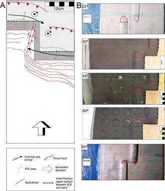
Figure 6 Top view of the structural analysis: A. Schematic based on the results of each model, this scheme shows the main structures identified in the models (thrust fault, back-thrust fault, and folds) and faults parallel to the lateral ramp. Dashed green lines mark the initial contact between sand and the top of the rigid block to highlight the rotation identified in models. B. Comparison of the results with those reported by Dixon and Spratt (2004), where the plunge of folds are associated with the dip of the lateral ramp.
In the top view, the main difference between the three experiment settings was the geometry of the anticlines close to the lateral ramp (Figure 6B). The anticlines in each model show a characteristic plunge that decreases sequentially from the third experiment (60?) to the first (30?), as evidenced by the length and shape of the wedge (Figure 6B). Considering this analysis, the analogue models in this study complement Dixon and Spratt (2004), where wedges were located in the transverse zone between two frontal ramps, when the lateral ramp dip was 22? and diminished when the dip was 90?, because the slope was approximately equal to 90? (Figure 6B).
This observation confirms that plunges are strictly associated with the lateral ramp (De Lamotte and Guézou, 1996; Wilkerson et al., 2002) and also affects the fault strike. With a relationship between the inclination of the lateral ramp and plunge, vertical, lateral ramps imply a high plunge.
Our analogue models confirm two guidelines to recognize lateral ramps on the surface (Pohn, 2000): i) the abrupt change in wavelength or the end of folds through the strike, and ii) the change in the frequency of mapped faults, including the increase in the distance from one back-thrust fault to another when the dip of the ramp is higher.
The longitudinal sections confirm that monoclines associated with the plunge of each anticline and dip angles of the lateral ramp (Figure 7B), thereby complementing the top view analysis over the wedge shape (Figure 7B).
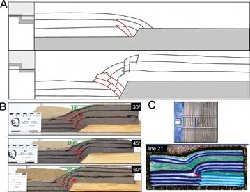
Figure 7 Structural analysis of the longitudinal sections: A. Schematic model where reverse faults follow opposite vergence to the lateral ramp and the normal faults identified in the third experiment. B. Comparison of the results of this study as a function of the lateral ramp dip and C. Results for the ramp of dip 90? reported by Dixon and Spratt (2004).
Nevertheless, the main structural characteristic observed in these sections is that reverse faults have an opposite dip direction to the lateral ramp and a smaller angle over the ramp as well as an increase in the lateral ramp dip; this establishes an inverse relationship between the lateral ramp dip and the generated reverse faults (Figure 7B). These structures separate the faults into thrust faults, and back-thrust was generated parallel to the frontal ramps. In contrast to the experiments conducted by Dixon and Spratt (2004) using lateral ramps with dips of 90? and 22? where these reverse faults show low angles and were related to the lateral end of the main thrust faults at each frontal ramp (Figure 7C). Faults in the transverse zone of our experiments are associated with surface fractures and the plunge of anticlines, which indicates a change in structural relief; these faults evidence an oblique displacement, considering the right lateral displacement inferred from the top views and the vertical displacement in the longitudinal sections. However, this observation is opposite to analogue models reported by Calassou et al. (1993), where faults follow an opposite vergence if the fault detached from the fore-frontal ramp and follow a similar vergence in the back-frontal ramp (Figures 6A, 7A).
In the third experimental setting, normal faults located in the fore-frontal ramp follow the lateral ramp trends.
These normal faults are probably associated with the gravitational extension caused by the plunge of the anticline (Figures 7A, 7B). Normal faults are associated with vertical lateral ramps due to the stability or the friction coefficient in the upper crust.
Finally, the transverse sections indicate that the structural setting is similar in both frontal ramps, revealing one main stacking thrust fault with vergence along the direction of movement and a sequence of back-thrust faults. The fore-frontal ramp featured other back-thrust faults and had more than one thrust fault at several instances (Figure 8D). Multiple thrust faults observed in the lateral ramp suggests a propagation of the structures in the frontal ramps over the lateral ramp. We consider these apparent thrust faults as the oblique faults evidenced in longitudinal sections. Thrust faults and blind back-thrust faults in the back- frontal ramp, and oblique faults in the lateral ramp, defined A triangle zone (Figure 8C). At the top of the lateral ramp, the geometry changes gradually due to back-thrust in the fore-frontal ramp.
In the back-frontal, ramp structures disappear with a single stacking thrust fault observed. The lateral continuity in the back-frontal ramp was interrupted by oblique faults, where the shortening was sub-parallel to the lateral ramp (Figure 8B).
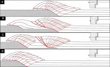
Figure 8 Schematic based on the transverse sections of each model, where are marked with red lines thrust faults and back-thrust faults: A. schematic of the front-frontal ramp, B. Schematic of the lateral ramp near the front-frontal ramp, C. schematic of the lateral ramp near the back-frontal ramp, and D. Schematic model of the back-frontal ramp.
Our results are comparable with the structures observed in the Eastern Cordillera of Colombia and the Eastern Cordillera of northern Argentina, where structures vary in terms of the strike, abrupt interruptions, and reverse faults semi-parallel to lateral ramps, associated with the pattern of pre-deformational sedimentary thickness, which generated lateral or oblique ramps. The lateral ramps of Argentina are located to the south and north with strike E-W (Mon et al., 2005) (Figure 9A) and in Colombia in the central zone (García and Jiménez, 2016) (Figure 9C). We compared these structural settings with the lateral ramp proposed by Araque-Gómez and Otero-Ramírez (2016) for the western flank of the Eastern Cordillera, Colombia, which only exhibits a flexure in the main fault. Araque-Gómez and Otero-Ramírez (2016) proposed a transverse zone length of around 3.5 km. We assumed that our analogue models were suitable, and the length of the lateral ramp was considerable to simulate these of structures.
The longitudinal section in the Ardennes Variscan fold and the thrust belt implies a reverse fault with a high angle, with opposite vergence to the lateral ramp, and a back-thrust fault parallel to the frontal ramp (Lacquement et al., 2005); this is in agreement with Dixon and Spratt (2004). The Leamington transverse zone (Kwon and Mitra, 2012) in the Sevier fold and thrust belt suggests that connected faults have the same relationship as the previous example. In the map view, a reverse fault is parallel to the lateral ramp (Kwon and Mitra, 2012) with a similar convex shape associated with the main stacking thrust faults observed in our experiments. Although interpretations of the back-thrust faults can be adjusted, our results indicate that these structures are independent faults, depending on their high dips (Figure 9B). Thus, our results prove that the fault strike changed gradually and that the faults semi-parallel to the lateral ramp were different structures compared to the back-thrust faults.
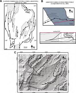
Figure 9 Examples of natural transverse zones with lateral ramps: A. Structural map of the north of eastern Cordillera, Central Andes of Argentina, indicating two lateral or oblique ramps associated with Rearte Fault in the south and Castillejo Fault in the north (modified from Mon et al., 2005). B. Longitudinal section of the Ardennes Variscan fold-thrust fault over a lateral ramp of the Meuse Valley Recess, indicating the interpretation of the Givet back-thrust (modified from Lacquement et al., 2005). C. DEM of the Zipaquira Anticline in the Eastern Cordillera of Colombia. The Zipaquira Anticline is defined by two different folds separated by a transverse fault (García and Jiménez, 2016).
Conclusions
We identified new indicators of the presence of lateral ramps in underground areas and also corroborated previous results. In this setup, we have like boundary condition a staking thrust fault in each ramp, which acquires a convex shape. The back-thrust sequences were observed in each model and typically show more faults in the fore-frontal ramp.
These back thrusts exhibited minor displacements, an essential new indicator to distinguish areas with strike- slip displacements and those dominated by lateral ramps.
Dextral shear in the lateral ramp was associated with the velocity difference between two sides of the lateral ramp, which corroborated the results of prior approaches suggesting that the displacement of particles primarily occurs along the backward direction in the fore-frontal ramp. Around the lateral ramp area, clockwise rotations are associated with the dextral shear zone. However, it was not necessary to consider the deflection in the movement direction, as observed by previous research, owing to the lack of conclusive proofs.
Faults sub-parallel to the lateral ramp are oblique reverse faults with opposite dip direction of the lateral ramp. These oblique faults cloud indicate the lateral ramp inclinations because low angle oblique faults are associated to vertical lateral ramps. The dip of the structures is an essential difference in the experimental settings; the plunges of anticlines are proportional to the dip of the lateral ramp. When the lateral ramp inclinations exceed 60?, plunges are high and generate normal faults due to the friction coefficient.

