


 Inglês (pdf)
 Artigo em XML
 Referências do artigo
 Enviar este artigo por email
 Citado por SciELO
  Citado por Google
  Similares em
SciELO
Similares em
SciELO  Similares em Google
 Permalink
Introduction
The sugarcane processing industry produces bagasse as a by-product that persists after the crushing of cane (Raj & Stalin, 2016)(Shrivastav & Hussain, 2013)(Ravichandran, Kavinkumar, Kumar, Prasanth, & Ramkumar, 2017). Around 12% of sugarcane mass becomes bagasse that contains moisture and a small amount of soluble solids (Gilberd & Sheehan, 2013). Bagasse can be a useful waste for co-generation plants such as for power production (To, Seebaluck, & Leach, 2018) (Silva, Schlindwein, Vasconcelos, & Corréa, 2017). With increasing pressure to find alternative energy generation to that of traditional fossil fuels, an increase in efficiency of the burning of bagasse for energy generation will be beneficial not only for the sugarcane industry but also for society in general (To et al., 2018)(Silva et al., 2017). Moisture is a key factor that affects the efficiency of the burning of bagasse (Abdalla, Hassan, & Mansour, 2018) wherefore, 26 kg/s of bagasse flows with constant rate (proposed design(Shanmukharadhya & Sudhakar, 2007). A proper industrial scale improved design of the bagasse drying system is essential to ensure the resolution of such a problem.
To design a new industrial bagasse drying system, information from a company that can produce 2.16 million tons of crushed cane and produces 63 MW of power from its co-generation plant was considered. Its bagasse has been used for electricity generation since 2005 and feeds into the Australian power grid for many years. The current operation sees on average 60 tph of bagasse being consumed by a boiler at roughly 48% moisture content. By drying the bagasse (to an average of 30%), the efficiency of the boiler can be increased, resulting in greater profits, and a sustainable system. This paper investigates the designing considerations of an improved bagasse drying system to reduce the moisture content of bagasse fed into the boiler to increase efficiency.
A method of increasing this efficiency is to pre- dry the bagasse. It has been demonstrated that there can be up to an 18% reduction in bagasse use by the boiler with the assistance of pre-drying (Gilberd & Sheehan, 2013). To achieve these aims, an improved bagasse dryer design is needed that will increase the operational efficiency of the boiler, and in turn, produce a higher return on each tonne of cane. The design had to meet the company’s requirements. To ensure compliance, the company standard requirements were reviewed to meet all relevant design standards and regulations. Also, the design of a bagasse drying system has been extensively studied from different sources by a team of researchers and the process was well documented and largely parameterized to decide on our design.
Using the required knowledge from the review study, this work studies the design of a bagasse drying system and parts specification that will reduce the amount of moisture in bagasse from approximately 48% to 30% following several subsystem analyses. All the important subsystem components are be studied and identified.
Materials and Methods
The design and performance analysis of the bagasse dryer system was conducted with the standard design compliancy of the Australian company. In the first steps of the work, a risk management study was conducted as specified in AS/NZS ISO 31000:2009 Risk Management - Principles and Guidelines (AS/NZS ISO 31000:2009). The bagasse drying system’s installation, operation, and maintenance work requirements were broken down into their logical categories and exposures. The potential risks and related hazards were determined in a brainstorming workshop held by relevant professionals, along with representatives from the company. While completing the risk assessment, factors with potential sustainable development impact were also considered.
Using the “As low as reasonably possiblé’ (ALARP) system (Yasseri, 2013) each risk was reviewed and alternate methods or additional controls were identified as per the hierarchy of controls until an effective and practicable level of risk reduction was achieved. To develop the most appropriate drying system for the sugar mill, design requirements were followed to make three major design components as follows-Inlet and outlet feeders to introduce and remove the bagasse from the system,
Drying tube to remove moisture from the bagasse,
Dry scrubber (cyclone) to separate the dry bagasse from the flue gas.
The proposed bagasse drying system should not physically interfere with the existing plant. The available space for the dryer system was a 6*6 m pad area with a height limit of 25 m. The new dryer was made compatible with the existing plant using the same kind of fittings, pipe diameters etc. Enough care was taken to avoid any accessibility problem of mobile equipment within the existing plant. For simplicity of the design and analysis, the coupling between the flue gas line (boiler exits), and the dryer, the cyclone gas outlet, and the stack is not included in the design. We also excluded the required power supply to the bagasse drying system, and cleaning of the flue gas before being introduced to the dryer is also excluded from the design.
Boiler and bagasse information
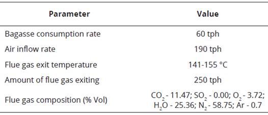
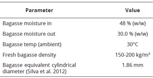
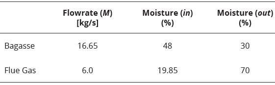
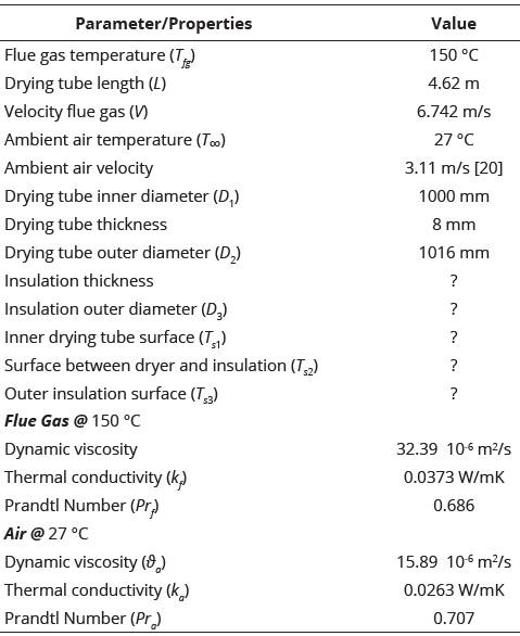
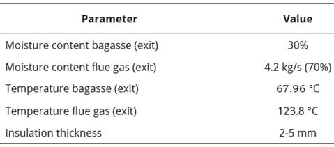
The proposed dryer must satisfy the capability of the boiler and bagasse is required to dry before feeding into the boiler. The essential boiler information (Table 1) has been supplied by the company concerning the target boiler. The information regarding bagasse (Table 2) is sourced or provided from the sugar mill.
Dryer design parameters and specifications
Feeder selection
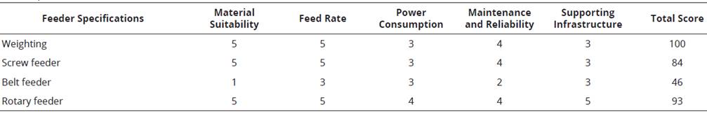
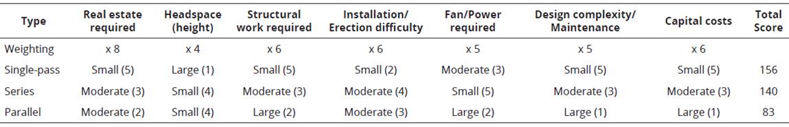
After consultation with the company about the importance of design aspects and design requirements, a weighted decision matrix (Ouye, Facility Technics Facility Management Consulting) was devised for selecting the best- fitted feeder for the dryer design. The rotary feeder has found as the most appropriate choice for both the inlet and outlet feeders (Table 3). Using the boiler and bagasse information (Table 1-2), the required volumetric feed can be calculated as ~0.111 m3/s.
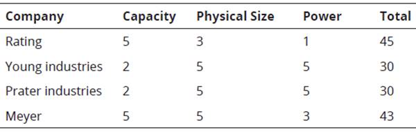
It should be noted that the bagasse is a relatively light density material and at times due to compaction, flows in a sluggish manner. As such, the fill capacity of the bagasse in the rotor pockets is approximately 60-80%. The worst-case scenario (60%) should be considered to identify the best rotary feeder model that could supply the required feed rate of 0.111 m3/s. From the available Meyer rotary feeder types (Company Catalogue, Smoot Inc, 2014), a feeder is available to handle bagasse demand of 36 x 36 inch at 20 RPM (Company Catalogue, Smoot Inc, 2014), capable of transporting 0.113 m3/s when our design requires 0.111 m3/s (Table 4). Considering gear ration of 1:50 between the shaft and the final drive on the motor and 90% efficiency, the required amount of motor power for the selected feeder is 2 hp and the outlet feeder can be specified as the same feeder as the primary feeder (Meyer 36 x 36 inches rotary feeder (Company Catalogue, Smoot Inc, 2014).
Dryer
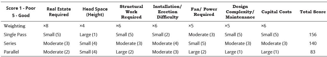
Due to the limited space available at the involved sugar mill, the short residence time required to meet the 60 tph throughput (Table 1-2), and the nature of bagasse (fibrous), a flash dryer (or pneumatic dryer) system (Sosa-Arnao & Nebra, 2009)(Borde & Levy, 2006) would be the most appropriate. The hot gas stream, (in this case, flue gas from the boiler) can be used to evaporate the moisture from the bagasse (solid). Following the drying process, separation via a dry scrubber can be implemented. The appropriateness of the type of flash dryer was determined using a weighted decision matrix (Ouye, Facility Technics Facility Management Consulting) (Table 5). and it was determined that the single-pass circular drying tube is the most appropriate for the design that was later approved by engineers from the company with dimensions.
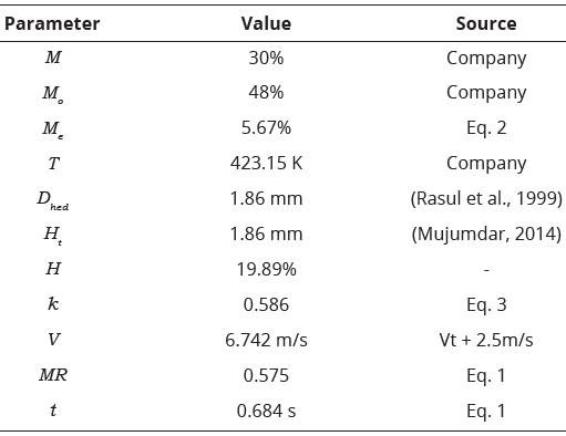
A thin-layer drying model (Vijayaraj, Saravanan, & Renganarayanan, 2007) was used and it was found that the Page model (Eq. 1) is the most appropriate for the modeling of bagasse drying (Gilberd & Sheehan, 2013) (Vijayaraj et al., 2007) (Polanco, Kochergin, & Alvarez, 2013) The equilibrium moisture of bagasse can be calculated by the following equation-

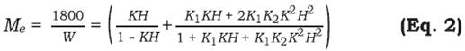
Where, M = material moisture content (%), M e = equilibrium moisture content in % dry basis, M o = initial moisture content (%), k = drying rate coefficient (s-1), n = empirical constant (dimensionless), t = required drying time (s), T = temperature (K), H = relative humidity (%). W, K, K 1 , K 2 are all factors that can be solved by using the equations below-
W = -7.7 - 0.1982T + 22.305T05
K = - 2778.14 - 2042.09T + 5238.88T05
K = - 70.42 - 13.68T + 180.22T05
K2 = - 194.01 - 0.62T + 51.48T05
The drying rate coefficient (k), can be determined by multiple regression analyses based upon the Page model constraints (Vijayaraj et al., 2007) (Polanco, Kochergin, & Alvarez, 2013).

Where, H d = drying air humidity (g of wet air/ kg of dry air), H t = product thickness (mm). The empirical constant (n) is often calculated by the following equation

However, the investigation has found that this constant can be let to equal n = 0.1485482 for the drying of bagasse (Vijayaraj et al., 2007) (Gilberd & Sheehan, 2013). Again, the dried bagasse is fluidized by drying gas (flue gas in this case) to ensure an even flow of bagasse and to reduce the chance of clumping of particles. The required terminal velocity (V t ) for the fluidization is selected by an empirical relation V t = 2.96 D hed 058 (Rasul, Rudolph, & Carsky, 1999), where D hed is the equivalent diameter (mm). The flue gas compositions are supplied from the target company for the boiler (Table 6).
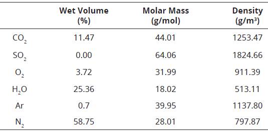
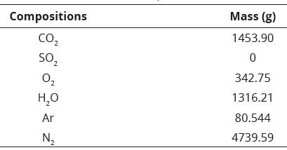
The humidity of the bagasse H = (mv/ma) can be found using the molar volume of the flue gas at operating temperature (155 °C), where mv = mass of moisture present, ma = total dry mass. Trial and error methods were conducted to determine the expected drying parameters at the low drying time. For an arbitrary volume of 10 m3 bagasse, the calculation is made to obtain the mass of flue gases (Table 7) and drying parameters (Table 8). The drying time is within the expected range for a flash drying system.
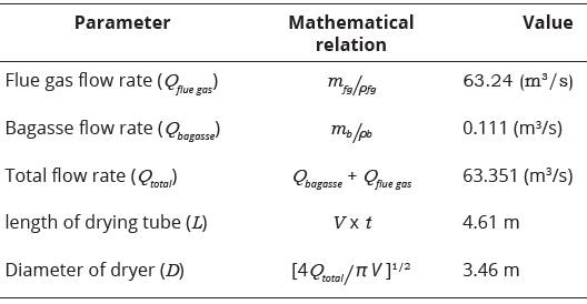
According to the company, the estimated flue gas exiting from the boiler is m fg = 227,672 kg/hr assuming pfg = 1 kg/m3 of gas flow. The bagasse flow rate is m b = 60 tph assuming pb = 150 kg/m3 of bagasse flow. Calculating a total flow balance with the summation of the flue gas and bagasse flow, we can determine the desired diameter and length of the dryer (Table 9).
Parametric Study for Dryer
Due to the size restriction of a 6 x 6 x 25 m footprint for the bagasse drying system, the drying tube was optimized for both performance and design requirements emplaced by the company. The fluid mixture velocity influences the dryer length (Fig. 1(a)). As the dryer length should be kept to a minimum, it is advantageous to keep the fluid mixture velocity to a minimum; thus, the values calculated for the arbitrary volume of the bagasse (V = 6.742 m/s, and L =4.61 m) were kept fixed and used.
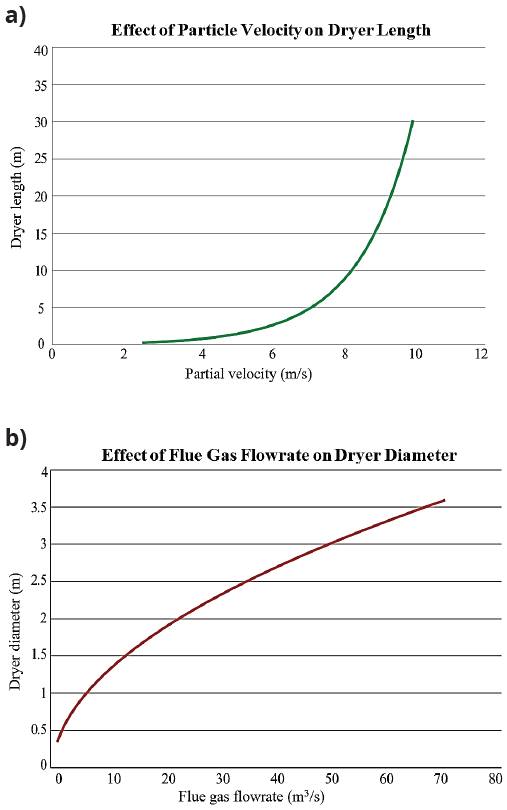
Fig. 1 (a) Effect of particle velocity on dryer length, (b) Effect of flue gas flowrate on dryer diameter
At fixed dryer length (L = 4.61 m), it is necessary to reduce the dryer diameter (D) to limit the flow rate of flue gas into the dryer. The excess flue gas is directed to the exhaust stack as per the current operation. However, the optimum flow rate of the flue gas can be estimated at a particular dryer diameter using the figures presented in Fig. 1(b).
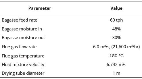
From this analysis, it has been determined that a flow rate of flue gas of 6 m3/s, results in a dryer diameter of 1 m (Fig. 1(b)). This dimension allows for a minimal footprint while being comparable to the required inlet for the cyclone, thus reducing losses, and reducing the chance of bagasse becoming stuck and igniting during operation (Table 10).
Heat Transfer Analysis of Drying Tube
Mass balance
Assuming the desired outlet bagasse moisture at 30% (as per the expected goal), an overall mass balance can be achieved as below-
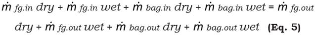
As the dry components of bagasse and flue gas are equal before and after the reaction, ignoring these parameters the modified mass balance equation is-

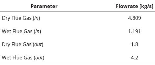
This mass balance can be broken into its respective mass flowrates and moisture content as shown below-

Calculated summary from the from the above equations, presented in Table 11 and Table 12.
Bagasse Exit Temperature
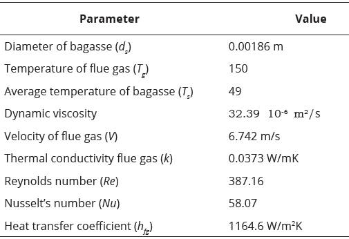
To calculate the temperature of bagasse particles at the exit of the drying tube, a lumped capacitance method is assumed with flue gas temperature of 150 °C, bagasse properties are constant, bagasse particles are spherical and have no effect on neighboring particles. Using a free body diagram of the idealized case (Fig. 2) and using flue gas and bagasse properties (Table 13), the final bagasse temperature (Tf) can be determined using the following relation-
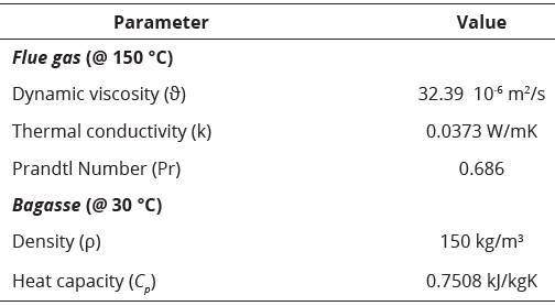
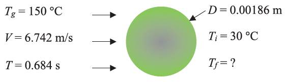
Using the empirical correlations for heat transfer coefficient available for gas-particle flows [6], we can determine the Reynolds number (Re = 387.16) and Nusselt number (Nu = 58.07) to obtain the value h fg = 1164.52 W/m2K as well as T f = 67.96 °C. g
Heat Loss through Drying Tube
In order to determine the insulation, thickness the Fig. 3 and Fig. 4 was used and result summarized in Table 14.
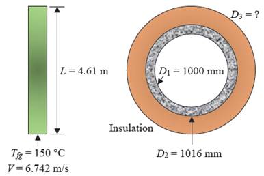
Fig. 3 Free body diagram of a drying tube. (Left) Side view, (right) internal view exaggerating layers.
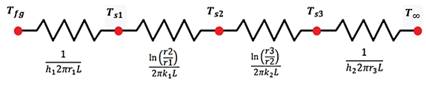
Table 14 summarizes the additional parameters used, and the correlations or equations used to find them. The heat transfer throughout the drying tube occurs via three mechanisms, (i) Convective (internal flow), (ii) Conductive (through drying tube, and insulation) and (iii) Convective (external flow) (Table 15).

An analysis is first conducted to find the outer surface temperature of the drying tube without insulation. The overall heat transfer rate is calculated by Eq. 9-10.
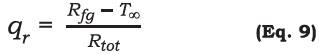
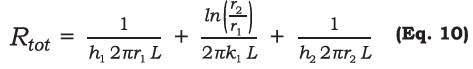
By establishing the overall heat transfer rate, we can conduct a simple nodal analysis, working from inside the drying tube to the outside.
This analysis allows the determination of the inner (96.06 °C) and outer (95.96 °C) surface temperatures.
Knowing the outer temperature of the drying tube, we can now specify an appropriate insulative material. A500 Insulative paint (Product catalogue, Insulpaint Australia Pty Ltd, 2004) from Insulpaint Australia was chosen to be applied to the outside of the drying tube. A parametric study to find an appropriate thickness of insulation was conducted (Fig. 5). Including insulation, R tot becomes,
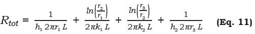
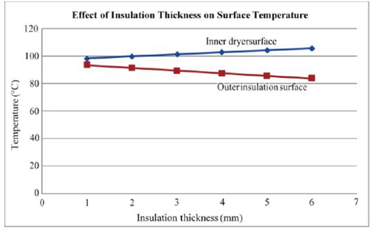
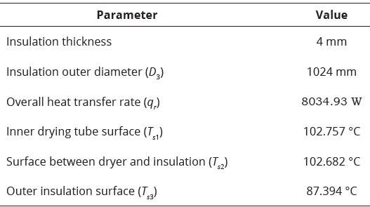
It is recommended that a paint coating of between 2-5 mm be applied. Assuming a coating of 4 mm, Table 16 summarizes the calculated surface temperatures for completeness.
Flue Gas Exit Temperature
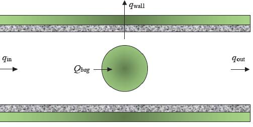
To calculate the exit temperature of the flue gas, the overall energy balance has been considered as shown in Fig. 6. It should be noted that the “one bagasse particle” is a total representation of all the individual particles in the dryer. The overall balance is described below-
From Table 16 the overall heat transfer rate out of the dryer wall is 8034.93 W with a 4 mm insulative paint applied. Therefore the Eq. 12 can be solved for all other parameters.

Heat Transfer into Bagasse
In works published by Mujumdar (Mujumdar, 2014), the heat transfer rate (per volume) between and gas and solid phase can be calculated via the following Eq. 13.
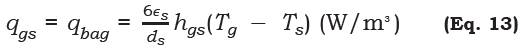
where, Є s = solid volume fraction in the mixture, d s = diameter of bagasse particle (m), h gs = heat transfer coefficient (W/m2K), T g = temperature of the gas, and Ts = average temperature of the bagasse. The solid volume fraction is calculated as Є s = Q b /(Q b +Q g ) = 0.111/ (0.111+6.0) = 0.01816. Using the Baeyens et al. (Maurice, Mezhericher, Levy, & Borde, 2015) correlation for the Nusselt’s number, the heat transfer coefficient can be established and the heat transfer rate calculated (Table 17).
Thus, by substituting the known values into Eq. 13, we can solve the heat transfer rate (per volume) into a singular bagasse particle as q gs = q bag = 6,892,047.57 W/m3. Knowing the volume of one particle the heat transfer rate into one particle is q bag = 0.02322 W, the total heat transfer rate can be found as q bag, tot = 765541 W.
Heat Transfer Rate In and Out
To calculate the energy at the inlet and outlet of the drying tube, an analysis of the flue gas enthalpy was conducted, assuming constant pressure throughout. Expressions for the enthalpy at the inlet and outlet are presented below (Eq. 14-15). Table 18 summarizes the parameters used to solve the enthalpy analysis.
Table 18 Summary of parameters involved in the enthalpy energy balance (Note: Constant thermal properties are assumed throughout)
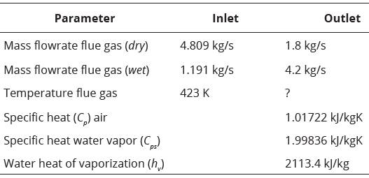


Thus, Eq. 14 and Eq. 15 gives qin = 5593055 W and qout = 8876280 + 10224.108 T fg out respectively. By subbing all components into Eq. 15, we can solve the outlet temperature T fg out = 396.8 K = 123.8 °C. Table 19 below summarizes the parameters determined via the heat and mass analysis as described above.
Cyclone separator
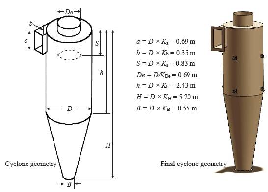
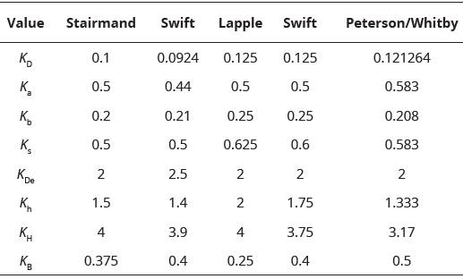
In the case of separating the dried bagasse from the moisture-rich flue gas exiting the dryer the most common form of the dry scrubber is a cyclone separator (Strumiłło, L. Jones, & Zyłła, 2014)(Moor, 2007)(Bashir, 2015)(Pynadathu, Thomas, & Arjun, 2014). The most common type of dryer is shown in Fig. 7. Over the last 50 years, the design and optimization of cyclones have been extensively investigated by researchers such as Stairmand, Swift 1, Lapple, Swift 2 and Peterson/ Whitby (Leith, 1990). Each design determines the various component lengths and diameters as a function of the body diameter (D ) as outlined below in ref (Leith, 1990).

From this review of the literature and consultation with the company (required throughput rate of 60 tph), a high throughput cyclone is required. The scheme chosen is the Swift scheme (Leith, 1990) which is a function of the input flow rate, inlet velocity and combined density (Table 20).
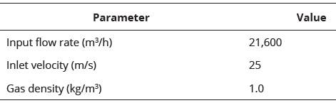
The main diameter is calculated and found to be D = 1.39 m ( ) according to the ref. (Leith, 1990). In reference to Fig. 8, the following equations describe the functional relationships between the major diameter and the other functional variables (Bashir, 2015)(Leith, 1990).
The pressure drops = 13.38 cm of water ( 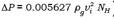 ) across the cyclone is a function of the velocity heads at the inlet and outlet N
H
= 3.804 (Nh = (KVH)(ab)/De2), the density of the gas ( kg/m3), and the velocity of the inlet (V
i
m/s). Using the Shepard and Lapple empirical relationship for velocity heads at the inlet and outlet of the cyclone, the empirical constant has a value K
VH
= 16 for tangential inlets and K
VH
= 7.5 for cyclones with an inlet vane [10].
) across the cyclone is a function of the velocity heads at the inlet and outlet N
H
= 3.804 (Nh = (KVH)(ab)/De2), the density of the gas ( kg/m3), and the velocity of the inlet (V
i
m/s). Using the Shepard and Lapple empirical relationship for velocity heads at the inlet and outlet of the cyclone, the empirical constant has a value K
VH
= 16 for tangential inlets and K
VH
= 7.5 for cyclones with an inlet vane [10].
Specification of Fan
A forced draught fan is installed upstream of the drying tube to ensure the desired flue gas flowrate is achieved. To ensure the correct specification of the fan, the losses in the system must be considered. This can be achieved by applying a control volume (Fig. 9) and solving Bernoulli’s equation (Eq. 16).
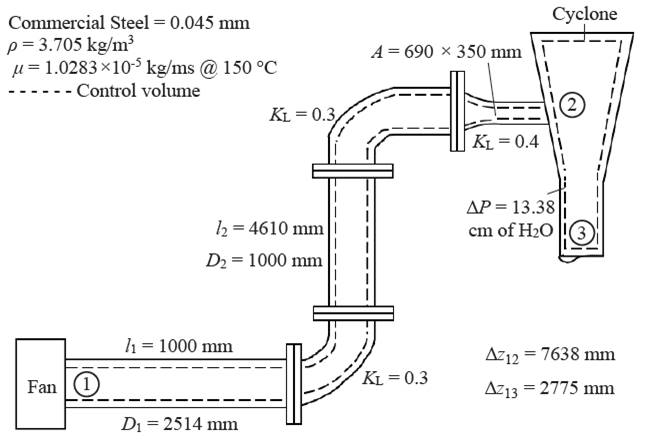
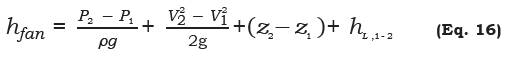
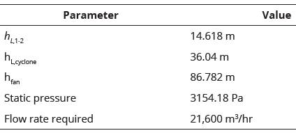
where, P - absolute pressure (Pa), V - velocity (m/s), z - elevation (m), h L ,1-2 - head loss (m). The h L ,1-2 can also be described as h L , 1-2 = h dryer + h cyclone . Table 22 below contains the parameters, equations, and assumptions made to solve for the required fan head.
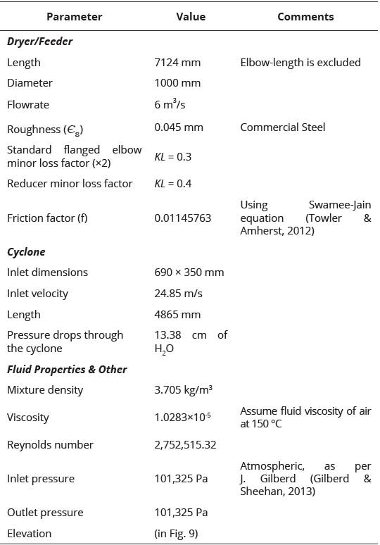
The head loss through the dryer can be calculated via Eq. 17
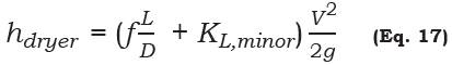
while the head loss due to the pressure drop in the cyclone can be found via hdryer = ΔP/pg. With the given information, Eq. 16 can be solved (Table 23).
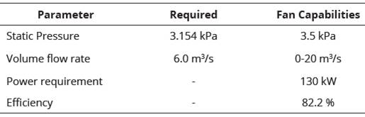
To be able to source parts and spares nationally a fan will be selected from Aerotech (Company catalogue, Aerotech Fans Pty. Ltd.). It has been determined that a centrifugal pump is most suited for the bagasse drying system. From these options, it is apparent that the MAVX405 (Table 24) (Company catalogue, Aerotech Fans Pty. Ltd.) is the only option that satisfies our criteria. It has the required flow rate, while also having a large enough static pressure head for our requirements.
Drying Tube Selection
After consultation with the company about the importance of design aspects and design requirements, a weighted decision matrix (Ouye, Facility Technics Facility Management Consulting) was devised (Table 25) and determined that the single-pass circular drying tube is the most appropriate and accepted by company engineers.
Proposed Structure
After determining all dryer design parameters and parts specifications, this paper proposes an improved design for the bagasse drying system for the boiler of the cogeneration plant (Fig. 10). A scale model of the overall structure of the proposed design has drawn (Fig. 10), which included all the parts (feeders, fan, drying tube, and cyclone). All parts of the proposed design (Fig. 10) are supported by a structure that fits within the specified area of the mill without hindering any accessibility problem. The proposed design can be constructed in-place to dry the bagasse. Since all the parts and specifications for this design are derived for industrial scale, it will be easy to modify the proposed design with necessary bagasse and boiler information for any kind of industrial bagasse drying system.

Conclusión
This work has analyzed the step by step boiler and bagasse information for a case-study based problem to determine all dryer design parameters and parts specifications for an industrial scale bagasse drying system. The proposed design will be capable of drying bagasse and reducing moisture content from 48% to 30% for the boiler of the cogeneration plant. The selected feeder for the proposed design is 36 x 36 inch, 20 RPM, Meyer rotary feeder for a drying tube of length 4.61 m having 3.46 m diameter. However, with a trial-based optimization for 60 tph of bagasse flow and 150 °C of flue gas temperature, the diameter can be reduced to 1 m for certain estimated dying. In the proposed design the drying tube will have insulation of 4 mm thickness and will be painted with a heat protected coating. The separation of the flue gas and bagasse will occur in a flash cyclone separator. The design is planned to be operated by a centrifugal forced draught pump and the selected drying tubes are single-pass circular type. On the basis of this design analysis and specifications, an efficient industrial scale bagasse drying system can be placed in any sugar mill cogeneration plant to achieve a moisture reduction. However, this work reserves the following points for future research: Structural design analysis of all components, Estimated cost for the overall setup, Installation and run.

