


Servicios Personalizados
Revista
Articulo
 Inglés (pdf)
 Articulo en XML
 Referencias del artículo
 Enviar articulo por email
Indicadores
-
 Citado por SciELO
 -
 Accesos
Links relacionados
-
 Citado por Google
 -
 Similares en
SciELO
Similares en
SciELO -
 Similares en Google
Compartir

 Permalink
Ingeniería e Investigación
versión impresa ISSN 0120-5609
Ing. Investig. v.27 n.1 Bogotá ene./abr. 2007
Hugo Ernesto Camero Sanabria1
1 Ingeniero civil. Especialista en Finanzas de la Universidad de Los Andes, Colombia. Premio al "Merito Académico en Construcción", Asociación de Ingenieros Civiles, Universidad Nacional de Colombia (AICUN). Gerente, firmas de diseño y construcción de edificaciones. Actual Gerente, Construdiseños Alta Ingeniería Ltda. construdisenosai@hotmail.com, construdisenos@netcard.net.co
ABSTRACT
This article presents a methodology for designing slabs on grade for industrial floors where there is an eccentricity between the slab centroid and the gravity centre loads of the loaded axle of forklift trucks travelling over the floor. An example was used for analysing how Portland Cement Association (PCA) and the Wire Reinforcement Institute (WRI) methods are inadequate for designing floors subjected to this condition. The new proposal for designing slabs on grade for industrial floors has been called the Camero method. An example of an industrial floor designed to be capable of sustaining an infinite number of load applications (or 50-year life) was compared to the results of the Camero method and PCA and WRI’s simplified methods. Industrial floors should be capable of sustaining an infinite number of load applications (50-year life) if designed with the Camero method; on the other hand, if designed using PCA and WRI methods they will only last one year (in this example the number of axle load applications in a 1-year period was equal to the number of allowable repetitions) because they will not be able to sustain an infinite number of load applications. It was concluded that designing plain concrete slabs (without reinforcement) on grade according to PCA and the WRI methods leads to slab fatigue, even though extreme fibre stress should not exceed 50 percent (50%) of static modulus of concrete rupture and slabs should sustain an infinite number of load repetitions (infinite amount of forklift truck traffic) were considered parameters in their design.
Keywords: floor slab on grade, Portland Cement Association, Wire Reinforcement Institute, slab design on grade, floor design, industrial floor slab, concrete floor, concrete slab on grade, pavement, rigid pavement.
RESUMEN
Se presenta una metodología para el diseño de losas sobre terreno para pisos industriales en donde hay excentricidad entre el centroide de la losa y el centro de gravedad de las cargas del eje cargado del montacargas que transita sobre el piso. Mediante un ejemplo se analiza cómo los métodos de diseño de pisos de la Portland Cement Association (PCA) y la Wire Reinforcement Institute (WRI) son inadecuados para el diseño de pisos sometidos a esta condición. El nuevo método propuesto para diseñar pisos industriales ha sido llamado Camero. Mediante un ejemplo, un piso industrial es diseñado para ser capaz de admitir un número infinito de aplicaciones de carga (o un periodo de vida útil del piso de 50 años), comparando los resultados del método Camero y los simplificados de la PCA y la WRI. El piso industrial será capaz de admitir un número infinito de aplicaciones de carga (50 años) si es diseñado con el método Camero. De otra manera: si es diseñado por los métodos de la PCA y la WRI únicamente durará un año (En este ejemplo, en el periodo de un año el número de aplicaciones del eje cargado es igual al número de repeticiones admisibles), por eso el piso industrial no será capaz de admitir un número infinito de aplicaciones de carga. Concluimos que el diseño de losas sobre terreno de concreto simple (sin refuerzo), de acuerdo con la metodología de la PCA y la WRI, conduce a losas diseñadas a fatiga, a pesar de haber considerado en el diseño que el esfuerzo en las fibras superiores no excedería el 50% del módulo de rotura del concreto y que admitirían un número infinito de repeticiones de carga (número infinito de tránsito del montacargas de diseño).
Palabras clave: placas de piso sobre terreno, Portland Cement Association, Wire Reinforcement Institute, diseño de losas sobre terreno, diseño de pisos, placas de pisos industriales, losas de pisos industriales, pisos de concreto, pisos de concreto sobre terreno, pavimentos, pavimentos rígidos, soleras, soleras de hormigón, soleras industriales.
Recibido: agosto 15 de 2006
Aceptado: marzo 1 de 2007
Introduction
Designing slab floors on grade for industry consists of designing slabs for storage and traffic loads produced by vehicles and forklift trucks, these generally being the most critical. This article shows how the Portland Cement Association (PCA) and Wire Reinforcement Institute (WRI) simplified methods for designing slabs for forklift truck traffic consider the bending moments applied to slabs smaller than those presented under operational conditions by forklift trucks being misaligned with the slab’s longitudinal axis centre (eccentricity between slab centroid and the centre of the forklift truck’s loaded axle).
The article develops a set of equations for analytically calculating the bending moment applied to the slab by forklift truck loads. A new method for designing industrial floors is suggested (herein referred to as the Camero method).
An example is for comparing the behaviour of an industrial floor designed by the Camero method with one designed by PCA and the WRI methods.
Introducción
El diseño de las losas sobre terreno (placas de contrapiso) para pisos industriales comprende generalmente el de las losas para cargas de estantería de almacenamiento y cargas de tráfico producidas por vehículos y montacargas, siendo estas últimas generalmente las más críticas. Se demostrará en el articulo cómo los métodos simplificados de diseños de losas para tránsito de montacargas de la Portland Cement Association (PCA) y la Wire Reinforcement Institute (WRI) consideran momentos flectores actuantes sobre las losas mucho menores respecto de los que se presentan en condiciones de operación con montacargas desalineados con el eje longitudinal central de la losa (excentricidad entre el centroide de la losa y el centro de cargas del eje cargado del montacargas).
Desarrollaremos todas las fórmulas para calcular analíticamente el momento flector actuante sobre la losa debido a las cargas del montacargas que transita sobre ella. Una vez hecho esto, propondremos un nuevo método para diseñar pisos industriales, al que hemos llamado Camero.
Posteriormente, con un ejemplo compararemos el comportamiento de un piso diseñado por el método Camero y por los de la PCA y la WRI.
Stress due to load
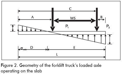
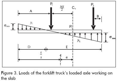
When a forklift truck’s longitudinal axis centre does not coincide with a slab’s longitudinal axis centre, eccentricity takes place between the slab’s floor centroid (pavement) and the forklift truck’s loaded axle centre. Figure 1 shows the geometry of the forklift truck’s loaded axle. Figures 2 and 3 show the loaded axle working on the slab. The forklift truck’s longitudinal axis has been called centre Cc and the slab’s longitudinal axis centre ¢.
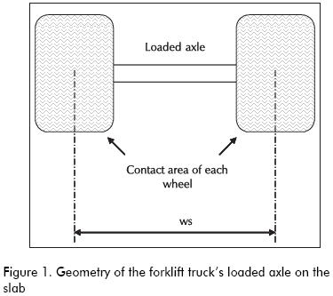
WS: Wheel spacing of the forklift truck’s loaded axle
A: Distance between the slab’s left edge and the centreline of the first wheel of the forklift truck’s loaded axle
B: Distance between the slab’s right edge and the centreline of the second wheel of the forklift truck’s loaded axle
C: Distance between the slab’s left edge and the centreline of the second wheel of the forklift truck’s loaded axle
D: Distance from the slab’s left edge to the point where subgrade reaction is zero
E: Distance from the slab’s right edge to the point where subgrade reaction is zero
L: Slab width
P1: Forklift truck’s load applied to the loaded axle’s left wheel
P2: Forklift truck’s load applied to the loaded axle’s right wheel
e: Eccentricity corresponds to the distance between the centroid of the slab (longitudinal axis centre of the slab, called ¢) and the loads centre of gravity of the forklift truck’s loaded axle (Cc)
σmax: Maximum stress developed on the slab by forklift truck interaction (vehicle axle load) – slab (pavement) – subgrade
σmin: Minimum stress developed on the slab by forklift truck interaction (vehicle axle load) – slab (pavement) – subgrade
The maximum stress developed by the forklift truck – slab (pavement) – subgrade interaction is calculated (when P1 = P2, analysing a 1 meter-wide slab strip or 1 foot-wide slab strip):
Where:
 = Stress on the soil (subgrade) due to forklift truck load
L = Slab width
e = Eccentricity corresponds to the distance between the centroid of the slab (longitudinal axis centre of the slab, called ¢) and the loads’ centre of gravity of the forklift truck’s loaded axle (Cc). Figure 3 shows Cc when P1 = P2.
It has been demonstrated in texts on the mechanics of materials that, for beams, the relationship between bending moment and radius of curvature is as follows:
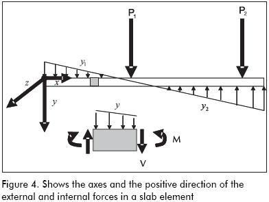
These equations relate to the bending moment M in a given transversal section of an elastic beam whose moment of inertia regarding the neuter axis is I, with curvature d2y/dx2 of the elastic material. The direction of the axes is illustrated in Figure 4. In equations (2) and (3), M = Mzz and I = Izz. E corresponds to the material’s modulus of elasticity; in the case of concrete, we call it Ec.
How to calculate the bending moment applied on the slab
Equation (3) is generally applied to pavements and industrial concrete floor designs. It has its origin in deflection analysis of a slab acting as a beam with the following hypotheses (Camero, 2002):
- The flat sections of a slab (beam) remain flat after being subjected to flexion (bending); and
- Stresses are proportional to strain.
To calculate the applied bending moment, the structural analysis of the industrial floor slab in Figure 3 must be considered. In this case, the equation for the soil reaction curve is calculated as follows (see axes’ symbols in Figure 4: ↓+ denotes vertical positive force):
The equilibrium differential equations must be born in mind when calculating the bending moment:
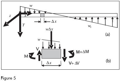
For Figure 5 and with equation 3, we have:
The bending moment between point 0 and L (see Figures 2, 3 and 4) is then calculated by adding the bending moments caused by each load for equilibrium.
From Figure 3 and equation 4, we have:

This results from load y1.
Then from equation 6 and for the conditions of Figures 2, 3 and 4, we have:
The following is obtained by developing the previous equation:
Equation (8):
valid for x between 0 y D 0≤x≤D
Equation (9):
valid for x > D
My1 indicates the bending moment caused by load y1. Calculating the bending moment for the rest of the loads using the same methodology and using the same notation, we have:
Equation (10):
where ⟨ x - D ⟩ is the singularity function that indicates: valid only for x > D
Equation (11):
valid for x > A
Equation (12):
valid for x > C
The total bending moment for each point of the slab, at a distance x from the edge, is thus (see Figures 2, 3 and 4):
Equation (13):
Where My1 is defined by equations 8 and 9 and My2, Mp1, Mp2 by equations 10, 11 and 12, respectively.
This gives the bending moment calculated on the slab by any type of vehicle (forklift truck or truck). Equation (13) is also applicable to pavements for any type of vehicle.
Proposed design methodology (Camero method)
Calculate the bending moment applied to the pavement, in accordance with equation 13.
If designing a plain concrete slab (without reinforcement), continue as follows:
Calculate the maximum bending stress applied to the slab (pavement). The following flexural equation should be born in mind:
Where:
σ max bending = maximum bending stress applied to the industrial floor (slab) or pavement in direction x
M = bending moment calculated in equation 13
c = distance from the slab farthest away from the fibre to the centroid axis of the transversal section of the slab or pavement
I = moment of inertia of the slab’s transversal sectional regarding centroid axis and variable “c” measured starting from this axis
Establish allowable stresses. The stresses should not exceed the elastic limit at any point.
The following maximum compression and tension stress are recommended:
Equation (14):
σ max compression = 0.45f´c = allowable concrete compression stress
 is allowable concrete tensile stress Passive steel was used as control for shrinkage and concrete temperature effects
 If passive steel is not placed and inelastic concrete deformation is allowed, then the same modulus of rupture of concrete will apply (MR).
Where f´c is concrete compressive stress in Kg/cm2 (1 ksi=6.89 MPa=70.37 Kg/cm2)
Calculate the thickness of the slab or pavement. The usual way to do this calculation is to use a 1.0 meter-wide slab strip (or 1.0 foot-wide slab strip), resulting in:
Equation (15):
Where:
σ = is the allowable bending stress, calculated with equation (14)
M = is the bending moment calculated with equation 13
b = is the width of the transversal section of slab or pavement being analysed, taken as 1 meter or 1 foot (12 inches)
T = is slab or pavement thickness
Verify that the applied stress calculated in equation 15 is smaller than that allowable, equation 14. If it is not satisfactory, increase the slab thickness.
Verify that the reaction on the subgrade is smaller than the bearing capacity of the same. Confirm this with equation 1. Do not forget to consider slab weight, which has not been included in equation 1 because, when the slab is continually supported on the ground, slab weight does not produce bending.
Calculate the distance between joints according to concrete shrinkage, temperature and creep. Verify slab shear stress resistance due to load action.
If an ultimate strength design is required, see Camero, 2002.
Example for calculating bending moment
Example 1: Calculating the bending moment for designing an industrial floor with the following values:
Characteristics of the materials, site:
Concrete compressive strength: f´c=28 MPa (4,000 psi)
Concrete modulus of elasticity: Ec=21,000 MPa (3,000 ksi)
Modulus of rupture: MR=4.2 MPa (600 psi).
Subgrade modulus: k=2.8 Kg/cm3 (100 pci)
Safety factor: 2.0
Slab width: 3.66 mts=12 feet.
Forklift truck specifications:
Total axle load: 13,000 Kg (28.6 kips=127.4 KN), evenly distributed as in Figure 3, P1=P2=6,500 Kg (14.3 Kips=63.7 KN).
Wheel spacing (WS): 1.83 m (72 inches).
Tire pressure: 5.6 Kg/cm2 (80 psi).
Slab width where the forklift truck goes was determined by (Figures 2 and 3):
A=1.73 m (68.11 inches)
B=0.10 m (3.94 inches).
C=3.56 m (140.16 inches)
L=3.66 m (144.09 inches)
The following moments were found by calculating the bending moment applied according to PCA and WRI methodologies (their design charts are given in Ringo and Anderson, 1996):
M PCA method=2,900 pounds - inch /inch=1.32 ton – Mts/Mts=12.9 KN – m/m
M WRI method=2,850 pounds – inch / inch=1.3 ton – Mts/Mts=12.7 KN – m/m
The following is obtained if the applied bending moment is calculated according to equation 13:
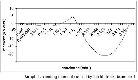
M Camero method=4,850 pounds – inch / inch=2.2 ton – Mts/Mts=21.6 KN – m/m
It was found for this example that the real bending moment applied to the slab was 70% greater than that calculated by the PCA and/or WRI methods.
Graph 1 illustrates the bending moment applied on the slab calculated with equation 13 (Camero method):
A plain concrete slab was obtained (without reinforcement) having t=19.3 cm thickness (7.6 inches) with a safety factor of 2.0 and according to PCA and the WRI design charts (the same was obtained when applying equation 15).
A plain concrete slab having t=24.9 cm (9.8 inches) thickness was obtained with bending moment obtained according to the Camero method.
The preceding results would be identical if highway pavement were to be designed instead of an industrial floor. The question was thus posed: Why does the pavement work with PCA and WRI design thickness methods?
If the maximum stresses applied to the slab were calculated with PCA and WRI methods the following was found (applying equation 15) with t=7.6 inches (19.3 cm) and M=2,900 pounds – inch/inch (12.9 KN – m/m):
σmaximum applied tensile stress = 300 psi=2.1 MPa=21 Kg/cm2
σmaximum applied compressive stress= 300 psi=2.1 MPa=21 Kg/cm2
Then when applying the maximum stress criteria (equation 14), it can be observed that the slab suffers inelastic strain due to its tension stress and this process can now be witnessed.
If the stresses applied to the slab (pavement) are calculated according to the applied bending moment found with the CAMERO method (equation 13), it can be found that with t = 7.6 inches (19.3 cms.) and M = 4,850 pounds – inch/inch (21.6 KN – m/m):
σmaximun applied tensile stress = 500 psi = 3.5 MPa = 25 Kg/cm2
σmaximun applied compressive stress = 500 psi = 3.5 MPa = 35 Kg/cm2
The above calculation led to concluding that if the slab (pavement) had no passive steel it would present inelastic deformation due to its tensile stress.
If the σapplied/MR relationship is calculated then the following is found:

If the concrete is subjected to repeated flexure, then repeating the same load produces material fatigue and thereby slab (pavement) failure. MA Minor has investigated the subject and found that if a load produces bending stresses greater than half concrete rupture modulus, then such load induces material fatigue. Minor’s charts are published in Yoder and Witczak, 1975 and they have been adopted by the Portland Cement Association method.
Plain concrete slabs will generally sustain an infinite number of load repetitions (infinite amount of forklift truck traffic), as long as extreme fibre stress does not exceed 50% of static rupture modulus.
Minor’s charts show that there are 50 allowable repetitions of loaded axles for the 0.83 (σapplied/MR=0.83) relationship with 127.4 KN (13,000 Kgs.=28.6 Kips) for the given example. Current PCA and WRI safety factor for example 1 is 1.2 and not 2.0 as we believed according to PCA and WRI design charts. The previous safety factor allowing only 50 repetitions of loaded axles explains why the slab (pavement) works well at the beginning but begins to fail from fatigue within a short period of time.
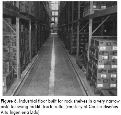
A typical example of an industrial floor in which the forklift trucks’ loaded axle centroid is eccentric with the slab centroid (and will always remain so during forklift truck operation) is illustrated in Figure 6. It shows storage racks with a narrow aisle where the aisle width is similar to forklift truck width plus a small margin. Forklift trucks are used which turn 90°, also known as “swing forklift trucks.”
Conclusions
A new method for designing slabs on grade for industrial floors is presented (the Camero method) and its advantage was that it analytically calculated the bending moment applied by forklift trucks to the slab. The Camero method showed that forklift trucks’ bending moment applied to the slab was bigger than those considered by the simplified design methods (i.e. PCA and WRI methods). This article explains how industrial floors designed by traditional methods reduce useful floor life.
Industrial floor design using the Camero method can sustain an infinite amount of traffic whilst floors designed by traditional methods will only sustain a limited amount of traffic (limited number of load repetitions); in other words, for a useful life of 50 years, a floor designed by the Camero method will last 50 years. The same floor designed with traditional methods can only last one year because it will support a smaller amount of traffic (in this example, in 1 year period, the number of axle load applications on the concrete is equal to the number of allowable repetitions).
The PCA and WRI slab on grade design methods for industrial floors led to a design for concrete fatigue, even though 2.0 was used when estimating the safety factor (calculated in relation to the modulus of rupture) that allows that the slabs of plain concrete sustain an infinite number of load repetitions. This happens in the case that the forklift truck’s centroid loaded axle is eccentric with the slabs’ centroid. When the preceding occurs, the bending moment applied by the forklift truck loads is greater than that proposed by the PCA and WRI methods; the slabs so designed will allow a smaller amount of load repetitions to fail by fatigue.
Designing slabs on grade for industrial floors should use the recommended process (Camero method), having a safety factor of 2.0. If the slabs’ useful life (pavement) is very short, the safety factor can be decreased but the traffic the slab will have during its period of useful life must be calculated to verify that there will be no failure due to fatigue.
Conclusiones
Se presenta un nuevo método para el diseño de losas sobre terreno para pisos industriales. Este nuevo procedimiento de diseño es llamado el método Camero. Su ventaja es que analíticamente calcula el momento flector transmitido por el montacargas a la losa. El método Camero revela que el momento flector transmitido por el montacargas a la losa es mucho más grande que aquel que ha sido considerado por los métodos tradicionales de diseño, entre ellos los de la PCA y WRI. Este artículo detalla además cómo los pisos industriales diseñados con los métodos tradicionales reducen su periodo de vida útil.
Los pisos industriales diseñados con el método Camero pueden admitir un número infinito de trafico, en cambio los diseñados con los métodos tradicionales únicamente admitirán un número finito de tráfico (número limitado de repeticiones de carga). Es decir, para un periodo de vida útil de 50 años, un piso diseñado con el método Camero durará 50 años. El mismo piso diseñado con los métodos tradicionales puede durar únicamente un año, ya que soportará un número de tráfico menor. (En este ejemplo, en el periodo de un año el número de aplicaciones del eje cargado es igual al número de repeticiones admisibles por el concreto).
El método de diseño de losas sobre terreno para pisos industriales de la PCA y la WRI nos conduce a un diseño por fatiga del concreto a pesar de haber utilizado en el cálculo un factor de seguridad de 2,0 (medido con relación al módulo de rotura, MR) que permite que las losas de concreto simple admitan un número finito de repeticiones de cargas. Lo anterior en el caso de que el centroide del eje cargado del montacargas sea excéntrico con el centroide de la losa. Cuando lo anterior ocurre el momento flector ocasionado por las cargas del montacargas es mucho mayor al que tienen en cuenta los métodos de diseño de la PCA y la WRI, y las losas así diseñadas admitirán un número pequeño de repeticiones de cargas a fallar por fatiga.
Proponemos que para diseñar losas sobre terreno para pisos industriales se utilice el método Camero que hemos propuesto, con un factor de seguridad de 2,0. Si el periodo de vida útil de la obra es muy corto se puede reducir el factor de seguridad pero se deberá calcular el tránsito que tendrá la losa durante el periodo de vida útil para verificar que no habrá falla por fatiga.
Notation
The following symbols are used in this paper:
WS: Wheel spacing of the forklift truck’s loaded axle
A: Distance between the slab’s left edge and the centerline of the first wheel of the forklift truck’s loaded axle
B: Distance between the slab’s right edge and the centerline of the second wheel of the forklift truck’s loaded axle
C: Distance between the slab’s left edge and the centerline of the second wheel of the forklift truck’s loaded axle
D: Distance from the slab’s left edge to the point where subgrade reaction is zero
E: Distance from the slab’s right edge to the point where subgrade reaction is zero
L: Slab width
P1: Load applied by the forklift truck on the loaded axle’s left wheel
P2: Load applied by the forklift truck on the loaded axle’s right wheel
e: Eccentricity. It corresponds to the distance between the slab’s centroid (longitudinal axis center of slab, called ¢) and the loads’ gravity center of the forklift truck’s loaded axle (Cc).
¢: The slab’s central longitudinal axis. The slab’s centerline
Cc: Load gravity center of forklift truck’s loaded axle
σmax: Maximum stress developed in the slab by the forklift truck (vehicle axle load) – slab (pavement) – subgrade interaction
σmin: Minimum stress developed in the slab by the forklift truck (vehicle axle load) – slab (pavement) – subgrade interaction
σ max bending: Maximum bending stress applied to the industrial floor (slab) in direction x
M: Bending moment.
c: Distance from the fiber farthest away from the slab to the central axis of the slab’s transverse section
I: Moment of inertia of the slab’s transverse sectional, regarding central axis and variable “c” measured from this axis
y1: Distributed load on the slab by forklift truck (vehicle axle load) – slab (pavement) – subgrade interaction and with downward direction (positive vertical force: ↓+)
y2: Distributed load on the slab by the forklift truck (vehicle axle load) – slab (pavement) – subgrade interaction and with upward direction
M y1: Indicates the bending moment caused by load y1
M y2: Indicates the bending moment caused by load y2
M p1: Indicates the bending moment caused by load P1
M p2: Indicates the bending moment caused by load P2
f´c: Compressive strength of plain concrete as measured from standard cylinder [6 inch x 12 inch (152 mm x 305 mm)] test
Ec: Modulus of concrete elasticity
MR: Modulus of concrete rupture
k: Modulus of subgrade reaction
Bibliographic
Yoder, E.J. and Witczak, M.W., Principles of Pavement Design., 2nd. edition, John Wiley & Sons, Inc., New York, 1975. [ Links ]
Ringo, B.C. and Anderson R.B., Designing Floor Slabs On Grade., 2nd. edition, Illinois, The Aberdeen Group, 1996. [ Links ]
Camero, H.E., Diseño y Construcción de placas de contrapiso industriales sin juntas en concreto reforzado., Asociación de Ingenieros Civiles de la Universidad Nacional de Colombia’s Journal, No. 31, Junio, 2002, pp. 12-13. [ Links ]

