


Servicios Personalizados
Revista
Articulo
 texto en
  Español (pdf)
 Articulo en XML
 Referencias del artículo
 Enviar articulo por email
Indicadores
-
 Citado por SciELO
 -
 Accesos
Links relacionados
-
 Citado por Google
 -
 Similares en
SciELO
Similares en
SciELO -
 Similares en Google
Compartir

 Permalink
Ingeniería e Investigación
versión impresa ISSN 0120-5609
Ing. Investig. v.30 n.2 Bogotá mayo/ago. 2010
Edgar Mauricio Vargas Solano1 and Fredy Alexander Garzón Rodriguez2
1 Chemical Engineering. M.Sc. Chemical Engineering, Universidad Industrial de Santander (UIS), Santander, Colombia. Associate Professor, Faculty of Natural Sciences and Engineering, Universidad Jorge Tadeo Lozano, Bogotá, Colombia. edgar.vargas@utadeo.edu.co 2 Food Engineering, Universidad Jorge Tadeo Lozano, Bogotá, Colombia. fredygarzonrodriguez@yahoo.com
ABSTRACT
Designing specific equipment as a teaching and investigation tool in engineering is an interesting alternative for reducing costs and contributing towards local appropriation of knowledge and technology. It makes adaptation to the environment easier and reduces technology dependency. This work shows how a semiautomatic hot-air tray-dryer was designed, built and brought into operation, describing the pertinent engineering stages. The dryer was controlled by using Microsoft Visual Basic and could simulate environmental conditions(temperature and humidity) anywhere in Colombia. Drying curves for Dominico Hartón variety banana were made for two temperatures (50°C and 70°C), in duplicate, to validate the equipment.
Keywords: dryer design, hot air, tray, drying curve, banana, Dominico Hartón.
Received: jun 16th 2009
Accepted: jun 25th 2010
Introduction
Dehydration is a widely-used technique in the food industry because of its great benefits, such as weight-loss and reduced humidity content. These conditions facilitate the transportation of the dehydrated product and extend its shelf-life as a consequence of water activity being reduced to a level in which microbial growth and enzymatic reactions become minimised. Different methods are used in drying foods but hot air is commonly used because of its simplicity and low operation costs. Besides, they are excellent systems for dehydrating food like fruits, herbs, grains and vegetables (Treybal, 2000).
There is a broad supply of laboratory-scale equipment on the market to illustrate varied unit operations and contribute towards teaching in engineering. Such equipment is expensive and has not been adapted to different operating conditions thereby limiting the user to run only certain types of experiments in each system. Besides, they are black boxes, meaning that intern operation is unknown and any repair must be made at the manufacturer headquarters, ostensibly increasing maintenance costs.
There is thus an opportunity for developing this kind of system in an academic environment with a team led by a professor and supported by a group of last-semester students using their undergraduate project requirement to do so. Highly adaptable, interconnected equipment can thus be made having high commercial quality, technological appropriation and at lower cost (Vargas, 2004).
The object of this document was to show the design and start up of a semiautomatic hot-air tray dryer that could simulate any environmental condition in Colombia and also carry out a large number of experimental practices to support the different engineering and investigation subjects involved in this kind of process.
Experimental development
Control variable limits were established at the start of the dryer design to fulfil the condition regarding high adaptability, as follows:
- 70°C room temperature ixed according to maximum temperatures used in drying foodstuffs);
- 1 to 4.1 m/s air speed (fixed according to the air speed used by commercial dryers in industry);
- Radial and tangential flow; and
- 0.009019 - 0.029160 water Kg / dry air Kg absolute humidity (established according to mean and maximum humidity values in the main Colombian cities supplied by IDEAM).
The level of automation was fixed to support teaching and investigation in the university and taking into account the budget assignned for the project. The chosen option was manual control of airflow and its speed and the type of drying flow (radial or tangential). This was to automatically control (in real-time) drying air temperature and indirectly its relative humidity, for automatically sensing dehydrated sample weight loss and temperature in real-time and to manually sense the relative humidity in different sections of the dryer (drying chamber air feed, heating and discharge sections) to allow students to make mass and energy balances from the process using psychrometric charts. The drying system units are detailed below.
Dehumidifying unit
A dehumidifying system works by cooling air to its dew point, condensing the water present in the wet air and lowering its absolute humidity to the desired point. Heat is removed by a fin heat exchanger and a mechanical refrigeration cycle. The procedures usedfor establishing the sizes of the parts of the unit are shown below.
Wet volume calculation
This was determined by using the following equation:
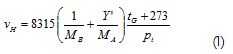
Where:
MA, water molecular weight = 18.02 g/mol
MB, air molecular weight = 28.97 g/mol
tG, air temperature in °C = 20°C
Pt, total pressure in Pa = 74,660.5 (Bogotá's barometric pressure)
vH, wet volume in mix m3/air kg
Volumetric flow calculation
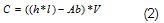
Where:
C, volumetric flow in m3/s
h, tunnel height from the drying chamber in m
l, tunnel width from the drying chamber in m
Ab, cross-sectional tray area in m2
V, tunnel air speed in m/s.
Mass flow calculation
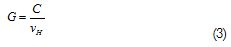
Where:
G, dry air mass flow to be cooled in kg/s
C, volumetric air flow in m3/s
Heat removal calculation
This was determined by using the following equation from the energy balance:
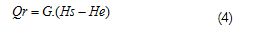
Where:
Qr, heat removal from air in kJ/s
Hs, out enthalpy from air in kJ/dry air kg
He, in enthalpy from air in kJ/dry air kg
G, mass flow of dry air in kg/s
All these equations were taken from Treybal (Treybal, 2000).
Heat exchanger area
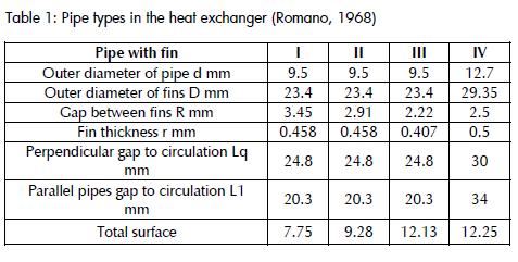
This was determined by using the following equation and table.
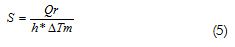
Where:
S, heat exchanger area in m2
Qr, heat removal from air in kJ/s
h, heat transfer coefficient (forced convection)in W/m2K
ΔTm, mean logarithmic difference between refrigerant and air in K
The heat transfer coefficient was fixed as 19 Kcal/h.K.m2 or 22 W/m2.K according to air speed and type of heat exchanger from the supplier's table. The equation was taken from Romano (Romano, 1968).
Compressor work
This was stated using the energy balance in the compression stage of a typical mechanical refrigeration cycle.
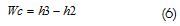
Where:
Wc, work supplied by the compressor in kJ/ refrigerant kg
h3, enthalpy after compression in kJ/refrigerant kg
h2, enthalpy before compression in kJ/ refrigerant kg
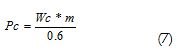
Where:
Pc, compressor power in kW
m, mass flow in kg/s
0.6, compressor efficiency.
The temperature at the compressor entry was fixed at 4.5°C and 32.2°C at the exit. R-12 refrigerant was used.
The equations were taken from Roy (Roy, 2001).
Heating system
Electric fin resistance was used to heat the air to improve heat transfer and arranged in such a way that airflow was always crossed. It was calculated by the following equation:
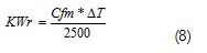
Where:
KWr, kilo watts required by resistance
Cfm, air cubic meters per minute
ΔT, temperature interval in Fahrenheit
The equation was taken from Omega Engineering Product Manuals - Heaters (1995).
Humidifying system,
The humidifying system consisted of a water tank heated by electric resistance. The resistance supplied the energy required for evaporating the amount of water necessary to humidify the air. Resistance power was calculated by taking into account the amount of water required to reach the upper limit of reviously-established humidity (Bogotá's environmental conditions).
Where:
Bevap, amount of water to be evaporated in kg/s
G, air flow mass in dry air kg /s
Ys, absolute humidity at the humidifier system's water exit in kgldry air kg
Ye absolute humidity at the humidifier system's water entry in kgldry air kg
Where:
PH, power of immersion resistance kJ/s
ΔH, latent heat of evaporation in kJ/water kg, 15% loss
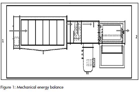
Air propulsion system
The air propulsion system was calculated by mechanical energy balance in the dryer (points 1 and 2) for non-compressible f1uids, because the air density in the equipment did not change conside¬rably. The selected system can be seen in Figure 1.
Losses in straight pipelines
These were calculated by using the following equation:
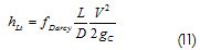
Where:
hLt, losses in straight pipelines in J/kg
fDarcy,, Darcy's friction factor (frorn Moody's diagram)
L, piping length in m
D, equivalent diameter in m
V,, air speed in m/s
gc1 kg. m. N/s'
Losses in accessories
The following equation was used to estimate losses in accessories:
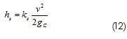
Where:
hs, losses in obstacles or accessories in J/kg
ks loss coefficient (depending on the case)
v speed in m/s
gc1 kg.m.N/s'
- Loss coefficient in abrupt expansion
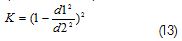
Where:
d1, small section diameter in m
d2, large section diameter in m
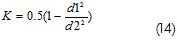
- Loss coefficient in abrupt contraction
- Loss coefficient in 90° angle. K = 1.25
Previous equations were taken from Crane (1987).
Losses in heat exchangers, dehumidifying section
The losses in heat exchangers were stated according to the following equation:
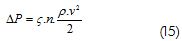
Where:
ΔP, pressure drop in (N/m2)
ς,, resistance coefficient
n, number of pipe rows in the direction of flow
ρ,. densítykg/m3.
v, air speed in m/s.
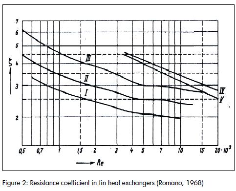
The equation was taken from Romano (1968).
The resistance coefficient was determined using Table 1 and Graph 1 from Figure 2 Type 3 pipe was assumed because of its dimensional similarity with the heat exchanger designed and it was estimated by interpolating the Reynolds number (equivalent diameter and hydraulic radius) and calculating as shown in the Graph from Figure 2.
Control strategy and instrumentation
Figure 3 shows the piping and instrumentation diagram (P&IO) for the equipment with control system, indicators, controller and sen¬sor location in the drying system so designed
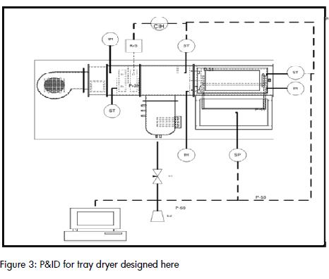
This allowed doing energy and mass balances and ensuring better knowledge appropriation by students.
The equipment has data acquisition cards, allowing solid weight to be recorded during a desired period of time and saved on an Excel sheet. Water and air temperature was controlled by a dosed con¬trol loop with feedback. Equipment response could vary, modi¬fying resistance turn-off time according to equation 16.
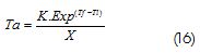
Where:
Ta: turn-off time in seconds
Tf: temperature set point in oC
TI: temperature reading in oC
K y X: adjustment constants
Constants K and X were established according to the system's dynamic response to minimise response time. Typical values found for obtaining a good answer were K=5 and X=4.
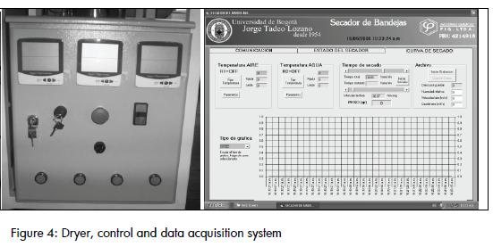
The strategy used for changing the airflow consisted of varying pressure drop using a damper located in the initial section. Air speed was modified by using a digital pocket anemometer located at the drying chamber exit. Figure 4 shows the drying system, the control and data acquiring system in real-time (Excel),
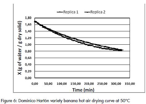
Equipment start-up and validation
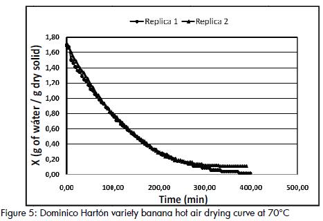
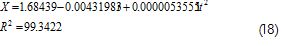
The different instruments and sensors were calibrated and control strategy effectiveness verified to start the system up. Drying curves were made in duplicate to validate the equipment, using the Do-minico Hartón variety banana at 70°C and 50°e. The drying cur¬ves were modelled with a polynomial. The curves so obtained are shown below.
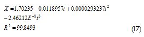
Figure 5 shows the curves obtained at 70°e. The system's high le¬vel of reproducibility, once designed and built, can be seen by comparing the two replicas evaluated. A mathematical model was also obtained which related humidity with time in the stated con-dition; this model was well adjusted to the real data. The model can be seen below
Conclusions
A semiautomatic tray-dryer characterised by high versatility and re-producibility was designed and built. It allowed drying curves to be constructed at different temperature, humidity and air speed con-ditions, thereby supporting teaching and research.
The control software so designed led to easy manipulation of the variables to be controlled with a user friendly interface; it could al¬so acquire data in real-time through a computer interface.
The polynomial model using Excel predicted the behaviour of the drying curves for the Dominico Hartón variety banana at 50°C and 70ce with 0.07% error regarding the experimental data.
Acknowledgements
We would like to thank the Research Division at the Jorge Tadeo Lozano University in Bogotá for sponsoring this research project and Industrias Químicas FIQ Ltda for building the equipment and supporting the controllogistics
Crane, División de Ingeniería., Flujo de Fluidos en Válvulas, Accesorios y Tuberías., McGraw–Hill (ed.), México, 1987, pp. 3. [ Links ]
Maestre, A., Melgarejo., Curso de Ingeniería del Frío., 2a ed., Vicente Ediciones, Spain, 1993, pp. 222. [ Links ]
Omega Enginnering Product Manuals., High Temperture Air Duct Heater., 1995, pp. J-5. [ Links ]
Roy, E., Dossat., Principios de Refrigeración Mecánica., 2nd ed., Compañía Editorial Continental, México, 2001. [ Links ]
Treybal, E., Robert., Operaciones de Transferencia de Masa. 2nd ed., Mc Graw Hill, México, 2000, pp. 723-739. [ Links ]
Vargas, E., Garzón, F., Construcción de equipos para apoyo docente para ingeniería química: una alternativa de aprendizaje integral., Revista de Ingeniería de la Universidad de los Andes, Vol. 20, 2004, pp. 80 – 83. [ Links ]

