


Serviços Personalizados
Journal
Artigo
 texto em
  Espanhol (pdf)
 Artigo em XML
 Referências do artigo
 Enviar este artigo por email
Indicadores
-
 Citado por SciELO
 -
 Acessos
Links relacionados
-
 Citado por Google
 -
 Similares em
SciELO
Similares em
SciELO -
 Similares em Google
Compartilhar

 Permalink
Ingeniería e Investigación
versão impressa ISSN 0120-5609
Ing. Investig. v.30 n.2 Bogotá maio/ago. 2010
EMI filter techniques in power electronic converters
Fredy Edimer Hoyos Velasco1, Camilo Younes Velosa2 and Eduardo Antonio Cano Plata3
1 Electrical Engineer. M. Sc., in Engineering - Industrial Automation Line. Ph.D. Student, en Automatic Engineer, Universidad Nacional de Colombia, Manizales,Colombia. Member, Grupo de investigación PCI, Universidad Nacional de Colombia, Manizales, Colombia. fehoyosv@unal.edu.co 2 Electrical Engineer, M. Sc., Electrical Engineering, Ph. D., Electrical Engineering, Universidad Nacional de Colombia, Bogotá, Colombia. Associate Professor, Member, Grupo de investigación GREDyP, Universidad Nacional de Colombia, Manizales. Colombia. cyounesv@unal.edu.co 3 Electrical Engineer. Electromagnetic Transient Specialization, Universidad Nacional de San Juan. Specialization Electrical Engineering, Universidad Nacional de Colombia, Manizales, Colombia. Ph. D., in engineering, Universidad de Buenos Aires, Argentina. Associate Professor, Member, Grupo de investigación GREDyP, Universidad Nacional de Colombia, Manizales Colombia. ecano@ieee.org
ABSTRACT
This paper presents the results of EMI reduction techniques applied to power electronic converters. The techniques applied included shielding control and power signals, separating power system references regarding reference for instrumentation and measurement signals, implementing analog filters and configuring an appropriate switch trigger system for electronic power to decrease shifting EMI emissions to the maximum. This paper presents the results before and after applying the techniques to reduce interference. The results were also verified by using two real time control strategies rapid control prototyping (RCP). Keywords: EMI reduction, DSP, power electronic converters, shielding, rapid control prototyping (RCP).
Keywords: EMI reduction, DSP, power electronic converters,shielding, rapid control prototyping (RCP).
Received: jun 24th 2009
Accepted: jun 11th 2010
Introduction
Electromagnetic interference (EMI) has gained importance due to the constant increase of electronic charges. The situation has been aggravated by circuits' increased integration density of (Josep Balcells et al., 1992).
More jobs and processes can now be done more efficiently, safer and at lower cost using advances in digital and power electronics. Recent studies (Huibin Zhu and J.S. Lai, 1999), (Chingchi Chen, 2003), (Paul C. R and Hardin K. B, 1998), (Ran L and Gokani S, 1998) have shown that high dv/dt and di/dt are responsible for most conducted emissions. Electronic converters perform in transient regime, switching voltage currents between different circuit branches, resulting in the generation of harmonics, local surges, power peaks, high dv/dt and di/dt, which in turn generate EMI interference affecting their own supply, the connected receivers, the supply circuits and the circuits receiving radiation disturbance (Josep Balcells et al., 1992).
Conducted and radiated EMI might be generated. Many conclusions have been drawn and many kinds of filters have been proposed for minimising their effect. Kim and Sul have proposed a differential mode filter (SJ Kim and SK Sul, 1997) and Ogasawara and Akagi have proposed a common mode filter (S. Ogasawara and H Akagi 2001).
Industrial and technological world-wide applications require high-quality electrical energy, otherwise the equipment will suffer significant damage to its internal components, data loss and data errors. It is estimated that 90% of electrical energy is processed through power converters (FG Angulo 2004). Electronic systems, sensitive to EMI, consume about 1% of all produced energy and the other 99% are mainly used in lighting, electric motors and heating systems (Francesc Daura, 1987), (IEEE, 1982). The vast majority of EMI affecting equipment and their surroundings is produced during these processes.
This paper presents EMI phenomena characteristic of switching power supplies. For this case a single-phase ondulator was controlled using simulink by rapid control prototyping (RCP). Some EMI reduction techniques were implemented, among them analog filters, land management, screening and distribution of the components to be interconnected. The results are shown before and after these techniques were applied.
The converter being studied
The design of the converter being studied is shown in Figure 1. It has switching, an LC filter and feeding load which is a pure resistive load (R). It begins with non-regulated voltage (E) at the entrance. A regulated, variable frequency and width exit was achieved through modulating PWMC width pulses at a constant frequency of up to 20 kHz.
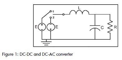
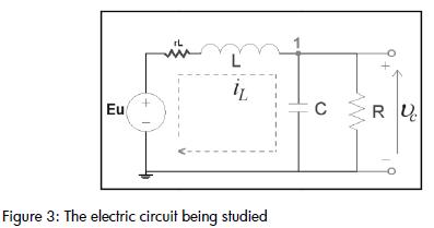
The switching was located in 1 or 2 depending on the control signal as shown in Figure 2, where outputs d, PWMC and PWMCinv can be seen. These control signals were responsible for controlling the time that each of the sources would be connected to the filter. Figure 3 shows a simplified diagram of the converter. The signals needed to implement control techniques were taken from the converter. Among them, were inductor current (iL), voltage on the capacitor (Vc) and the current in the load (iR). These signals, along with the Vref reference signal, were digitally processed in an appropriate platform, in this case a control and development card (dspace, 2009), (DS1104 controller board, 2005), (DS1104 features, 2005), (DS1104 RTI reference, 2005), (DS1104 RTLib reference, 2005).
.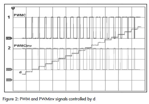
If the reference signal was sinusoidal, then the converter would behave as DC-AC, but if it were continuous, then the converter would behave as DC-DC. Figure 2 shows the control signals which indicated the time that the +E o -E supply would be connected to the filter. The period of time T in which the supply +E was connected was called the work cycle (d). The presence of PWM generated a control signal which allowed the modeling of the system as a variable structure because each time the control signal changed it switched from one topology to another. The system could then be replenished through high frequency control pulses to activate + E o -E at the entrance to feed the converter, which would decrease the difference between real Vc voltage and Vref reference voltage.
System modeling
The model in system state variables as follows:
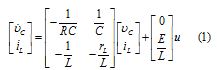
Where capacitor voltage (Vc) and inductor current (iL) were the state variables.
The control variable (u) took discrete values +1 and -1. The system is represented as in (2) for better operation of the equations.
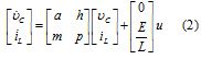
Where: 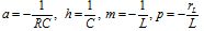
This system can be represented as  .
.
Real knowledge about state variables, such as condenser voltage (Vc), inductor current (iL) or load current (iR) was needed to control this system in case complex loads were to be connected. However, these signals should not have been contaminated with EMI from the same or any other nearby equipment.
Figure 4 shows the inverter bridge operating the power circuit. It is worth noting that a floating ground was needed if the aim was to control the switch using a DSP card.
EMI reduction techniques applied to the converter being studied
This section describes proper device connection and signal conditioning coming in or going out of the control card to minimise EMI to the maximum. It is important to note that this can be applied to any other smart digital devices such as FPGA, microcontrollers, microprocessors, DSPs, control and development cards, and acquisition and control cards. Return, power, shield and grounds signals are very often called ground signals (DS1104 controller board, 2005), (DS1104 features, 2005), (DS1104 RTI reference, 2005), (DS1104 RTLib reference, 2005).
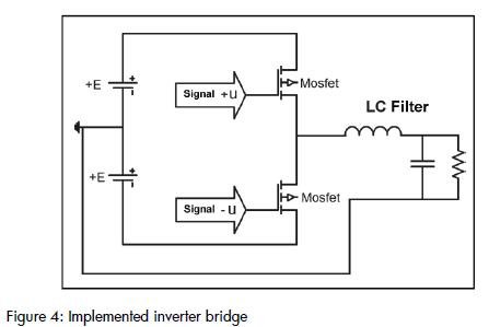
The different ground signals had not to be combined if the aim were to improve the results regarding signal quality, noise rejection and electromagnetic behavior. The return signal line corresponding to the reference signal to be lead had the same signal current and was usually of low value. The ground for the power signal was the way back for the electric power supply, and had a great amount of energy, usually alternating energy. The shielding was a barrier to protect the signals therein. It was usually connected to the power equipment and it was not necessary to be connected to the ground for the system. The ground protection was the ground system designed to protect the equipment and the users. The correct connection of external signals (Vc, iL, iR) coming from the real system was accomplished based on Figure 5 Each signal had to be brought from the outside to the card using a shielded twisted pair cable with the shield grounded through the card. It was necessary to avoid connecting the shielding to the card's GND pins.
It is recommended that a return line be used for each signal and brought to the card using a shielded twisted pair cable as this protects the signal against EMI, has low inductance and also cancels electromagnetic parasite fields.
To perform a comprehensive shielding of the system where all signals and devices are protected, it was necessary to enclose the system in a Faraday cage, as it has low resistance and particularly low inductance.
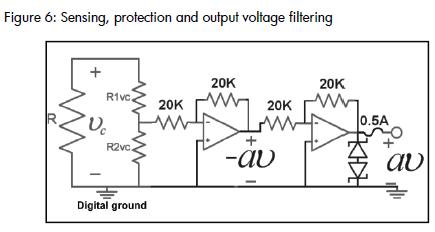
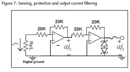
Several types of analog filters were implemented using operational amplifiers and passive elements, such as resistance and capacitance.
Figures (6) and (7) show the assembly implemented using the operational amplifiers. Circuits needed for protection against surges in the voltage and the current were added using 9-volt zener diodes and a 0.5 Amp fuse.
Results
This section presents the results obtained before and after applying the techniques mentioned above.
Figure 8 shows the PWM control signal, the power PWM signal and the current signal (iL), which in this case was the one affected by the electromagnetic interference produced by the switching of the transistors.
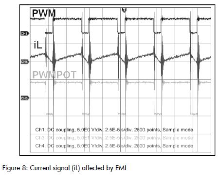
Figure 9 shows the voltage signals on the load (Vc) and the inductor current (iL). EMI phenomena were present due to high dv/dt which were transmitted to the variables. If the control to be implemented required these system states in real time then signals should be filtered, otherwise the technique would not have had efficient performance.
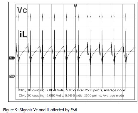
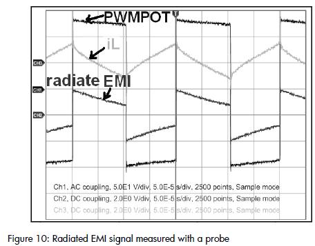
Figure 10 shows a + / -130 volt PWM power signal switching to 5kHz, the current in the inductor iL and also the radiated noise signal (detected with a probe located 1 cm from the switching). It was found, experimentally, that as the radiated noise moved away from the interference source, in this case the switches, it decreased, and that this noise was the one interfering with the sensing signals and in general with the entire circuit. The radiated signal thus affected the proper performance of the control cards. Figure 10: Radiated EMI signal measured with a probe Figure 11 shows the improvement in noise reduction after applying the noise suppression techniques described above. The top shows the power PWM signal, the voltage output on the load (Vc), the current in the inductor (IL) and the current on the load (iR). All of them had almost complete noise reduction due to the switching.
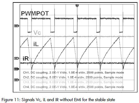
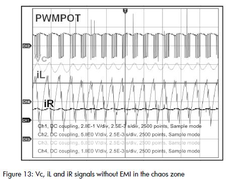
Figures 12 and 13 show the same signals but with low level radiated EMI. Figure 12 shows signals that are periodic (of period 6) and Figure 13 shows the signals entering the chaos zone. It should be considered that these signals were free of EMI and they could be used to implement a better real time control action.
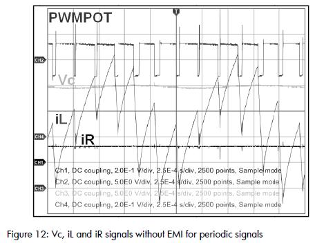
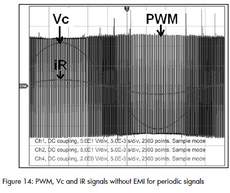
Figura 14 taken from (Hoyos F.E, 2008), shows the performance of the zero average dynamics (ZAD) control technique (F Angulo, 2003), (Angulo F, et al., 2008), (Taborda J, et al., 2007), working in conjunction with the control of fixed point induction (FPIC) control technique (Angulo F, et al., 2007) (Olivar G, et al., 2005),
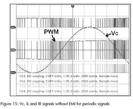
Once the EMI were reduced to the maximum, another control technique (control with hysteresis) was applied, (Angulo F, 2007), (Hoyos C, et al., 2007), (Angulo F, et al., 2007), where it was essential for the sensing signals to be EMI-free. Figure 15 shows the performance of the control from a DSP card in real time, with reference 40sen (2π 10t).
Conclusions
EMI produced by the converter being studied became greatly reduced when using noise suppression techniques.
The control techniques were efficiently applied once the vast majority of EMI were eliminated. Also, an enhancement in control technique performance was observed in real time.
Some considerations should be taken into account.
- Analog and digital lines should be kept separated.
- Connectors in unprotected panels (belts) should not be used in areas of high electromagnetic radiation.
- A shielded twisted pair cable should be used to carry signals from the outside to the card so each signal is carried out to a pin and sent back through the return signal. The signals should be shielded.
-Whenever possible, short cables should be used between the outside and the card.
- Signal lines should not be placed together with power lines. These lines may run parallel but with an adequate distance between them to reduce magnetic coupling.
- The signals should be protected against equipment and devices producing magnetic fields such as cell phones, transformers, coils, power supplies, electric motors and screens.
Acknowledgements
We would like to thank Professor Fabiola Angulo Garcia; without her support it would have been very difficult to complete this research.
Angulo, F. G., Análisis de la dinámica de convertidores electrónicos de potencia usando pwm basado en promediado cero de la dinámica del error (ZAD)., PhD dissertation, Universidad Politécnica de Cataluña, Cataluña, Spain, 2004. [ Links ]
Angulo, F., Desarrollo de una nueva técnica de control para sistemas discretos., Work presented for becoming promoted to fulltime Professor, Universidad Nacional de Colombia, Manizales, Colombia, October 2006. [ Links ]
Angulo, F., Hoyos, C., Olivar, G., Dinámica de un Convertidor Buck Controlado en Tensión por banda de Histéresis Constante., Segundo Simposio Regional Electrónica y Aplicaciones Industriales, 2007. [ Links ]
Angulo, F., Hoyos C., Olivar, G., Caracterización estadística del convertidor Buck en régimen caótico., 3rd International Electrical and Electronic Engineers Congress, 2007, Bogota. [ Links ]
Angulo, F., Olivar, G., Taborda, J., Hoyos, F., Nonsmooth dynamics and FPIC chaos control in A DC-DC ZAD-strategy power converter., Sixth Euromech Nonlinear Dynamics Conference (Enoc 2008), Vol. 55, Saint Petersburg, 2008, pp. 2392–2401. [ Links ]
Balcells, J., Daura, F., Esparza, R., Pallás, R., Interferencias Electromagnéticas en sistemas Electrónicos, Barcelona Spain, 1992. [ Links ]
Chingchi, Ch., Characterization of power electronics IEM emission., IEEE Electromagnetic Compatibility Conf, pp. 553-557. 2003. [ Links ]
DS1104 Controller Board., RTLib Reference, dSPACE, Release 5.0 – November, 2005. [ Links ]
DS1104 Controller Board., dSPACE, Hardware Installation and Configuration, For DS1104 and CP1104 CLP1104 Connector Panels, Release 5.0 – November, 2005. [ Links ]
DS1104 Controller Board., Features, dSPACE, Release 5.0 – November, 2005. [ Links ]
DS1104 Controller Board., RTI Reference, dSPACE, Release 5.0 – November, 2005. [ Links ]
Francesc, D. L.,. El ruido en sistemas digitales I., Mundo Eléctrico No. 175, 1987. [ Links ]
Hoyos, C., Olivar, G., Avendaño, L., Bifurcation analysis, instrumentation and voltage control in buck converter regulated by hysteresis band., CARS and FOF 2007, Bogota, 2007. [ Links ]
Hoyos, C., Osirio, G., Control por modos deslizantes, diseño e implementación, aplicado a un convertidor Buck., Simposio internacional sobre calidad de la energía eléctrica, Manizales, 2007. http://www.dspace.com/ww/en/pub/start.cfm, Embedded Success dSPACE, Accelerating your success. [ Links ]
Hoyos, F. E., Desarrollo de Software y Hardware para Manejo de un Convertidor DC-DC y DC-AC Controlado con ZAD y FPIC., MSC thesis, Universidad Nacional de Colombia, Manizales, 2008. [ Links ]
Huibin Z., Lai, J. S., Analysis of conducted IEM emissions from PWM inverter based on empirical models and comparative experiments., IEEE PESC 99, 2(27), 1999, pp.1727-1733. [ Links ]
IEEE Guide for the Installation of Electrical Equipment to Minimize Electrical Noise Inputs to Controllers from External Sources., IEEE Std 518, 1982. [ Links ]
Kim, S. J., Sul, S. K., A novel filter design for suppression of high also eliminate a small part of CM noise., Voltage gradient in voltage-fed PWM inverter, IEEE Proceeding Applied Power Electronics, 1997, pp. 122-127. [ Links ]
Ogasawara, S. Akagi, H., Suppression of common-mode voltaje in a PWM rectifier/inverter system., IEEE Industry Applications, Conference 2001, pp. 2015-2021. [ Links ]
Olivar, G., Ocampo, C., Angulo, F., Fossas, E., Stabilization of chaos with fpic: Application to zad-strategy buck converters., 16th IFAC World Congress in Prague, 2005. [ Links ]
Paul , C. R., Hardin, K. B., Diagnosis and the common mode and differential mode conducted IEM noise., IEEE Trans, Electromagnetic Compatibility, 1998, pp. 553-560. [ Links ]
Ran, L., Gokani, S., Conducted electromagnetic emission in induction motor drive systems part I: time domain analysis and requirement, should be met identification of dominant modes., IEEE Trans. Power Electron, 1998, pp. 757-767. [ Links ]
Taborda, J., Hoyos, F., Hoyos, C., Perez, E., Diseño e Implementación de un Inversor Monofásico Usando una Topología buck, IV Simposio Internacional sobre Calidad de la Energía Eléctrica (Sicel 2007), Manizales, 2007. [ Links ]

