


Serviços Personalizados
Journal
Artigo
 texto em
  Espanhol (pdf)
 Artigo em XML
 Referências do artigo
 Enviar este artigo por email
Indicadores
-
 Citado por SciELO
 -
 Acessos
Links relacionados
-
 Citado por Google
 -
 Similares em
SciELO
Similares em
SciELO -
 Similares em Google
Compartilhar

 Permalink
Ingeniería e Investigación
versão impressa ISSN 0120-5609
Ing. Investig. v.30 n.3 Bogotá set./dez. 2010
Dorian Luís Linero Segrera1, Javier Oliver2 y Alfredo E. Huespe3
1 Civil Engineer. M.Sc., in Struture. Ph.d., in Structural Analysis, Universidad Politécnica de Cataluña, Spain. Professor, Faculty of Engineering, Universidad Nacional de Colombia, Bogotá. dllineros@unal.edu.co
2 Civil Engineer. Ph.D., in Civil Engineering, Universidad Politécnica de Cataluña, Spain. Professor, Department of Strength of Materials and Structures, Universidad Politécnica de Cataluña. Spain. oliver@cimne.upc.edu
3 Mechanic and Electrical Engineer. M.Sc., in Science of Enginnering. Ph.D., in Science of Enginnering, Universidad Federal de Rio de Janeiro, Brasil. Researcher, CIMEC/Intec - CONICET, Santa Fe, Argentina. ahuespe@intec.unl.edu.ar
ABSTRACT
The numerical simulation results of the fracture process in re-inforced concrete shear panels are presented in this work. The simulation used a model based on the continuum strong dis-continuity approach (CSDA) and mixing theory. CSDA des-cribes strain localization and formation of discontinuity asso-ciated with the appearance of a crack. On the other hand, mixing theory represents composite material behaviour which is formed by a simple concrete matrix and one or two bundles of long reinforcement bars. The behaviour of simple concrete and steel is represented by a two dimensional damage model and one-dimensional plasticity model, respectively. The model has been implemented in the finite element method which considers plane stress, infinitesimal strain and static loads. Three panels are simulated, reinforced in one or two ways; they are mainly subjected to shear forces. The numerical si-mulation results as well as structural response and cracking patterns were satisfactory.
Keywords: Computational mechanics, fracture mechanics, strong discontinuity, mixing theory, reinforced concrete, finite elements, Shear panels.
Received: february 16th 2009
Accepted: november 15th 2010
Introduction
Reinforced concrete walls are an important part of current struc-tural systems, mainly due to their capacity to resist shear stress when seismic or wind action takes place. When loads are applied and following the elastic regime, reinfor-ced concrete elements exhibit a decrease in their stiffness simulta-neously with crack formation and propagation. Such behaviour has been represented by the numerical model developed by the au-thors in previous work (Linero, Oliver et al. , 2007; Linero, Oliver et al. , 2010). The model has been used in this article to simulate three panels subjected to shear.
The numerical model considers that reinforced concrete is a com-posite material formed by a simple concrete matrix and one or two bundles of steel reinforcement bars. According to mixing theory (Oller, 2003), the constituent materials remain under common strain whereas composite material stress is equal to the weighted sum of the stress of each component.
The stress-strain relationship of simple concrete and steel are re-presented by a two-dimensional damage constitutive model and one-dimensional plasticity model, respectively (de Souza, Peric et al. , 2008).
A crack appears at a place where displacement shows discontinuity and the strain grows without bounds. On the other hand, strain remains a bound value outside the fracture zone. This phenomenon is named strain localization and is represented in the numerical model by the continuum strong discontinuity (CSD) approach (Oliver and Huespe, 2004b; Oliver and Huespe, 2004a; Oliver, Huespe et al. , 2006).
The model has been implemented in the finite element method for problems with plane stress, static loads and non-linear material.
Reinforced concrete behaviour
Reinforced concrete fracturing
The mechanical behaviour of reinforced concrete shows four sta-ges associated with crack appearance, formation and distribution in simple concrete. The typical response of panels subjected to pu-re tension (Ouyang, Wollrab et al. , 1997) and pure shear (Bhide and Collins, 1989) is summed. The reinforcement bars are homo-geneously distributed throughout the whole panel.
The concrete is not still cracked during the first load steps and the behaviour of both materials is linear elastic, as shown by line OA in the load-displacement curve in Figure 1.
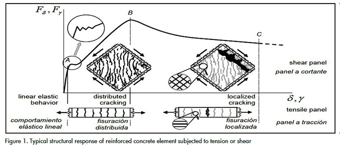
The first crack in the concrete is formed near point A on the curve, producing local redistribution of stress until the almost immediate appearance of a new crack. This short phase is named crack formation stage.
The appearance of new cracks is limited by the ability to transfer stress between the reinforcement and the concrete in the distribu-ted cracking stage. If adherence between both materials is good, then cracks will appear until the so-called saturation condition is reached in which many cracks having small openings and constant spacing are propagated, as shown in line AB in Figure 1.
When the steel reaches its elastic limit or the bars slip regarding the surrounding concrete, the opening of one of the cracks (or sometimes two or three) is imposed with respect to the others. This defines a localized crack stage, as shown by line BC. This stage is extended until the capacity of steel reinforcement in the plastic range allows it
Interaction phenomenon between concrete matrix and steel bars
The most important interaction phenomenon between concrete cracks and steel bars are adherence loss and dowel action, as indicated below.
Adherence between the concrete matrix and the steel bars is mainly defined by friction between both materials, depending on the geometrical characteristics of a steel reinforcement surface. Corrugated rods thus give high adherence capacity because of interlocking between the reinforcement ribs and the surrounding concrete (Nawy, 2008; Wight and MacGregor, 2008). Adherence loss is related to different mechanisms such as concrete crushing in front of each rib, the appearance of horizontal cracks at the ends and the presence of secondary transversal cracks. The most significant of the three mechanisms inducing adherence loss is secondary crack formation which forms near primary cracks and has radial propagation away from each rib of the corrugated bars, as illustrated in Figure 2(a).
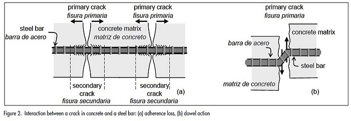
When stress produces displacement parallel to the face of a crack, as illustrated in Figure 2(b), part of the shear stress is supported by internal interlocking amongst the aggregate particles of concrete. However, the most important contribution is the shear capacity of the cross-section of the steel bars crossing the face of a crack; this phenomenon is known as dowel action and is common in panels subjected to shear (Nawy, 2008; Wight and MacGregor, 2008).
Numerical simulation of reinforced concrete panels subjected to shear
Before the simulation, a special reinforced concrete model having strong discontinuity had been implemented in the finite element method (Linero, Oliver et al. , 2007; Linero, Oliver et al. , 2010), which considers linear triangular elements, plane stress, infinitesimal strain, static loads and non-linear material.The code was written in FORTRAN language, using open-code computational COMET software (Cervera, Agelet et al. , 2002).
Several experimental tests of reinforced concrete shear panels as carried out by some other researches were simulated (Collins, Vecchio et al. , 1985; Bhide and Collins, 1989). It is valid to suppose for this type of problem that reinforced concrete is a composite material formed by steel bars which are uniformly distributed in a concrete matrix.
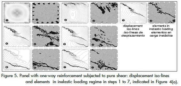
The next three aspects are important in analysing numerical simulation results. First, loading states' cracking paths are defined by displacement iso-lines. Cracks form because of strain localization, appearing where there is the least spacing between two displacement iso-lines. Secondly, strain in inelastic loading increases at the material point where equilibrium bifurcation takes place whereas strain in elastic unloading decreases at a nearby point and maintains traction continuity. The elements in inelastic loading surrounded by unloading areas are thus an indicator of the cracking area. Thirdly, when many parallel cracks are uniformly distributed there is no obvious localization on the study scale. In this case, numerical simulation will show inelastic loading on the whole specimen and constant spacing between displacement iso-lines.
Panel with one-way reinforcement subjected to pure shear
The numerical simulation results of a panel having one-way reinforcement subjected to pure shear are presented. The panel corresponds to Bhide and Collins' test PB18 (Bhide and Collins, 1989).
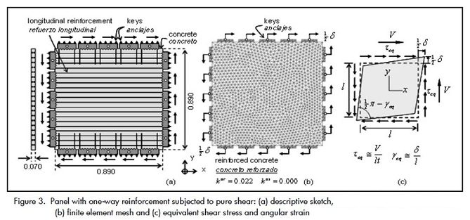
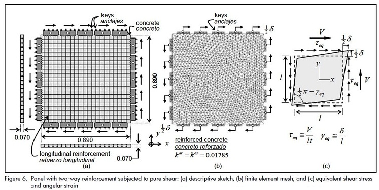
A square panel (length l=890 mm and thickness t=70 mm) was reinforced with 40 6mm diameter bars in x-direction consisting of 2.2% of the panel's total volume. As Figure 3(a) indicates, the shear force was applied in xy-plane by means of a set of 5 keys in each side which were joined to concrete and steel.
The simple concrete had Ec= 20 GPa Young's modulus, Vc= 0,2, Poisson ratio, Gf= 100 N/m fracture energy, σct= 2 MPa tensile strength and σcc= 20 MPa compressive strength. The reinforcement steel bars had perfect elastic-plastic behaviour with Ea= 200 GPa Young's modulus and σy= 402 MPa yielding stress.
Numerical simulation supposed high adherence between the concrete and steel bars, as well as a considerable effect of dowel action characterised by Ga=Ea/2(1+va)= 83.33 GPa equivalent shear elastic modulus and τy=σy/√3= 263.3MPa equivalent shear yielding stress.
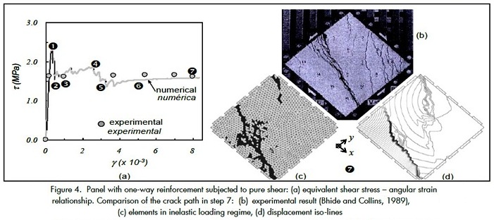
A 2,736 triangular linear finite element mesh was used, as shown in Figure 3(b). The dark gray represents the loading application keys and the bright gray corresponds to reinforced concrete elements. The latter elements were formed by 97.8% concrete matrix and 2.2% steel bars in x-direction. Displacement by key was imposed in the numerical model, generating overall pure shear state over all the panel, as indicated in Figure 3(c). Structural response was represented by means of the relationship between equivalent angular strain Yeq=δ/l and the equivalent shear stress on one of the faces of the panel, which was obtained from adding reactions in the keys divided by the area of the face panel, τeq=V/lt. Figure 4(a) shows that the proposed numerical solution differed from experimental response peak load; however, the rest of the curve indicated a satisfactory approach. Such differences could be caused by some boundary conditions involved in the actual problem which were neglected in the numerical model.
The concentration bands of displacement iso-lines and inelastic loading regime in Figure 5 represent the presence of discontinuity. Dark gray elements represent inelastic loading regime and bright gray elements represent elastic unloading regime.
A photograph of the panel being tested in Bhide and Collins' work is shown in Figure 4(b) (Bhide and Collins, 1989). This experimenttal result was compared to finite elements in inelastic loading and displacement iso-lines obtained from the numerical simulation in loading step 7, as shown in Figure 4(c) and (d). Due to the homogenous nature of the test, the initial cracking point was supposed at random; the discontinuity represented in step 7 of the numerica simulation was therefore considered correct because it was parallel to the experimental crack, despite its position in the panel.
Panel with two-way reinforcement subjected to shear
The PV27 square panel tested by Collins, Vecchio and Mehlhorn (Collins, Vecchio et al. , 1985) was simulated. This panel was 890mm long and 70mm thick and was reinforced with 40 steel bars in x-direction (corresponding to 1.785% of the panel's total volume) and 40 bars in y-direction, in the same ratio. Figure 6(a) shows a sketch of the problem and Figure 6(b) and Figure 6(c) describe the application of the loads.
This test's concrete and steel mechanical characteristics and those of the previous test were equal. The results with a 2,736 element mesh are described and compared to experimental values.
The equivalent shear stress-angular strain relationship applied to the panel is shown in Figure 7(a), where the solid line represents the numerical result and the dashed line the experimental values. The inelastic loading elements and the displacement iso-lines for the load step indicated in Figura 7(a) are shown in Figura 8(a) and Figura 8(b).
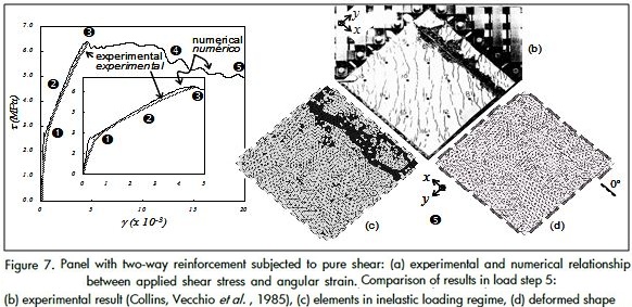
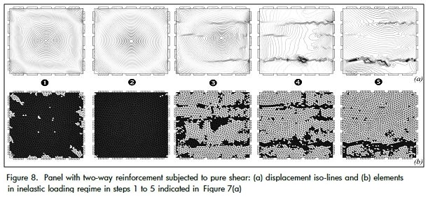
Figure 7(b) shows the test cracking path indicated in Collins, Vecchio et al. , (Collins, Vecchio et al. , 1985).
An inelastic loading state was observed in the whole panel without strain localization during steps 1 and 2; this meant that despite the damage in the matrix, the displacement jump field was not activated. Many cracks were observed in the main direction, having small openings and being distributed over the whole panel during this phase of the test.
Strain localization in three areas of the specimen began in step 3. Only two cracks appeared in step 4 and a single discontinuity in the final step in x-direction at the bottom of the panel. The test indicated that the main crack was also parallel to x, but was produced at the top of the specimen. Due to the test's pure shear condition it was considered that this crack could present any panel height.
Panel with one-way reinforcement subjected to normal and shear forces
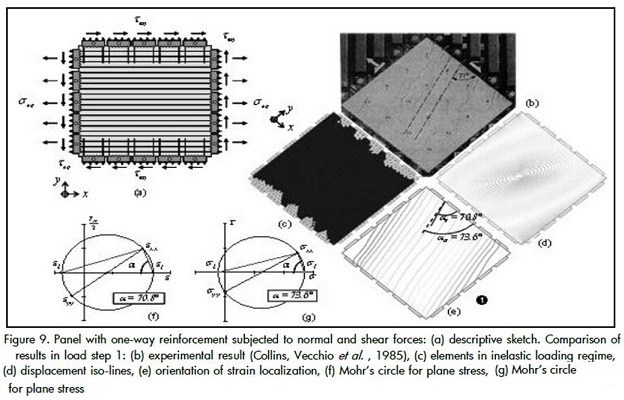
The results of the numerical simulation of a panel having reinforcement in x-direction are presented; it was subjected to shear stress τeq and normal stress σeq=3.1τeq in x-direction. The panel had the same geometry, mechanical properties and finite element mesh as indicated in Section 3.1, but its applied load had changed, as shown in Figure 9(a).
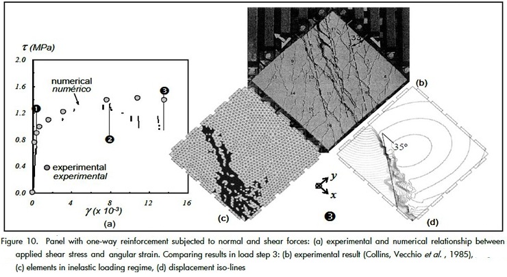
Structural response was represented via the relationship between average angular strain and equivalent shear stress, as shown in Figure 10(a). Good correlation was obtained between numerical and experimental results, exceptin the latest load steps, possibly because of differences among the actions of the keys on the panel.
Step 1 of the test consisted of a distributed cracking state in which several cracks were observed distributed throughout the whole panel and orientated 71° with respect to the x-axis, as indicated in Figure 9(b). This stage was described in the numerical simulation, giving the following results: (1)Figure 9(c) indicates inelastic loading of damage in the concrete on almost all the elements of the panel, (2) Figure 9(d) shows an almost constant spacing between displacement iso-lines, indicating the absence of strain localization and (3) Figure 9(e) shows that the orientation of strain localization coincided with the direction of the maximum main strain throughout the whole panel (70.8° regarding x-axis).
The composite material's orthotropic behaviour was induced by the presence of bars orientated in x-direction. This meant that the main direction of stress and strain were not exactly the same as in Mohr's circle, shown inFigure 9(g) and Figure 9(f).
Strain localization was produced in step 2, with very little stability of structural response, as shown in Figure 10(a). The discontinuity path in load step 3 was represented by the concentration of displa-cement iso-lines in Figure 10(d) and the elements in inelastic loa-ding of damage in Figure 10 (c). Such numerical result was similar to the main crack path in the test (Figure 10 (b)), with a difference of 2° between crack orientations. However, the structural response was a bit far from the experimental result (Figure 10(a)),
Conclusions
A good approach to structural response and crack formation in ex-perimental test was obtained by means of numerical simulation. A continuum strong discontinuity approach-based numerical model (Linero, Oliver et al. , 2010) thus represents the actual cracking of reinforced concrete panels subjected to shear.The structural ele-ments formed by uniformly distributed bars were represented as solids from composite materials in which the amount of reinforce-ment in each direction was determined by the respective volume-tric participation factor.
Numerical and experimental results showed two different cracking states. Many parallel cracks were distributed throughout the panel in the distributed cracking state; however, there was no obvious strain localization in the numerical simulation, despite the inelastic regime presented in the whole specimen due to damage in the concrete matrix. This situation was understood as the formation of several cracks in concrete stabilised by the behaviour of the rein-forcement steel.
On the other hand, localized cracking showed the formation of so-me macro-cracks with large openings which was represented in the simulation by strain localization, the concentration of displace-ment iso-lines and by the finite elements in damage inelastic loa-ding.The bars dowel action represents a significant contribution to the reinforced concrete's structural response in a panel subjected to shear.
Acknowledgements
The authors wish to gratefully acknowledge the financial support provided by the Spanish Ministry of Science and Technology (grants BIA2005-09250-C03-03 and BIA2004-02080).
The first author particularly wishes to acknowledge support from the Universidad Nacional de Colombia's research department (DIB).
Notation
δ: Displacement applied to numerical model parallel to panel faces
Ea: Young's modulus of reinforcement steel
Ec: Young's modulus of simple concrete
Yeq : The panel's equivalent angular strain
Ga: Equivalent shear elastic modulus of steel
Gf : Simple concrete fracture energy
kc,kar, kas: Volumetric participation factor of the concrete matrix, the steel bars in r-direction and the steel bars in s-direction, respectively.
l,t: The square reinforced concrete panel's length and thickness
Va: Poisson's ratio for steel reinforcement.
Vc: Poisson's ratio for simple concrete
σct, σcc: Tensile and compressive strength of concrete
σy: Steel reinforcement normal yielding stress
τeq, σeq: Equivalent shear and normal stress in the panel
τy: Steel reinforcement yielding shear stress
V: Total force applied to a side of the panel
Bhide, S., Collins, P., Influence of axial tension on the shear capacity of reinforced concrete members., ACI Structural Journal, Vol. 86, No. 5, 1989, pp. 570 -581. [ Links ]
Cervera, M., Agelet, C., Chiumenti, M., COMET. Contact Mechanical and Thermal analysis., Multipurpose coupled nonlinear program for steady and transient conditions, version 5.0. Data input manual. Barcelona, CIMNE, 2002. [ Links ]
Collins, M., Vecchio, F., Mehlhorn, G., An International competition to predict the response of reinforced concrete panels., Canadian Journal of Civil Engineering, Vol. 12, 1985, pp. 624-644. [ Links ]
De Souza, E. A., Peric, D., Owen, D. R. J., Computational methods for plasticity., Theory and Applications, Wiley, 2008. [ Links ]
Linero, D. L., Oliver, X., Huespe, A. E., A model of material failure for reinforced concrete via continuum strong discontinuity approach and mixing theory., Barcelona, International Center for Numerical Methods in Engineering, 2007. [ Links ]
Linero, D. L., Oliver, X., Huespe, A. E., Simulación numérica del proceso de fractura en concreto reforzado mediante la metodología de discontinuidades fuertes de continuo., Parte I: formulación. Revista Ingeniería e Investigación, Vol. 30, No. 2, 2010. [ Links ]
Nawy, E., Reinforced concrete: A fundamental approach., Prentice Hall, 2008. [ Links ]
Oliver, J., Huespe, A., Continuum approach to material failure in strong discontinuity settings., Computer Methods in Applied Mechanics and Engineering, Vol. 193, 2004a, pp. 3195 - 3220. [ Links ]
Oliver, J., Huespe, A., Theoretical and computational issues in modelling material failure in strong discontinuity scenarios., Computer Methods in Applied Mechanics and Engineering, Vol. 193, 2004b, pp. 2987-3014. [ Links ]
Oliver, J., Huespe, A. E., Blanco, S., Linero, D. L., Stability and robustness issues in numerical modeling of material failure in the strong discontinuity approach., Computer Methods in Applied Mechanics and Engineering, Vol. 195, No. 52, 2006, pp. 7093-7114. [ Links ]
Oller, S., Simulación numérica del comportamiento mecánico de los materiales compuestos., Barcelona, CIMNE, 2003. [ Links ]
Ouyang, C., Wollrab, E., Kulkarni, S., Shah, P., Prediction of cracking response of reinforced concrete tensile members., Journal of Structural Engineering, ASCE, Vol. 123, No. 1, 1997, pp. 70 - 78. [ Links ]
Wight, J., MacGregor, J., Reinforced Concrete: Mechanics and Design., Prentice Hall, 2008. [ Links ]

