


Servicios Personalizados
Revista
Articulo
 texto en
  Español (pdf)
 Articulo en XML
 Referencias del artículo
 Enviar articulo por email
Indicadores
-
 Citado por SciELO
 -
 Accesos
Links relacionados
-
 Citado por Google
 -
 Similares en
SciELO
Similares en
SciELO -
 Similares en Google
Compartir

 Permalink
Ingeniería e Investigación
versión impresa ISSN 0120-5609
Ing. Investig. v.30 n.3 Bogotá sep./dic. 2010
Fredy Edimer Hoyos Velasco1 , Camilo Younes Velosa2 , Eduardo Antonio Cano Plata3 y Sebastián Sánchez Aristizábal4
1Electrical engineer. M.Sc., in Industrial Automation Engineering, Universidad Nacional de Colombia. Estudiante de Ph.D student, en Engineering Line -Automatic, Universidad Nacional de Colombia, Manizales, Colombia. Member of research group GREDyP, fehoyosv@unal.edu.co.
2Ph.D., Electrical Engineering, Universidad Nacional de Colombia. Associate Professor, Universidad Nacional de Colombia, Manizales, Colombia. Member of research group GREDyP, cyounesv@unal.edu.co.
3Ph. D., in Engineering, Universidad de Buenos Aires, Argentina. Associate Professor, Universidad Nacional de Colombia, Manizales, Colombia. Member of research group GREDyP, ecano@ieee.org.
4Electronic Engineering, Universidad Nacional de Colombia. sebassanchez00@yahoo.es
ABSTRACT
Virtually every engineering development for control systems is tested by simulation to predict performance. However, the final use of an algorithm is in its application in a real time system. Development tools using a DSP and Simulink RTW can be performed with real-time simulations (i.e. simulation interacting with physical plant). Testing the speed control loop of a DC motor with permanent magnets has thus been developped to appreciate the considerable advantages offered by these tools.
Keywords: buck converter, DSP, permanent magnet DC motor, controller, hysteresis, rapid control prototyping (RCP).
Received: june 24th 2009
Accepted: november 15th 2010
Introduction
The aim of this paper was to show the benefits of working with development tools based on a digital signal processor (DSP). These would include modern control techniques including having a board with potential, high efficiency and versatility. Their high performance allows real-time simulations and testing algorithm control directly on the equipment. (Rossi, Cano et al., 2004)
This technology presents a fertile ground for solving control where algorithms command strategies in high-level languages and are hosted and executed in real time on the board. DC machines had to be used in drives where it was necessary to control the speed with some precision and good dynamic response, despite their major problems (for example, they require ongoing maintenance).
The evolution of power device technology and developing digital control systems having large computational power (developed by DSP technology) led to developing cost and performance effective controls regarding controls for DC motors. Two different approaches can be adopted for testing control strategies using a DSP board and Matlab real time workshop (RTW9) (Dspace, 2008; Mathworks, 2010). One approach is known as hardware in the loop (HIL) simulation which uses the board to build the algorithms simulating plant behaviour in real time, whereas control is a physical prototype (real circuit).
The other is known as rapid control prototyping (RCP) simulation which uses the board to host the algorithms that compute control in real time, using measurements from the real plant. RCP simulation was chosen, using a loop for speed control of a permanent magnet DC motor. The hysteresis loop controller described by Hoyos et al., was used (Hoyos, Taborda et al., 2007).
Each step in control and the plant were modelled and simulated using Simulink (Mathworks, 2010) in real time. The experiment was then carried out using the motor and inverter components of the physical system instead of the simulated values. This gave control performance in real time, using RCP.
The development tools used in this work were:
- Digital signal processor (DSP) development board: dSPACE board (DS1104 model).
-Human machine interface: ControlDesk, provided by dSPACE Simulators: Matlab 7.1 with Real Time Workshop and Simulink.
A 250W permanent magnet DC motor was used as plant (Motorsolver). The LC filter had 28.56uF and 2.076mH values.
Implementing the model system
The structure of the converter so implemented became an indirect transfer of power (the buck converter, being a step-down DC to DC converter). The buck converter structure is shown in Figure 1. The source simplifies a power converter operation, showing that a positive or negative source can be taken. The sign is imposed by variable u and letter E represents magnitude. The source can be positive or negative depending on control action. It has a variable structured system as a result of control performance and is reflected by changing power supply polarity of. This system behaved linearly in each polarity, known as a piecewise linear function (Angulo, 2004).
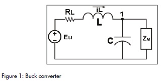
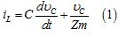
Applying Kirchhoff's current law at the node labelled 1 in Figure 1, the following equation (1) was obtained:
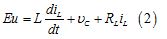
Applying Kirchhoff's voltage law on the mesh consisting of capacitor C, inductance L, resistance RL and the Eu source, equation (2) was obtained:
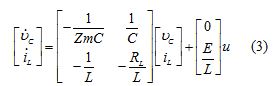
Taking the voltage on the capacitor and the current flowing through the inductance as state variables, it is the representation in state space from equations (1) and (2) as shown by equation (3).
Summary:
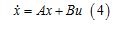
Control signal u took two values +1 and -1; there would then be two different topologies in each sampling period.
Simulink model
The model system was developed in Simulink, based on Hoyos'work (2009). Differential equations describing the converter dynamics and piecewise smooth dynamics associated with the topology variation were used.
Description of the assembly
The system consisted of the control receiving two signals: the reference signal and a signal providing information about buck converter (Vc) operation. Figure 7 depicts the control feedback loop. As mentioned previously, the control system was implemented by means of a DSP board featuring the following advantages: fast response, easy programming and versatility (Hoyos, Huertas et al., 2009).
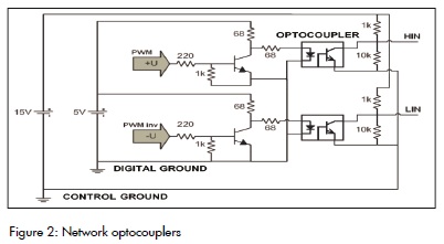
Figure 2 shows the control which transferred the value of the output to a network of optocouplers for security purposes. The aim was to protect the board and to isolate the components associated with both control and power. The optocouplers then transferred their signal to the drivers serving to polarise the Mosfet power transistors. The drivers also transferred the signal to the inverter bridge.
The inverter is a mechanism providing voltage values to the buck converter, either +E or -E. These values are computed by the control. The buck converter can be viewed as a filter smoothing the signal from the inverter and minimising switching ripple.
The converter transmitted its regulated voltage to the permanent magnet DC motor, thereby controlling its speed by varying armature voltage (V_motor).
Buck converter output voltage controlled feedback; this signal had to be conditioned so that it could be read by the DSP board because, if its operating ranges were exceeded, then damage could have ensued. Consequently, all the instrumentation required for acquiring the signal had to be done. This is described in detail for the various blocks of the flowchart.
Optocoupler protection
Since the output obtained with DSP was referenced to the PC, the digital part of the power had to be decoupled. A network with a J312 optocoupler was used to do so, as shown in Figure 2.
The operation of this circuit used a DS1104 card providing digital output for its two PWM signals responsible for the control action to be executed in real time; these signals polarised the scheme using 2N2222 transistors. When transistors are fed at high voltage level (5V) they enter a state of saturation, which means that current must be driven through them. This causes the current to deviate from the source to the ground without passing through the optocoupler.
Networks that deny transistors behave in a logical way so that input levels are high, output levels are low, and vice versa. Optocoupler outputs have high and low logic levels given by 13.6V and 0V voltage, respectively.
Drivers
After isolating the digital power devices, the next step was to run the IR2110 driver. The driver conditioning the signal to be finally delivered to the half-bridge switching elements were MOSFET power transistors. The IR2110 was suitable for this application requiring a fast speed control switch and was also able to isolate the two signals from the optocouplers so that they could switch the power transistors.
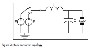
Buck-boost
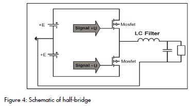
The middle bridge, or buck-boost, is the hardware that lets one change power polarity according to a control signal. Figure 3 shows a buck converter that would change supply polarity. In this type of half-bridge structure, the structure differs from conventional buck and this situation prevents the inductor from current going to zero at some point, so there is no discontinuous conduction mode. Hoyos(Hoyos, 2009; Angulo, Hoyos et al., 2008) proposed a way to bridge this task. This topology was also used in our case with N channel Mosfet power transistors, as shown in Figure 4
Buck converter
Figure 5 shows the model used, which was an LC filter. The modulated signal was obtained at this stage which is the signal that the user wants to use to output to its load. As known, the filter will arrive carrying signals in high-frequency PWM format and regulated AC and DC can be obtained output thanks to the LC combination.
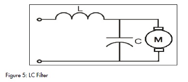
The half-bridge was used to feed the buck converter with + E and -E voltages. In positive polarity, the rate of change of current was positive and the other polarity was negative. The converter output voltage was the same voltage delivered to the capacitor and the DC motor, as shown in Figure 5.
Sensing and signal conditioning
The signals were prepared as shown in Figure 6. It can be seen that the voltage was sensing a resistive sensor which was used with large value resistors to avoid disturbing the real signal and the current was used with a value of 1 Ohm resistor to read its voltage drop.
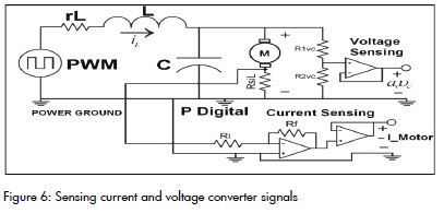
The signal was properly adjusted using the method described by Hoyos (Hoyos, Cano et al., 2009; Hoyos, Younes et al., 2010) to suppress noise present due to switching.
The current signal was also amplified by a factor given by equation 5, since it was very small. The voltage and current signals were carried to the inputs ADCHx board by shielded cable.

Controller
Control was implemented with dSPACE DS1104 card; the card improved the PC for developing systems for rapid control prototyping. Their input and output interfaces made this card ideal for developing varied control.
The board was internally divided into functional blocks that made it useful for control and real-time processing. The card had analog-digital converters and digital-analog to facilitate communication with the outside, which also allowed real time data acquisition. Such internal converters facilitated the task of implementing the circuit, as it was not necessary to implement this phase. Care had to be taken to never exceed the card's maximum permitted voltage terminal input.
Figure 7 shows the block diagram algorithm implemented in real time on the DSP.
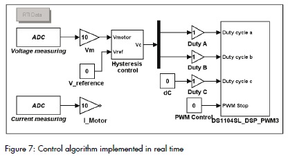
The first step consisted of acquiring the state variables, which were capacitor voltage (motor voltage Vc) and motor current. These signals were processed in this same stage to match the measurement units; they fit well so that the signals could be displayed in graphs. After validating the entries, the control action was calculated with zero hysteresis. This required having information about the state of the output of the plant being controlled and the reference selected by the user.
Hysteresis control
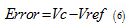
Controllers based on hysteresis have the advantage of being simple and overly fast. This kind of control was used: equation (6) was used to implement it. Its performance was adequate for simple systems admitting small oscillations. It is important to have small switching frequency of electromechanical components in hysteresis control. The aim was to prevent deterioration and extend these components' life.
Results
The permanent magnet motor data used in the experiment was: 250W rated power, 42VDC rated voltage, 6ADC rated current, 4,000 rpm max speed, 0.6 Ohms resistance. The LC filter values were 2.076mH and 28.56 uF.
The permanent magnet DC motor speed was directly proportional to the armature's applied voltage, as is shown in equations (6) and (7). Therein, the denominator parameters were constant because they depended on motor building characteristics and external excitation flow, which depended on the permanent magnets. Figure 8 shows the experimental results for the motor with the zero hysteresis controller, which used equation (6). The speed was -2,000rpm when -20V voltage was supplied to the motor, whereas the speed was 2,500rpm when voltage was 20V. The transient behaviour of the current was:
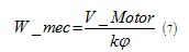
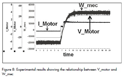
Figure 9 shows that output voltage value was varied instantaneously from 5V to 10V, and the current response was measured. The noise in the current was in the first section of the curve. The main cause for this noise was noise in the EMI hardware associated with transistor switching and measurement errors.
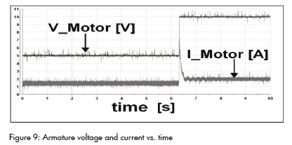
Figure 10 shows that instantaneous changes of 2V were incorporated in the voltage which was kept in the -10V to 10V interval.
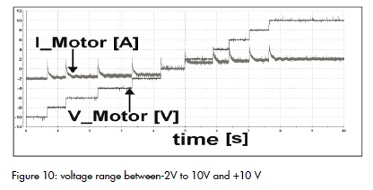
Figure 11 shows a more abrupt variation of voltage, from -10V to 10V. Therefore, the current peak was much more pronounced to the point of producing saturation in components that could not meet the system's current demand. This saturation could be noticed in the Figure as current peak truncation. As time elapses, the current value became quickly dampened until achieving a stable value which was proportional to voltage. This took around one second.
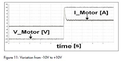
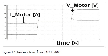
Figure 12 shows the abrupt changes in input voltage which remained close to input voltage limits. The Figure revealed that the voltage response took longer to achieve the 30V reference value. Saturation in the current should also be noted. At the end, both voltage and current signals achieved a steady value. The effects due to noise were less noticeable due to higher signal magnitude.
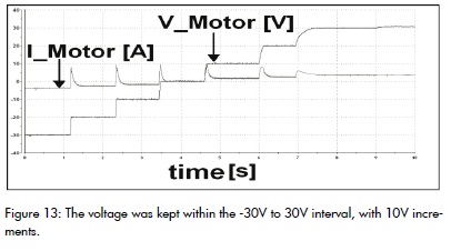
10V changes in voltage were incorporated which remained inside the -30 to 30V interval. The behaviour was not different regarding that of previous experiments, except at the end, when voltage and current signals were not regulated
Conclusions
The hysteresis system with DC motor control implemented in the DSP board had good performance.
An important application of RCP methodology was made for developing rapid control prototypes. The RCP controller results showed their efficiency.
The development tools used (dSPACE and Matlab) led to implementing real-time simulations. This represented a significant improvement over traditional simulation and the simulation interacted with the physical plant.
Working on blocks in Simulink model made it easy to make changes and improvements to the process control system design. This showed that development could be achieved in much less time than with usual methods in which these changes have led to changes in programmes and tours (with the complications that this entails). It was thus evident that development costs can be reduced.
Acknowledgements
We would like to thank the Manizales Research Department (DIMA), Universidad Nacional de Colombia and COLCIENCIAS' young researchers and innovators programme for their financial support
Angulo, F., Análisis de la dínámica de convertidores electrónicos de potencia usando PWM basado en promediado cero de la dinámica del error (ZAD)., Tesis Doctoral, Universidad Politécnica de Cataluña, España., Mayo 2004. [ Links ]
Angulo, F., Hoyos, F., Taborda, J., Hoyos, F., Olivart, G., Nonsmooth dynamics and FPIC chaos control in a dc-dc ZAD-strategy power converter., ENOC-2008, Vol. 55, pp:2392-2401., Saint Petersburg, Russia., 2008. [ Links ]
Dspace., ControlDesk experiment guide for ControlDesk 3.3 release 6.3., November 2008. [ Links ]
Hoyos, F., Desarrollo de software y hardware para manejo de un convertidor dc-dc y dc-ac controlado con ZAD y FPIC. Tesis de Maestría., Universidad Nacional de Colombia - Sede Manizales., Colombia., Julio 2009. [ Links ]
Hoyos, F., Cano, E., Younes, C., Reducción de IEM en convertidores Electrónicos de potencia., V Simposio Internacional sobre Calidad de la Energía Eléctrica SICEL 2009, Bogotá, Colombia 2009. [ Links ]
Hoyos, F., Huertas, D., Hoyos, A., Convertidor buck buck-boost controladodigitalmente con histeresis cero medianteun DSP., Aplicaciones Industriales., Revista Energética, Vol XXX, pp: 20-25., La Habana Cuba. 2009. [ Links ]
Hoyos, F, Taborda, J, Hoyos, C, Gonzales, E., Diseño e Implementación de un Inversor Monofásico Usando una Topología Buck., IV Simposio Internacional Sobre Calidad de La Energía Eléctrica., Manizales Colombia., 2007. [ Links ]
Hoyos, F., Younes, C., Cano, E., Técnicas de filtrado de IEM en convertidores electrónicos de potencia., Ingeniería e Investigación Vol. 30, No. 2, Agosto 2010, pp. 168-177. [ Links ]
Mathworks., Simulink, User's guide., 2010. [ Links ]
Mathworks., Real Time Workshop for use with Simulink, User's guide., (2010). [ Links ]
Rossi, P., Cano, E., Bruno. M., Godfrid, C., Desarrollo de un controlador de velocidad de un motor de inducción utilizando técnicas de realización rápida de prototipos., XIX Congreso Argentino de Control Automático, AADECA., 2004. [ Links ]

