


Servicios Personalizados
Revista
Articulo
 texto en
  Español (pdf)
 Articulo en XML
 Referencias del artículo
 Enviar articulo por email
Indicadores
-
 Citado por SciELO
 -
 Accesos
Links relacionados
-
 Citado por Google
 -
 Similares en
SciELO
Similares en
SciELO -
 Similares en Google
Compartir

 Permalink
Ingeniería e Investigación
versión impresa ISSN 0120-5609
Ing. Investig. v.31 n.3 Bogotá sep./dic. 2011
Technical-parameter calculation model for underground lowpower electrical lines and indoor installations used in telecommunications
Henry Bastidas Mora1, Marlon Patiño Bernal2, Gilma Inés Ángel Castillo3
1 Electrical Engineer, Universidad Nacional de Colombia, Specialist in transmission systems and subtrasmisión, Universidad de los Andes, Masters in Telecommunications Engineering , Universidad Nacional de Colombia.. Current affila-tion: Universidad Piloto de Colombia. henry-bastidas@unipiloto.edu.co
2 Electronic Engineer, Specialist in Mobile Telecommunications, Universidad Distrital Francisco José de Caldas, Masters in Telecommunications Engineering, Universidad Nacional de Colombia. Current Affiliation: Universidad Distrital Francisco José de Caldas. marlonpb@udistrital.edu.co
3 Electronic Engineer, Specialist in Tele-Information, Universidad Distrital Francisco José de Caldas, Master in Electronics and Computer Engineering, Universidad de los Andes. Current Affiliation: Universidad de San Buenaventura. gangel@usbbog.edu.co
ABSTRACT
This article presents an analysis of electrical distribution theory for 60Hz-lines operating at low voltage, particularly underground lines and residential indoor installations. Such distribution lines' behaviour is observed as a function of frequency to consider any advantages regarding the potential use of power transmission lines (PTL) for transmitting telecommunication signals. A method for computing the secondary parameters is proposed which has been based on the primary parameters, namely inductance, capacitance, conductance and resistance. The secondary parameters so obtained were characteristic impedance, propagation constant (together with its real value) and the attenuation constant. Conductor configurations, insulation materials and gauges commonly used in Colombia were verified for such low-voltage lines. A mathematical model is proposed as a theoretical tool for analysing and predicting characteristic impedance pattern and the attenuations which occur at high frequencies, thereby complementing our group's previous work. Conclusions are drawn, together with a perspective regarding future work and applications.
Keywords: PLT, BPL, inductance, capacitance, leakage conductance, resistance, characteristic impedance, propagation constant, attenuation.
Received: July 30th 2010 Accepted: November 13th 2011
Introduction
Power line telecommunication technology (PLT), also known as power line communication (PLC), more recently coined broadband power line (BPL), makes it possible to transmit telecommunication signals through the electrical grid, turning high voltage wiring into communication channels.
Low-power transmission lines' ubiquity offers great potential in terms of future achievements by using PLC/BPL technology to offer telecommunication services in urban and rural areas. This technology has been implemented in Europe, North America and some South American countries like Chile and Brazil and, until recently, Ecuador. PLT has been analysed in Colombia from an academic standpoint (Malaver, Moreno and Ramos, 2002; Cruz, Gijón and Ramos, 2005; Bastidas, 2005), and so the Colombian government, whose policies currently attempt to promote the widespread use of broadband services (official scheme called "Promoción y masificación de la banda ancha en Colombia", Ministerio de Comunicaciones and CRT, Version II, 2005), has recognised the importance of PLT as an alternative for facilitating telecommunication access around the country.
Because the electrical grid was not designed to provide telecommunication-associated services, its conventional operation creates a whole range of noise types, attenuations, coupling difficulties, etc. (Dostert, 2000; Zimmermann and Dostert, 2002; Ka-pareliotis and Drakakis 2008), which makes electrical power networks an interesting challenge in terms of technology allowing the use of power transmission lines (PTL) as a communication channel. It is expected that different PLT systems will be implemented according to specific conditions since electrical power networks have different configurations, namely overhead lines and underground lines handling different voltage levels distributed both outdoors and indoors (for residential and commercial use).
An electrical transmission line involves four parameters (known as primary parameters) affecting its ability to fulfil the requirements of its functions as part of a whole power system: resistance, inductance, capacitance and conductance. These parameters are essential in determining the properties of a particular PLT channel which will be used for transmitting telecommunication signals. Resistance levels rise significantly as frequency increases; on the contrary, inductance and capacitance levels are not so dependent on frequency. In addition to resistance, inductance, capacitance and conductance another two parameters are associated with transmission lines called secondary parameters, namely characteristic impedance ZLand propagation constant g. Both these parameters are represented by complex numbers and are also a function of frequency (f) and the primary parameters.
Secondary parameters are not frequently used when dealing with power transmission lines since their very formulation is based on transmission lines for telecommunications (Neri, 2007)
A transmission line's characteristic impedance can be calculated as follows:
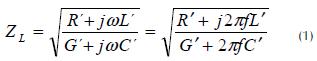
and the propagation constant is expressed by the following equation:
where R´ represents resistance per unit length, G´ is the leakage conductance per unit length, L´ represents inductance per unit length and C´ is capacitance per unit length. ω = ∏f: ω = angular velocity and f is the frequency. The values corresponding to a and b are called attenuation constant and phase constant respectively. Attenuation constant a units of measurement are nepers4 per unit length and the units are on radians per unit length in the case of the phase constant b .
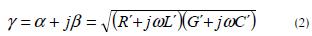
Transmission lines intended for distributing electrical power with minimum losses can normally be calculated in a simple fashion by using expressions for low-loss transmission lines as follows:
Low-voltage levels
Low-voltage networks (LV) normally use 110 to 440 volts, although different voltages may occasionally be found.5 The impedance of an electrical power line operating at low voltage is strongly connected to the current demanded by a particular load. Impedance will never be constant because a load is constantly varying due to different types of electrical equipment being plugged in and also unplugged all the time. When impedance changes, there is a slight variation in voltage; such impedance variation (caused by load variations) means that filters must be used which respond to fluctuations, representing an evident issue which does not affect "normal" telecommunication channels. LV networks can be either overhead or underground: overhead lines can be built using either bare conductors or insulated conductors; lines are insulated for underground networks.
Underground low-voltage (LV) transmission lines' behaviour
Many insulated conductors are used in LV distribution networks, having all sorts of mechanical and electrical characteristics. This means that the parameters of interest for the present study, specifically in terms of attenuation and characteristic impedance, exhibit a high degree of dispersion. One of the main cable topologies used in many countries (and also in Colombia) has been identified in the present article. Such topology is represented by a cable configuration that uses a three-insulated-phase structure surrounded by the neutral conductor.
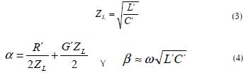
Three-phase-conductor configuration with external concentric neutral
This configuration consists of three individually-insulated circular conductors surrounded by a neutral cable. Figure 1 shows a magnetic-field representation (to analyse magnetic fields' layout and shape) that includes the aforementioned phases L1, L2 and L3, while the external conductor works as ground-neutral protection.
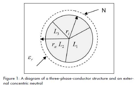
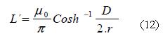
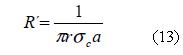
When using symmetric power supply, the difference in voltage between each phase and the neutral equals zero. The difference in voltage between phase conductors along a transmission line remains unchanged due to the symmetrical array and the symmetric terminals; consequently, the gap between conductors is a free area, and there is also electrical radial field formation towards the external conductor. This means that the electric field is radial-orientated between conductors, resembling a coaxial cable operating at high frequency. A small gap between conductors is assumed in comparison with radii ra and ri. It was thus proposed calculating both capacitance per unit length, C', and inductance per unit length, L', by using the expressions associated with coaxial cables, as follows:
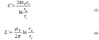
In (5) and (6), ra was the exterior conductor's internal radius and ri was the phase conductors' radius, eo represented the air's dielectric constant, mo represented free space permeability and er was the relative dielectric constant.
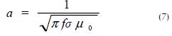
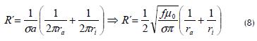
The resistance per unit length R' at high frequency was essentially determined by the skin effect since current only flows over a relatively thin layer on the conductor's external surface. Penetration depth a depended on frequency f and also on the wire's specific conductivity σ; this was calculated as follows:
According to coaxial cable theory, resistance per unit length can be calculated as follows:
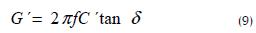
The losses in conductance per unit length G 'of a line can be calculated if the losses are multiplied capacitance by a factor as δ
It is known that R '<< wL' for high frequencies because R 'increases proportionally with the square root of the frequency f. Additionally, if the loss factor tan d is δ << 1 for insulating materials most often used such as PVC, and for high frequencies, it is also possible to assume G '<< wC'. This means that a typical underground cable can be modeled as low losses. The characteristic impedance Z, the attenuation constant α and the phase constant β can be estimated appropriately with equations (3) and (4). The attenuation L (f, l) can be calculated from the factor attenuation α(f) depending on the length l in dB

It should be stated that dielectric constant er, also depended on frequency but its variations were not so relevant since, when applied using a logarithmic scale on the frequency axis, the graph yielded a curve whose value was er ≈ 3.8 (at 1 MHz), with er ≈ 2.9 reduction (at 20 Mhz). Loss due to the PVC's tand factor gave a 0.05 at 1MHz linear approximation on the logarithmic -scale axis, gradually decreasing down to about 0.01 at 20 MHz.
Calculations were performed using the aforementioned equations to determine both characteristic impedance and attenuation as a function of frequency. The conductor used as an example of the calculations had a ri1 cm6 internal radius. The ratio ra/ riwas 1.2 and PVC insulation was also considered.
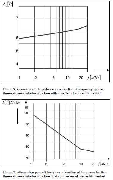
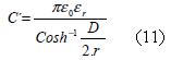
Figures 2 and 3 show the resulting curves for characteristic impedance ZLand attenuation L (f) for length l = 1 km and for a 1 and 20 MHz frequency range.
It is worth noting that the characteristic impedance ZL, for this specific layout and conductor gauge remained in the 5.6 - 6.4W range. This confirmed the assumption that the medium itself causes low losses and also that characteristic impedance does not exhibit significant fluctuations associated with frequency changes. As expected, attenuation L(f) rose as frequency increased, having calculated values of 16.4 dB at 1 MHz, up to 60.5 dB at 20 MHz.
Indoor installation wiring
The design of residential electric installations in Colombia complies with the NTC 2050 standard; 6, 8, 10, 12 and 14 AWG wire gauge are used The most common wire gauge found in typical electrical outlets (that would be used for PLT) is 14 AWG, which is used for phases as well as for the neutral. This wire gauge is normally installed throughout a half an inch (½ in) diameter PVC pipeline. Such wiring configuration certainly corresponds to a traditional bifilar line. In this particular case, taking into account that the gap between cables is less than 10 times the radius of the conductors, and for the sake of precision, cosh equations would be applied instead of using those involving ln, (Vela, 2007) then:
By substituting the penetration depth, a, found in (7) in (16), and considering that copper is the most common conductor for indoor installations, whose conductivity value is  then:
then:
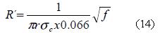
Using these expressions for a 14-AWG gauge conductor, corresponding to a 0.8-mm radius, and also assuming distance D = (1.25x 2r), together with (3) and (4), the calculated values summarised in Figures 4 and 5 were obtained:
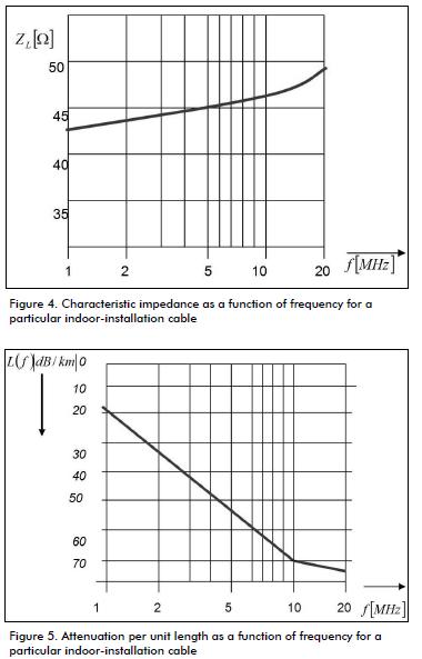
It is worth mentioning that characteristic impedance values were slightly higher than those obtained when using the other two prior wiring configurations; the values so calculated were 42.64 W at 1MHz and 48.88 W at 20 MHz. The results for attenuation per unit length were 19.45 dB/km at 1 MHz and 72.34 dB/km at 20 MHz.
Conclusions
The properties of the most common transmission lines used in underground power distribution networks have been studied (considering indoor and outdoor use as well as low and high frequency up to 20 MHz). The present study has shown that cable-associated attenuation is essentially determined by the properties of the dielectric materials employed. A whole range of materials are used for insulation, thereby hampering precise generalisation. This article has been focused on studying PVC insulation which is probably one of the most widely-used materials for which data is readily available. It has been shown that attenuation did not reach critical values at frequencies up to 20 MHz over a 1-Km length line, suggesting that such distribution networks might be used for transmitting telecommunication signals without running into considerable difficulties. These concluding remarks, together with the ubiquity of electrical power lines, clearly show the great potential for PLT development in Colombia, as already seen in other countries.
The theoretical basis presented in this article for underground wiring and indoor installations applies to most existing conductor layouts (whether urban or rural) operating at low-voltage within the aforementioned frequency range.
Future work should attempt to take accurate measurements allowing comparison with the results in this study, and also contribute towards keeping a record of the various types of existing wiring at different locations which, for example, may help to determine the effects of using insulating materials different to PVC.
Likewise, it seems plausible that pilot tests should be conducted on up-to-date telecommunication signal transmissions over the electrical distribution lines available. All these tests should be carried out within the frequency range suggested here to implement technologies like ADSL, for example.
FOOTNOTES
4Un neper es igual a 8,686 decibelios.
5Según el Reglamento Técnico de Instalaciones Eléctricas (Retie), son consideradas redes de bajo voltaje aquellas entre 25 y 1.000 voltios.
6Los calibres de conductores utilizados en Colombia para redes subterráneas de baja tensión están entre 1 AWG y 500 MCM, correspondiendo 1 cm a un radio intermedio entre ellos.
References
Alexander, C., Sadiku, M., Fundamentos de Circuitos Eléctricos., Mc Graw Hill editores, México, D.F., 2006.
Amirshahi, P., Navidpour, S., Kavehrad, M., Performance Analysis of OFDM Broadband Communications System Over Low Voltage Powerline with Impulsive Noise., IEEE ICC 2006 proceedings.
Anatory, J., Theethayi, N., Kissaka, M., Mvungi, N., Broadband Power Line Communications: Performance Analysis., International Journal of Applied Science, Engineering and Technology 3;3 © www.waset.org Summer 2007
Banwell, T., Galli, S., A Novel Approach to Accurate Modeling of the Indoor Power Line Channel. Part I: Fundamental Analysis and Circuit Models, and Part II: Transfer Function and Channel Properties., Submitted IEEE Trans. Commun., Jan. 2003.
Bastidas, H., Modelando algunas características de las redes eléctricas usadas como canal para proveer telecomunicaciones., Ingeniería e Investigación, Vol. 25, No. 3, diciembre de 2005, pp.111-115.
Bastidas, H., Fundamentos teóricos para el cálculo de los parámetros técnicos de las líneas eléctricas aéreas de baja tensión para su uso en telecomunicaciones., Ingeniería e Investigación, Vol. 29 No. 2, agosto de 2009, pp. 107-111.
Cañete, F., Broadband Modeling of Indoor Power-line Channels., IEEE Trans. Consumer Elect. Vol. 48, no.1, Feb. 2002.
Cruz, J., Gijón, C., Ramos, Z., Determinación Experimental de la Impedancia Presente en una Instalación de Baja Tensión., GITUN, Bogotá D.C., 2005
Carlson, A.B., Sistemas de Comunicación. Mc Graw Hill. 3ªEdición. 2003.
Couch II, León W., Sistemas de Comunicaciones Digitales y Analógicos. Prentice Hall, Quinta Edición, México, 2004.
Dorf, S., Circuitos Eléctricos Introducción al Análisis y Diseño., Alfaomega editores. 5ª Edición, México, D.F., 2007
Dostert, K., Zimmermann, M., Waldeck, T., Arzberger, M., Fundamental properties of the low voltage power distribution grid used as a data channel., European Transactions on Telecommunications (ETT), Vol. 11, No. 3, May/June 2000.
Dostert, K., Telecommunications over the power distribution grid-possibilities and limitations., Proceedings of the 1997 International Symposium on Power Line communications and Its Applications, Essen, Germany, April 1997.
García-Hernández, J., A Survey on BPL Communications Standards., IJCSNS International Journal of Computer Science and Network Security, Vol. 8 No. 10, October 2008
Hensen, C., Schulz, W., Time dependency of the channel characteristics of low voltage power-lines and its effects on hardware implementation., Int. Journal of Electronics and Communications (AEU), 54, No. 1, 2000.
IEEE P1901 Draft Standard for Broadband over Power Line Networks: Medium Access Control and Physical Layer Specifications., February 2006
Instituto Colombiano De Energía Eléctrica - ICEL., Normas para el diseño y construcción de sistemas de subtransmisión y distribución, Volumen IV -1998
Instituto Colombiano De Normas Técnicas Y Certificación ICONTEC., Reglamento Técnico de Instalaciones Eléctricas-RETIE, 2007
Kapareliotis, E., Drakakis, K., Dimitriades, H., Capsalis, C., Throughput Analysis on BPL Networks., Microwave Review, September 2008.
Malaver, H., Moreno, A., Ramos Z., Análisis y Diseño del Modelo de Interconexión de una Red de Telecomunicaciones que Presta el Servicio de Valor Agregado Internet con una Red Eléctrica Tradicional en Colombia., GITUN, Bogotá D.C, 2002.
Misurec, J., Interference in data communication over narrowband PLC., IJCSNS International Journal of Computer Science and Network Security, VOL.8 No.11, November 2008.
Neri, V., Líneas de Transmisión., McGRAW-HILL editores. 5ª Edición, México, D.F., 2007.
Tsakiris, S., Salis, A., Uzunoglu, N., Performance of OFDM Systems for Broadband Power Line Communications Under Low Signal Strength., Microwave Review December, 2009.
Zimmermann, M., Dostert, K., A Mutipath Model for the Power line Channel., IEEE Trans. Commun, vol. 50, no. 4, Apr. 2002, pp.553-59.
Zimmermann, M., Dostert, K., Analysis and Modeling of Impulsive Noise in Broadband Powerline Communications. IEEE Trans., Electromagnetic Compatibility, vol. 44, 1, Feb. 2002, pp. 249-58.
Alexander, C., Sadiku, M., Fundamentos de Circuitos Eléctricos., Mc Graw Hill editores, México, D.F., 2006. [ Links ]
Amirshahi, P., Navidpour, S., Kavehrad, M., Performance Analysis of OFDM Broadband Communications System Over Low Voltage Powerline with Impulsive Noise., IEEE ICC 2006 proceedings. [ Links ]
Anatory, J., Theethayi, N., Kissaka, M., Mvungi, N., Broadband Power Line Communications: Performance Analysis., International Journal of Applied Science, Engineering and Technology 3;3 © www.waset.org Summer 2007 [ Links ]
Banwell, T., Galli, S., A Novel Approach to Accurate Modeling of the Indoor Power Line Channel. Part I: Fundamental Analysis and Circuit Models, and Part II: Transfer Function and Channel Properties., Submitted IEEE Trans. Commun., Jan. 2003. [ Links ]
Bastidas, H., Modelando algunas características de las redes eléctricas usadas como canal para proveer telecomunicaciones., Ingeniería e Investigación, Vol. 25, No. 3, diciembre de 2005, pp.111-115. [ Links ]
Bastidas, H., Fundamentos teóricos para el cálculo de los parámetros técnicos de las líneas eléctricas aéreas de baja tensión para su uso en telecomunicaciones., Ingeniería e Investigación, Vol. 29 No. 2, agosto de 2009, pp. 107-111. [ Links ]
Cañete, F., Broadband Modeling of Indoor Power-line Channels., IEEE Trans. Consumer Elect. Vol. 48, no.1, Feb. 2002. [ Links ]
Cruz, J., Gijón, C., Ramos, Z., Determinación Experimental de la Impedancia Presente en una Instalación de Baja Tensión., GITUN, Bogotá D.C., 2005 [ Links ]
Carlson, A.B., Sistemas de Comunicación. Mc Graw Hill. 3ªEdición. 2003. [ Links ]
Couch II, León W., Sistemas de Comunicaciones Digitales y Analógicos. Prentice Hall, Quinta Edición, México, 2004. [ Links ]
Dorf, S., Circuitos Eléctricos Introducción al Análisis y Diseño., Alfaomega editores. 5ª Edición, México, D.F., 2007 [ Links ]
Dostert, K., Zimmermann, M., Waldeck, T., Arzberger, M., Fundamental properties of the low voltage power distribution grid used as a data channel., European Transactions on Telecommunications (ETT), Vol. 11, No. 3, May/June 2000. [ Links ]
Dostert, K., Telecommunications over the power distribution grid-possibilities and limitations., Proceedings of the 1997 International Symposium on Power Line communications and Its Applications, Essen, Germany, April 1997. [ Links ]
García-Hernández, J., A Survey on BPL Communications Standards., IJCSNS International Journal of Computer Science and Network Security, Vol. 8 No. 10, October 2008 [ Links ]
Hensen, C., Schulz, W., Time dependency of the channel characteristics of low voltage power-lines and its effects on hardware implementation., Int. Journal of Electronics and Communications (AEU), 54, No. 1, 2000. [ Links ]
IEEE P1901 Draft Standard for Broadband over Power Line Networks: Medium Access Control and Physical Layer Specifications., February 2006 [ Links ]
Instituto Colombiano De Energía Eléctrica - ICEL., Normas para el diseño y construcción de sistemas de subtransmisión y distribución, Volumen IV -1998 [ Links ]
Instituto Colombiano De Normas Técnicas Y Certificación ICONTEC., Reglamento Técnico de Instalaciones Eléctricas-RETIE, 2007 [ Links ]
Kapareliotis, E., Drakakis, K., Dimitriades, H., Capsalis, C., Throughput Analysis on BPL Networks., Microwave Review, September 2008. [ Links ]
Malaver, H., Moreno, A., Ramos Z., Análisis y Diseño del Modelo de Interconexión de una Red de Telecomunicaciones que Presta el Servicio de Valor Agregado Internet con una Red Eléctrica Tradicional en Colombia., GITUN, Bogotá D.C, 2002. [ Links ]
Misurec, J., Interference in data communication over narrowband PLC., IJCSNS International Journal of Computer Science and Network Security, VOL.8 No.11, November 2008. [ Links ]
Neri, V., Líneas de Transmisión., McGRAW-HILL editores. 5ª Edición, México, D.F., 2007. [ Links ]
Tsakiris, S., Salis, A., Uzunoglu, N., Performance of OFDM Systems for Broadband Power Line Communications Under Low Signal Strength., Microwave Review December, 2009. [ Links ]
Zimmermann, M., Dostert, K., A Mutipath Model for the Power line Channel., IEEE Trans. Commun, vol. 50, no. 4, Apr. 2002, pp.553-59. [ Links ]
Zimmermann, M., Dostert, K., Analysis and Modeling of Impulsive Noise in Broadband Powerline Communications. IEEE Trans., Electromagnetic Compatibility, vol. 44, 1, Feb. 2002, pp. 249-58. [ Links ]

