


Services on Demand
Journal
Article
 English (pdf)
 Article in xml format
 Article references
 Send this article by e-mail
Indicators
-
 Cited by SciELO
 -
 Access statistics
Related links
-
 Cited by Google
 -
 Similars in
SciELO
Similars in
SciELO -
 Similars in Google
Share

 Permalink
Ingeniería e Investigación
Print version ISSN 0120-5609
Ing. Investig. vol.31 suppl.2 Bogotá Oct. 2011
Studying and simulating transformer configuration to improve power quality
Estudio y Simulación de las Configuraciones de Transformadores para el Mejoramiento de la Calidad de Energía
Oscar J. Peña Huaringa1
1 O. J. Peña Ingeniero electricista en la Universidad Nacional de Ingeniería LIMA- PERU. Estudiante de Maestría en Sistemas de Potencia de la Universidad Nacional de Ingeniería. UNI-MINEM CARELEC, Actualmente trabaja en SCHNEIDER ELECTRIC en la línea de negocio de Energy (email: oscarpenah@gmail.com)
ABSTRACT
This paper presents a study and simulation of transformer configurations to improve power quality; it provides theoretical support based on the expansion of the Fourier series and analysis of symmetrical components. A test system was set up in the laboratory, taking measurements and checking configuration effectiveness in reducing the system's harmonic content. The configurations were modelled with PSCAD / EMTDC software, using two 6 pulse rectifiers as test loads and two variable speed drives.Keywords: harmonics, power quality, symmetrical components, converters, transformers.
RESUMEN
Este artículo presenta el estudio y la simulación de las configuraciones de transformadores para el mejoramiento de la calidad de energía, mostrando el sustento teórico basado en la expansión de las series de fourier y el análisis de las componentes simétricas. Se implementa un sistema de prueba en el laboratorio, realizando mediciones y verificando la efectividad de las configuraciones en la reducción del contenido armónico del sistema. Las configuraciones son modeladas utilizando el software PSCAD/EMTDC empleando como cargas de prueba rectificadores de 6 pulsos, así como variadores de velocidad.Palabras claves: Armónicos, Calidad de Energía, Componentes Simétricas, Convertidores, Transformadores
1. Introduction
The effects of power system harmonics are varied, i.e. instantaneous (on measuring instruments and communication systems) and long-term effects (additional losses in machines and transformers, capacitor banks, wire heating and equipment, etc.). The consequences are many, for example, loss of equipment insulating capacity (shorter life time or total inoperability) or protection systems' inadequate performance (leading to important loads becoming disconnected and thus penalties).
There are different solutions for each specific problem regarding harmonic pollution in electrical systems, such as shock reactance, passive filters, anti-resonance inductances and other solutions involving power electronics, such as active and hybrid filters.
Using transformers allows a system's harmonic content to become reduced, especially where converters have been connected so that their harmonics are terminated by harmonics produced by other converters.
This paper analyses different transformer configurations allowing harmonic contamination to become reduced in a system caused by 3rd , 5th , 7th , 11th and 13th harmonics. A test system was set up in the laboratory and software was used to model configurations in PSCAD / EMTDC, considering nonlinear loads (rectifiers and variable speed drives).
The simulated systems assigned forces regarding harmonic modelling and simulation. (IEEE Trans, 1996a; IEEE Trans, 1996b).
2. Objective
- Showing and analysing transformer configurations letting them decrease the degree of harmonic pollution in a system; and
- Presenting the results of theoretical-experimental comparison (PSCAD / EMTDC laboratory - software).
3. Configuration of transformers for reducing third harmonic and ITS multiples
A. System Analysis
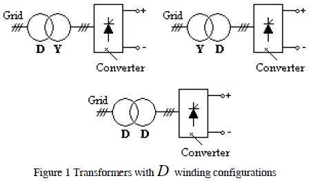
The most commonly used three-phase transformer configurations in power systems are D Y, Y D. Such configurations are shown in Figure 1 where a ratio of "a" between the primary and secondary transformer was assumed with 30° phase displacement between primary and secondary line currents which would be forward or backward depending on phase sequence (positive or negative).
These settings involved D. winding.
B. Harmonics and sequence components
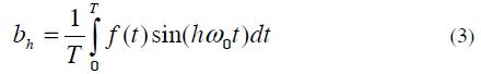
Fourier series represents an alternative for analysing current and voltage harmonic distortion when inter-harmonic and sub-harmonic components are not considered (Acevedo). A periodic waveform can be represented in Fourier series as
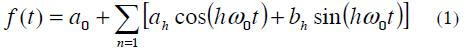
Where: ƒ (t) is a function of frecuency ƒ0, angular frequency ω0 =2πƒ0 and T period.
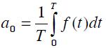 Is the average value of the function f (t)
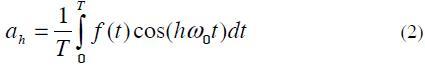
However, this expression can also be expressed as follows:
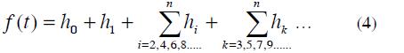
Where:
h0 : Continue component.
h1 : Fundamental components
hi : Pair harmonic components
hk : Odd harmonic components
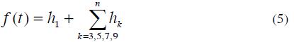
It was considered that the value of h0 equalled zero because this component was saturating the transformers.
Their pair harmonics were caused by arc furnaces, cycle converters, semi-controlled rectifiers (now obsolete due to their instability).
The odd harmonics were generated by computers based on static rectifiers and controlled rectifiers, mainly found in electrical systems.
To approach this system by simplifying expression (4)
We consider the currents:
Ia1 = I1 sin(ωt)
Ib1 = I1 sin(ωt -120° )
Ic1 = I1 sin(ωt - 240° )
Then for the 3th we have:
Ia3 = I3 sin(3ωt)
Ib3 = I3 sin(3ωt - 360) = I3 sin(3ωt)
Ic3 = I3 sin(3ωt - 720) = I3 sin(3ωt)
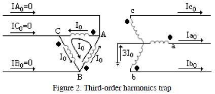
Then Ia3 = Ib3 = Ic3
Figure 2 shows how a D-Y connection trapped the third-order harmonics and its multiples in D , meaning that they did not circulate as harmonic components in primary line currents. If the winding in Y were not grounded, there would not be a neutral current and as zero sequence components were in phase there would be no possible path for these currents in the secondary line (Dugan and McGranaghan)
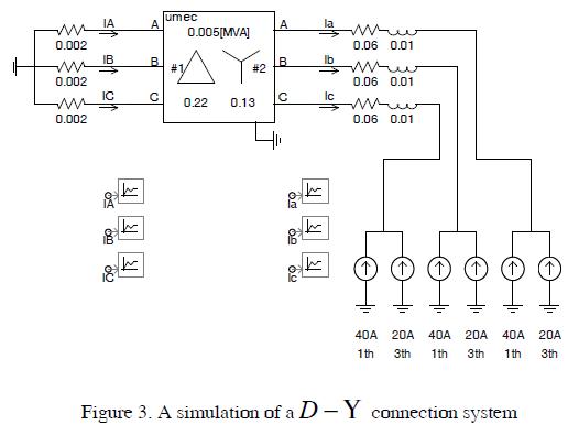
C. System Simulation
Figure 3 shows a system where the fundamental current was injected at 60Hz (40A) and 180Hz current (20A) to observe D winding performance as a trap for third-order harmonics.
The simulation results are shown in Figure 4. The current in the primary transformer ( IA) only contained fundamental components.
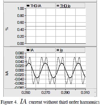
The THDi fell from 50% to 0%; it verified that third-order harmonics were trapped in the D winding.
4. Transformers configuration for reducing fifth and seventh harmonic
A. System Analysis
A transformer is a device which can change electrical signal phase angle, letting it minimise a system's harmonic content when two equal loads are connected in parallel through power transformers having different connections. This technique is very used in controlling harmonics generated by multipulse converters (Paice, 1995).
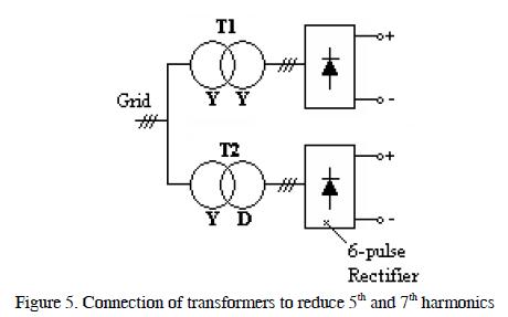
Figure 5 shows the configuration of a system for minimising 5th and 7th content in a system.
The T1 transformer had a U -U configuration; the 3rd component would evidently become trapped in the T2 transformer's D winding.
The T2 transformer entered a 30° phase displacement between primary side current and secondary side current, while primary and secondary currents were in phase in the T1 transformer.
If the 5th harmonic was from a negative sequence then it would produce a magnetic field in an engine rotating contrary to the fundamental component, thereby causing such engine to overheat and have lower than expected shaft speed.
If the 7th harmonic were from a positive sequence, then an engine would produce a magnetic field rotating in the same way as the fundamental component causing current to increase and greater than expected shaft speed.
B. Harmonic and sequence components
The equations for the sequence analysis of the 5th harmonic were as follows:
Ia5 = I5 sin(5ωt)Ib5 = I5 sin(5ωt - 600) = I5 sin(5ωt +120)
Ic5 = I5 sin(5wt -1200) = I5 sin(5wt -120)
Due to the -30° phase which the T2 transformer introduced, the 5th harmonic secondary currents had phase displacement at -30 * 5 =- 150°, regarding the T1 transformer.
As the 5ths behaved as negative sequence components then there was -30° phase displacement and therefore T2 primary currents had phase displacement at -150 - 30 =- 180° = 180°.
If T1 and T2 primary current magnitudes were equal, then the 5th would be cancelled and would not flow to the source.
The equations for sequence analysis of the 7th were as follows:
Ia7 = I7 sin(7ωt)Ib7 = I7 sin(7ωt -840) = I7 sin(7ωt -120)
Ic7 = I7 sin(7ωt -1680) = I7 sin(7ωt +120)
Due to the -30° phase displacement caused by introducing the T2 transformer, the secondary currents corresponding to the 5th harmonic had phase displacement at -30 * 7 =- 210° = 150°, regarding the T1 transformer. As the 7ths behaved as positive sequence components then there was -30° phase displacement and therefore T2 primary currents had 150 +30 = 180 phase displacement.
If T1 and T2 primary current magnitudes were equal, then the 7th would be cancelled and would not flow to the source.
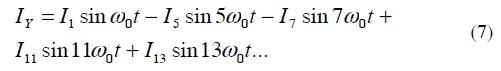
If six-pulse rectifiers were placed on the low voltage side of transformers T1 and T2, then the current on the low side would be given by: (Wakileh, 2011)
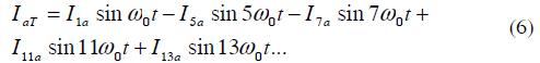
Then when this current is reflected in the high side of the Y-Y transformer we have:
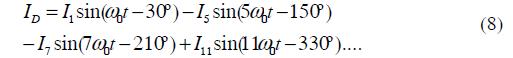
And in the D-Y transformer we have:
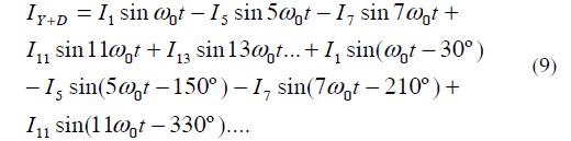
Then the total current in the high side will be IY + ID:

5. Using a zig zag transformer for reducing harmonic content
A. System Analysis
Phase shifting transformers are used to reduce multiple converters' harmonic currents.
The phase change should be appropriate for the number of converters. The phase shifting required for the minimum number of converters having 6 pulse waveforms would be:
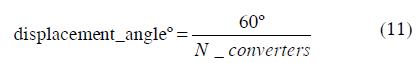
In multipulse circuits the individual harmonic currents of each converter bridge would be the same. Such arrangements allow the harmonic currents produced by a converter to be compensated by others.
The fact that the negative sequence voltages and currents were moving in the opposite course to the positive sequence values would also provide a mechanism for cancelling harmonics in pairs.
Zig-zag transformer connection types are primary in Y secondary in zig-zag ( Z ), primary in D and secondary in zig-zag ( Z ), both having positive Z+ and negative Z- phase displacement.
Figure 6 shows transformer array configuration for minimising the harmonic content of four 6-pulse rectifiers (i.e. 24 pulses).
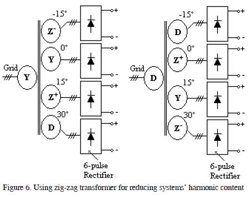
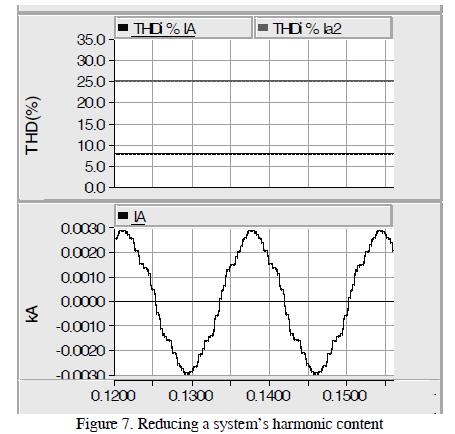
Figure 7 shows that the reduction in THDi system harmonic content of a converter was 25.5% and 8.2% for an equivalent system.
6. Implementing and simulating a harmonic filtering system for 5th and 7th harmonics using a transformer
A. System Description
Figure 8 shows the proper basic system connection diagram for testing a harmonic filtering system. The network had the following components:
- 220Vef supply voltage
- 2 5kVA transformers
- 3 network analysers with connection to a PC, internal data software
- 2 6-pulse power rectifiers/ 2 variable frequency speed drives
- 3 PCs
- Resistance, capacitance, inductance kits
- Connection wires.
Analysers B and C showed each transformer's individual spectral harmonics. Analyser A showed the array of both transformers' total contribution to the network.
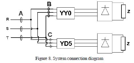
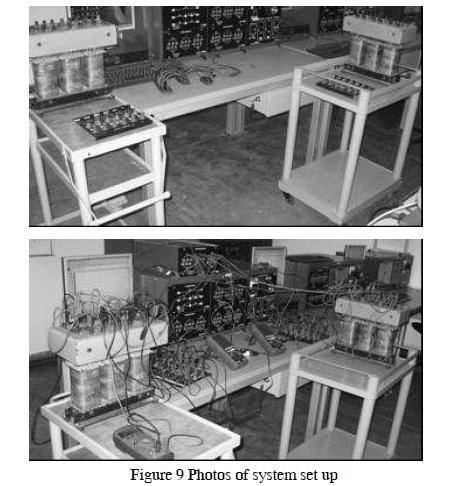
Figure 9 shows the system which was set up in the laboratory; this included measuring devices and PCs to observe the harmonic spectra, as well as necessary equipment.
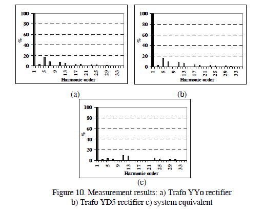
B. Results
Figure 10 shows the harmonic spectra obtained from the measurement equipment for each rectifier and source input.
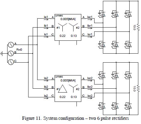
C. System Simulation
Figure 11 shows the system configuration.
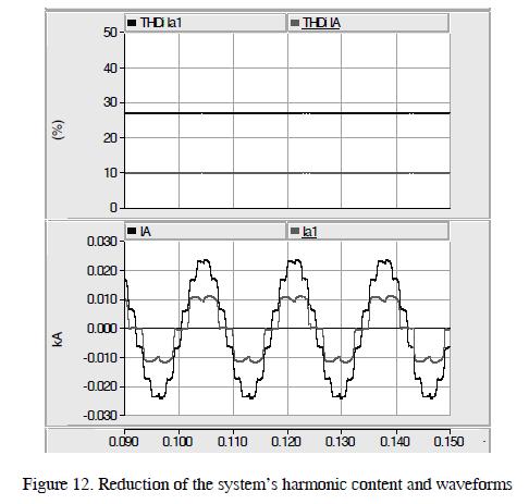
The results are shown in Figure 12 where it can be seen that THDi on the high side of the transformer was 27.45%, and THDi at the source was 10.25%. They confirmed harmonic content reduction in the system.
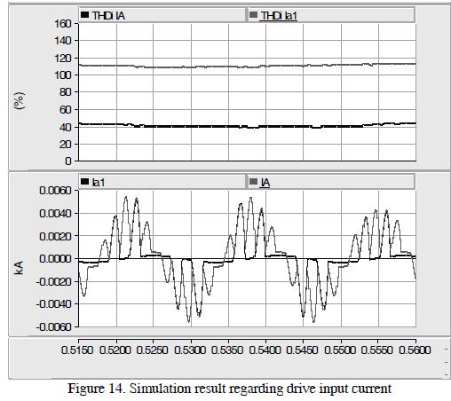
7. Application of the transformers array for variable speed drives
Figure 13 shows the system's configuration. Shaping the variable speed according to (Peña and Montes, 2007) it was considered here that the drives did not have choke reactance or mechanisms reducing the system's degree of contamination to appreciate the system's effectiveness.
Figure 14 shows that the THDi on high side of the transformer was 111.48%, and the THDi at the source was 41.15%. They confirmed reduction of the system's harmonic content.
8. Conclusions
- A transformer is a device which is able to shift an electric signal's phase angle, allowing a system's harmonics to become reduced when two equal loads were connected in parallel through power transformers having different phase shifts. Such transformer arrangements allowed one converter's harmonic currents to become compensated for by the other one.
- Third order harmonics and their multiples could be effectively filtered by using a D Y transformer. These harmonics appeared when 1-phase rectification loads were use at the main side, such as TVs, computers or lighting systems. This configuration could be used in buildings having wdimmable lighting systems.
- Using transformers in Y Y and D Y configurations could minimise a system's 5th and 7th harmonics. However, a lot of attention must be paid to the loads since they must have similar sizes since a difference in current amplitude would not allow efficiently filtering the harmonics in such system. This configuration could also be used to power loads having correct input, as shown in this paper (rectifiers and speed drives).
- When a larger number of converters' harmonics need to be filtered, zig-zag connection transformers should be used.
- Using these coupled transformer configurations in networks is recommended since, in many cases, it is more profitable than installing other filtering systems.
9. Acknowledgment
The author wishes to thank the Electrotechnical Laboratory at the Higher Technological Institute (TECSUP, Lima) for the support given me whilst carrying out this project.
10. References
Acevedo S. Conexión de Transformadores para Eliminar Armónicas. Departamento de Ingeniería Eléctrica. ITESM, Campus Monterrey. [ Links ]
Dugan, Roger C.; McGranaghan, Mark F.; Electrical Power System Quality [ Links ]
IEEE Transactions on Power Delivery Part I, Task Force on Harmonics Modeling and Simulation. Modeling and Simulation of the Propagation of Harmonics in Electric Power Networks. Part I: Concepts, Models, and Simulation Techniques. Vol. 11, N° 1, January 1996a, pp. 452-465. [ Links ]
IEEE Transactions on Power Delivery Part II, Task Force on Harmonics Modeling and Simulation. Modeling and Simulation of the Propagation of Harmonics in Electric Power Networks. Part II: Sample Systems and Examples, Vol. 11, N° 1, January 1996b, pp. 466-474. [ Links ]
Paice D, Power Electronics Converter Harmonics. Multipulse Methods for Clean Power. IEEE PRESS 1995. [ Links ]
Peña O and Montes F, Análisis de la Influencia armónica de los Variadores de velocidad en los Sistemas Eléctricos y Propuesta para Mitigar Armónicos. SICEL 2007 [ Links ]
Wakileh, George J. ''Power Systems Harmonics Fundamentals, Analysis and Filter Design'' Springer. 2001. [ Links ]

