


Services on Demand
Journal
Article
 English (pdf)
 Article in xml format
 Article references
 Send this article by e-mail
Indicators
-
 Cited by SciELO
 -
 Access statistics
Related links
-
 Cited by Google
 -
 Similars in
SciELO
Similars in
SciELO -
 Similars in Google
Share

 Permalink
Ingeniería e Investigación
Print version ISSN 0120-5609
Ing. Investig. vol.31 suppl.2 Bogotá Oct. 2011
Power Quality Problems Caused by Termites on 138-kV Underground Cables
Problemas de calidad de energía causados por termitas en cables subterráneos de 138kV
Romeu Fuscaldi1 , Fernando H. Silveira2 , Alberto De Conti3 , and Silvério Visacro4
1 Received the B.Sc. degree in electrical engineering from the Federal Center of Technological Education (CEFET), Belo Horizonte, Brazil, in 1984. He currently works as a senior engineer in the Power Utility of Minas Gerais (CEMIG). E-mail: fuscaldif@yahoo.com.br
2 Received the B.Sc., M.Sc., and Doctoral degrees in electrical engineering from the Federal University of Minas Gerais (UFMG), Belo Horizonte, Brazil, in 2000, 2001, and 2006, respectively. He is currently a Lecturer with the Department of Electrical Engineering, UFMG, and an Associate Researcher with the Lightning Research Center of the same institution. E-mail: silveira@cpdee.ufmg.br
3 Received the B.Sc., M.Sc., and Doctoral degrees in electrical engineering from the Federal University of Minas Gerais (UFMG), Belo Horizonte, Brazil, in 2000, 2001, and 2006, respectively. He is currently a Lecturer with the Department of Electrical Engineering, UFMG, and an Associate Researcher with the Lightning Research Center of the same institution. E-mail: conti@cpdee.ufmg.br
4 Received the B.Sc. and M.Sc. degrees in electrical engineering from the Federal University of Minas Gerais (UFMG), Belo Horizonte, in 1980 and 1984, respectively, and the Doctoral degree from the Federal University of Rio de Janeiro (UFRJ), Brazil, in 1992. Currently, he is a Full Professor of the Department of Electrical Engineering, UFMG, and the Head of the Lightning Research Center (LRC). E-mail: visacro@cpdee.ufmg.br
Abstract
This paper discusses problems found in the operation of underground cables in the transmission system of CEMIG, with emphasis on insulation failures caused by termites. This problem has been the source of many scheduled and non-scheduled interruptions in later years, leading to significant maintenance costs. Experience with current practices designed to detect and prevent this failure mode is described. It is argued that new procedures are needed for improved on-line, pre-failure detection. Test improvement will hopefully contribute to increase the lifetime of underground cables currently in use, as well as to reduce maintenance costs..Keywords: Transmission systems, termites, underground cables.
RESUMEN
Este artículo discute problemas encontrados en la operación de cables subterráneos en los sistemas de transmisión de CEMIG, con énfasis en las fallas de aislamiento causadas por las termitas. Problema que ha sido la fuente de muchas interrupciones programadas y no programadas en los últimos años, llevando a significantes costos de mantenimiento. Experiencias con las prácticas corrientes planeadas para detectar y prever este modo de falla esta descrito en este trabajo. Se establece que nuevos procedimientos son necesarios para mejorar durante el funcionamiento, la detección prefalla. La mejora de pruebas se espera que contribuya tanto a aumentar la vida útil de los cables subterráneos en operación, como a reducir los costos de mantenimiento.Palabras Claves: Sistemas de Transmisión, Termitas, Cables Subterráneos.
1. Introduction
In the seventies, three 138-kV underground cable systems were installed by CEMIG (Companhia Energética de Minas Gerais) in the center of Belo Horizonte, Brazil. The choice for an underground cable system was supported by advantages like (a) reliable energy supply with reduced number of outages, (b) no visual pollution, and (c) improved safety for personnel and population in general. Overall, the initial expectation of the utility was to obtain ''zero cost maintenance'', except against external agents (CEMIG's)
Such expectation was confirmed by the first generation of underground cables used in the transmission line system. Their design consisted of three metallic layers (core, sheath, and armor) insulated internally by oil-impregnated paper and externally by a PVC sheath. Core and sheath were copper-made, while the armor, which had the function of providing mechanical resistance to the cable, was made of lead.
The successful experience with the first generation of underground cables in the transmission system of Belo Horizonte has stimulated a system expansion in the eighties. At that time, however, a different cable design was used. It consisted of two metallic layers (core and sheath) insulated internally by oil-impregnated paper and externally by a PVC sheath. Cable core and sheath were made of aluminum and corrugated aluminum, respectively. Both the use of aluminum and the fact that only a pair of metallic layers were used in the new cable design contributed to let the cable lighter and easier to manipulate, especially in curves. Easier manipulation, lower production costs, and reduced installation costs indicated at that time that the new cable design would become a benchmark to the power supply to the center of big cities.
However, experience has shown that the performance of the new cable systems installed in the eighties, which are still in operation, is below expected because of problems with termites. This paper is intended to discuss this problem both in a technical and economical perspective (CEMIG's). The paper organization is as follows. Section II presents an overview of the transmission system in Belo Horizonte, with focus on underground cable systems. The cable design that has been victim of termite attacks is also presented in detail. Section III discusses operation problems caused by termites in underground cables, with focus on their technical and economical aspects. Section IV describes the test procedure currently in use to localize damages due to termites on underground cables. A discussion of the difficulties involved with this test is also presented. The paper is concluded in Section V with a discussion on future perspectives on the diagnosis of failures caused by termites in 138-kV underground cable systems.
2. 138-kv underground cable systems in Belo Horizonte
A. Overview
Fig. 1 illustrates the transmission system in the city of Belo Horizonte, Brazil. An external ring of 345-kV overhead lines connects the substations of Neves, Taquaril, and Barreiro. To obtain more flexibility, the transmission system is interconnected by transmission lines and substations, especially by 138-kV underground cables which are represented as dotted lines in Fig. 1. These underground cables have essentially two functions, namely (i) supplying the central area of the city with electrical energy, and (ii) allowing for the redistribution of power flux between the substations of Neves, Taquaril, and Barreiro whenever necessary (CEMIG's).
B. Type and characteristics of 138-kV underground cablesused in Belo Horizonte
All underground cables currently in use in the transmission system of Belo Horizonte are three-phase, single core, oilfilled cables. Differences are found in the number of conductors (core, sheath, and armor in the first generation of cables, core and sheath in the second generation of cables), and also in materials (copper and lead in the first generation of cables, aluminum and corrugated aluminum in the second generation of cables). Details of the cables connecting the substations shown in Fig. 1 are listed in Table I.
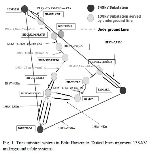
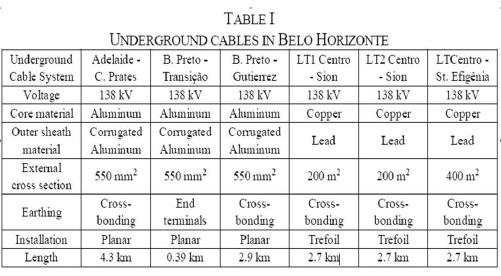
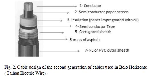
Fig. 2 illustrates the design of the second generation of cables used in the transmission system of Belo Horizonte. The core conductor is hollow and filled with oil. The main insulation consists of paper impregnated with oil. Semiconductor material is used both on the outer surface of the core conductor and on the inner surface of the sheath. The function of the semiconductor layers is to assure a uniform electric field distribution along the cable cross section, and to eliminate voltage gradients at certain points of the internal insulation (Rocha,200;Pirelli,1968). The inner insulation is covered by a corrugated aluminum sheath, which is protected from external agents by a PVC layer.
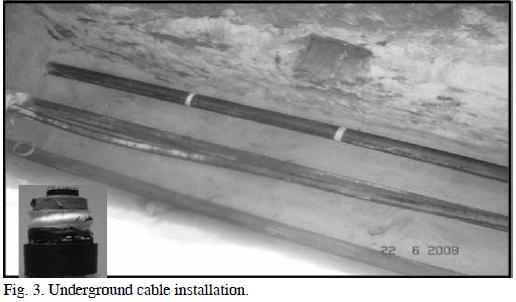
Fig. 3 illustrates the installation of a three-phase, single core underground cable system. The installation method consists of digging a trench and laying the cables directly in it. This solution is economically interesting because no heavy work is necessary besides digging and refilling the trench. This technique is used in both urban and rural areas.
Oil-filled underground cables present excellent electrical performance. However, higher operational costs and the risk of soil contamination due to oil leakage, which can be caused by termites, have been gradually leading utilities to use extruded cables in recent projects. This technology uses polymers such as polyethylene (EP), ethylene propylene rubber (EPR), and extruded cross-linked polyethylene (XLPE) to constitute the insulation layers, thus avoiding the use of oil. Overall, the good reliability and the comparatively low cost of extruded cables have made this type of cables the industry standard in recent years. However, many utilities still operate oil-filled underground cables that have an expected lifetime of many decades. For this reason, suitable measures aiming at reducing operational and maintenance costs related with oilfilled underground cable systems remain necessary. In particular, the study of new procedures suitable for improved on-line, pre-failure detection is needed to prevent insulation failures caused by termites.
3. Systematic problem with 138-kv cables: damages due to termites
A. Description
Since 1986 termites have been causing serious damages to 138-kV underground cables installed in Belo Horizonte. For reasons yet to be determined, they create punctures in the PVC layer covering the cable. This leaves the corrugated aluminum sheath exposed, which ultimately leads to a corrosion process that culminates with oil leakage to the ground. If a significant volume of insulating oil is drained out of the cable, a short circuit may occur. This event has devastating consequences to the system operation, leading to outages and requiring very long and expensive maintenance service. Fig. 4 illustrates the oil leakage caused by a puncture due to termites on a 138-kV transmission line.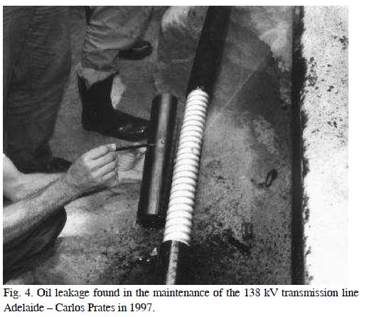
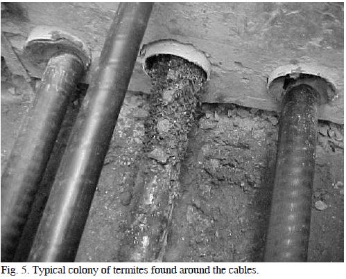
To prevent damages caused by termites on the external sheath of the cables, biologists have been investigating possible reasons for the attacks performed by these insects. Two possible explanations are currently discussed: (i) termites are attracted by the paper (organic material) inside the cable, which serves as food; (ii) termites are likely to build their houses in the vicinity of cables because of the higher temperatures on the external surface of the cable. Fig. 5 illustrates a colony of termites found on the external surface of a 138-kV underground cable.
Regardless of the cause, it is not possible to avoid termite attacks to underground cables already in operation. In the case of new projects, an alternative would be the use of a lead armor, which is more resistant to the corrosion process than aluminum.
B. Maintenance costs
Periodical tests are performed in an attempt to identify the existence of punctures on the PVC layer covering the cable sheath. If a puncture is found, a hole must be opened in the ground for repair. In the last five years, CEMIG has spent about US$75,000.00 per year only with digging services. The periodical tests also include expenses with (a) allocation of personnel to perform power flux studies to keep the transmission system in service during the repair, (b) allocation of personnel to perform the required switchgear operations, and finally (c) mobilization of the maintenance crew to perform the tests, identify the point of the damaged sheath and do the repair.If the maintenance crew fails to identify the existence of a puncture on the PVC layer covering the cable, corrosion process may take place in the aluminum sheath and a short circuit may result as explained before. Interestingly, the short circuit is unlikely to occur at the point where the oil leaks out of the cable. In general, it occurs at the point where the oil volume becomes less than necessary to maintain the electrical insulation during the leakage process, which usually occurs at the higher point along the cable section. This brings great difficulty to the maintenance crew, because two points have now to be repaired along the cable, namely the short-circuit point and the oil-leakage point.
In the last 12 years CEMIG had eight serious problems whose solutions depended on the technical assistance of the cable constructor. Each specialized intervention costs about US$30,000.00 to mobilize team and equipments and US$ 3,600.00 per working day of the specialized team. Normally, after the repair is made, 15 days are necessary for cable treatment (CEMIG's).
When repair is required at a single point of the cable, i.e., if a puncture is identified before any short circuit takes place, the maintenance service is relatively fast and do not require the manufacture of joints. However, if joints need to be manufactured, the whole maintenance work can last two to three months. The costs involved in this case typically exceed US$300,000.00, considering the price of the kits of joints and the cost of services like (a) searches to localize the point of fault including the digging process, (b) joint manufacturing, (c) oil treatment, and finally (d) adjustments in oil pressure.
Of course, some of the cable damages are not due to termites but caused by other agents. For example, an accident occurred in 2007 involving a telephone company that hit two 138-kV underground cables during excavation services. The accident caused oil leakage which ultimately led to a short circuit on the top position of the cable. The total maintenance cost reached US$700,000.00, and the underground cable system became 100 days out of service.
4. A discussion of tests used ince mig to identify damages caused by termites
A. Detection of damages on the insulating cable layer
The procedure to detect damages on the outer insulating cable layer consists in applying a voltage signal between the metallic shield and earth and checking the resulting current. This test requires the underground cable to be out of service, which is costly and disadvantageous. In addition, all grounded points of the shield along the tested section must be disconnected (Fonseca, 2007).
Normally, one day is spent to isolate the cable and perform the test. In the case of detecting any damage, it is necessary to check the line sections between the grounding boxes, which increases the inoperative time of the system.
In a given line section, to discover if there is another hole on the sheath, it is necessary to repeat all the process (dig a trench, access the cable, disconnect the grounded points of the shield, and apply the electric signal again). The work can last up to a week. During this period the electrical system becomes susceptible to failures since the flexibility of the substation is reduced with such transmission line out of the system.
A DC power supply able to provide up to 12 kV (open circuit) and to supply up to 500 mA is used in the tests. The voltage signal is applied between the metallic shield and earth. Initially, the maintenance tests were performed following the prescription of the manufacturer, which recommends the application of a DC signal of 5 kV (Pirelli, 1968). The possible test results would then be classified as follows: (i) if the resulting current does not exceed 10 mA, the cable is considered puncture free; (ii) if the current exceeds 50 mA, the cable is considered damaged; (iii) if the resulting current is in the range of 10 mA-50 mA, there is a chance that the cable layer has some minor puncture. Since, if existent, the puncture would not be easily identifiable, current values are registered and periodical tests are performed in order to check the evolution (or not) of such values.
After years of experience it was decided to reduce the test voltage to 2.5 kV since damages were noted on the external layer of cables even in the absence of punctures that could be related to termites, or in areas that were clearly termite free. This suggests that some of the cable damages could have been induced in the long term by the periodical 5 kV tests.
B. Location of damages on the insulating cable layer
If the sheath current measured in the test described in Section IV.A exceeds about 50 mA, another test is needed to identify the exact location of the puncture. This information is necessary for the maintenance crew to perform the repair (Fonseca, 2007).
The same voltage level previously used to detect the damage of the cable sheath is applied between the metallic shield and earth but now in pulsating mode, with all grounding boxes disconnected. This procedure aims to identify the exact location of current leakage. This is made by means of external sensors that measure the voltage drop on the ground surface above the cables. It is important to note that this test is efficient only before the oil starts to leak. Due to the insulating properties of the oil, the measured current level is significantly reduced after the oil leakage, which makes difficult the correct location of the puncture.
If there is more than one puncture along the cable, the signal intensity is stronger around the puncture that is closer to the voltage source. It is usually harder to identify the location of the other punctures because of low signal intensity (most of the injected currents return to the source via the first puncture).
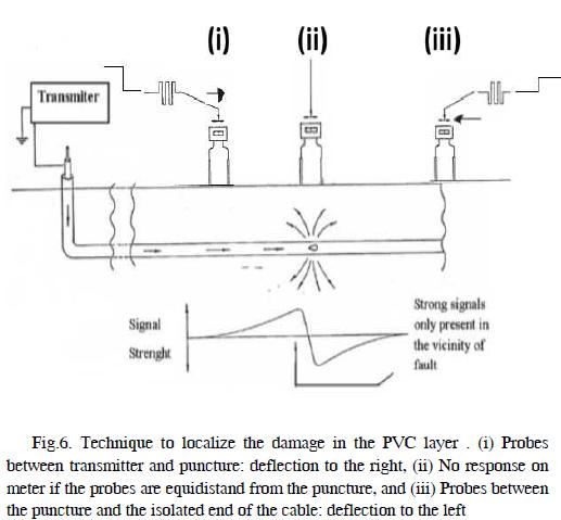
In order to find the failure point, a methodology named ''Popie Technique'' is used (Fonseca, 2007). The sensing instrument consists of a galvanometer whose terminals are connected to a pair of metallic rods (probes) that are placed on the ground surface, approximately 3 m apart. The test procedure, which is illustrated in Fig. 6, is described as follows. The transmitter injects a pulsed voltage signal into the cable sheath. If a puncture exists, a closed loop is created including the transmitter, the cable sheath, the puncture, and the earth return path. As a result, a potential rise is developed at the non-intentional grounding point created at the puncture. The probes are then used to sense the voltage drop on the ground surface. Between the transmitter and the puncture (point A in Fig. 6), the rods measure an increasing voltage as one approaches the puncture (positive deflection on the instrument, pointing to the failure point). Between the puncture and the isolated end of the cable (point C in Fig. 6), the rods measure a decreasing voltage (negative deflection on the instrument, also pointing to the failure point). If the puncture is right between the rods, deflection is null due to symmetry conditions (point B in Fig. 6).
After locating the failure point (point B), a trench is open for the maintenance crew to perform the repair. After that, another test is performed like described in Section IV.A to check if there is another puncture along the outer cable layer. If so, the puncture location procedure is repeated
In general, about 1 hour is spent to detect if the cable sheath is damaged and 2 hours to locate the puncture (considering one line section). The total costs involved range around US$500 per line section.
5. Future perspectives
The test described in Section IV is able to identify the existence of (and locate) punctures on the external PVC layer of underground cables.
However, it has the disadvantage of being an offline test that requires the underground cable to be out of service. Another intrinsic problem of this test is the requirement of applying a high voltage on the PVC layer, which is suspected to be causing a faster aging of the cable insulation with damages similar to those caused by the termites. Furthermore, the cost related to the mobilization of the maintenance crew is very high due to the long time spent during the tests.
It is argued that new procedures are needed for improved on-line, pre-failure detection. Test improvement will hopefully contribute to increase the lifetime of underground cables currently in use, as well as to reduce maintenance costs.
This scenario suggests the need of improved on-line, prefailure detection tests. The priority is to develop a methodology that could identify eventual damages with the transmission line in operation, only putting it out of service to determine the region to be dug in order to perform the necessary repairs.
As an attempt to correlate power deliver, cable temperature, and sheath currents, CEMIG has recently introduced monitoring systems in underground transmission lines to measure core currents and oil pressure. Furthermore, systematic measurements of the sheath currents are currently being performed. The results are still inconclusive, but the idea is to verify if specific operative conditions could lead to an increase in the probability of termite attraction.
Another aspect to be evaluated is the applicability of traveling wave theory as a basis for a test to locate punctures along the cable. Studies related to such topic are under analysis.
6. References
CEMIG's Maintenance Reports 1986 - 2011 (restricted access document). [ Links ]
Fonseca, R.F. ''Detecção de Falha na Capa Protetora de Cabos Isolados de 138 kV'' (in portuguese), Monograph, Curso de especialização em sistemas elétricos de potência (CESEP), Universidade Federal de Minas Gerais (UFMG), 2007. [ Links ]
PIRELLI, (Cabos para Alta e Altíssima Tensão), Catálogo 15-A, 1968. [ Links ]
Rocha, P. E. D. ''Modelagem de Cabos Subterrâneos e Submarinos para Estudos de Transitórios'' (in portuguese), Master's degree dissertation, COPPE, Federal University of Rio de Janeiro, 2007. [ Links ]
Taihan Electric Wire, (Catalogue Of Oil Filled cable And Accessories). Available: http://www.taihan.com (URL). [ Links ]

