


Services on Demand
Journal
Article
 English (pdf)
 Article in xml format
 Article references
 Send this article by e-mail
Indicators
-
 Cited by SciELO
 -
 Access statistics
Related links
-
 Cited by Google
 -
 Similars in
SciELO
Similars in
SciELO -
 Similars in Google
Share

 Permalink
Ingeniería e Investigación
Print version ISSN 0120-5609
Ing. Investig. vol.31 suppl.2 Bogotá Oct. 2011
Portable High Voltage Impulse Generator
Generador Portátil de Impulsos de Tensión.
S. Gómez1, M.P. Buitrago2, F.A. Roldán3
1Works is with the Department of Electrical, Electronical and Computational Engineering, National University of Colombia, Manizales.(e-mail: sgomezar@unal.edu.co).
2Is with the Department of Electrical, Electronical and Computational Engineering, National University of Colombia, Manizales.(email: mpbuitragov@unal.edu.co)
3Is with the Department of Electrical, Electronical and Computational Engineering, National University of Colombia, Manizales. (e-mail: faroldanh@unal.edu.co).
ABSTRACT
This paper presents a portable high voltage impulse generator which was designed and built with insulation up to 20 kV. This design was based on previous work in which simulation software for standard waves was developed. Commercial components and low-cost components were used in this work; however, these particular elements are not generally used for high voltage applications. The impulse generators used in industry and laboratories are usually expensive; they are built to with stand extra high voltage and they are big, making them impossible to transport. The proposed generator is portable, thereby allowing tests to be made on devices that cannot be moved from their location. The results obtained with the proposed impulse generator were satisfactory in terms of time and wave forms compared to other commercial impulse generators and the standard impulse wave simulator.Keywords: Electrical insulation, voltage impulse generator, insulation coordination, power disruption, standardised waves, standardised wave simulator.
RESUMEN
En este trabajo se presenta un generador portátil de impulsos de tensión, diseñado y construido con un aislamiento hasta para 20 kV. El diseño fue basado en un trabajo previo en el cual se desarrolla un software de simulación implementado exclusivamente para ondas de impulso normalizadas. Los componentes empleados fueron en su totalidad de bajo presupuesto, comerciales y algunos generalmente no son usados en alta tensión. Con el generador de impulsos se obtuvieron resultados satisfactorios en cuanto a tiempos y formas de onda, comparados con otros generadores de impulsos comerciales y el simulador de ondas de impulso normalizadas. Los generadores de impulso utilizados en la industria y laboratorios eléctricos son normalmente de gran tamaño, costosos y fabricados para soportar trabajos en extra alta tensión, ocupando demasiado espacio e imposibilitando su transporte. De ahí la importancia de este proyecto, pues siendo portátil facilita realizar pruebas en elementos que no se puedan desplazar de su ubicación.Palabras Claves: Aislamiento eléctrico, Coordinación de aislamiento, Disrupción eléctrica, Generador de impulsos de tensión, Ondas Normalizadas, Simulador de Ondas de Impulso.
1. Introduction
Dielectric strength tests of materials used as electrical insulators are part of widely used and internationally accepted quality tests or trials and they are subject to rules or standards established by corresponding institutions, such as the American Society for Testing of Materials (ASTM) and the International Electrotechnical Commission (IEC).
An insulation coordination study must be done to ensure that high voltage materials tolerate different over voltage through out their life. These techniques are used to select the dielectric strength or insulation level for high voltage materials which must be able to support normalised voltages having different wave forms (the most common types are lightning and switching).
Some authors, (ASTM,2004;IEC, 2001), have stated that impulse voltage generators capable of providing impulse waves large enough to cause a power disruption in the proof element are needed for dielectric strength testing. The tested material's electrical parameters, such as capacitance, can affect magnitude and the wave form applied by the generator. Such capacitance should thus be taken into account when measuring, adjusting and monitoring the voltage wave form.
An impulse generator was designed in (Lora,2008) where most ofthe project components were imported, expensive, not very commercial and built for very specific applications, this being the greatest disadvantage (high implementation costs).
A simulation and numerical optimisation tool was developed in (Carmano et al) which used a minimum squares variant to compare mathematical model output against the output system. This tool calculated electrical circuit values during impulse trials for elements which could be handled. It was stated that the optimisation model would be better as soon as the amount of difficult to obtain experimental data became expanded.
Another article (Electrical Testing Group) has shown how a voltage impulse generator is typically used in techniques for finding faults in electrical transmission and distribution systems in high and medium voltage, called high power reflectometry. It was concluded that an impulse generator allows testing transformers to obtain data representation, associated capacitance and fault detection regarding transformer insulation.
To complement the afore mentioned work, a voltage impulse wave simulator was developed, based on wave normalisation using a graph technique or nomogram studied in (Aguet and Ianoz, 1990) and previously used in the proposed simulation by (Idarraga and Roldán, 2005), where it was only necessary to set the components to be simulated without obtaining preliminary experimental data to conduct an impulse wave analysis. A portable generator was thus designed from simulation results, considering the field application noted above; a portable impulse generator was then constructed giving normalised voltage waves for lightning and switching types, using low-cost implementation components. Because of the small scale design, there were limitations on the voltage generator supply as the generator only delivered up to 20kV impulse voltage waves.
2. Theoretical background
Voltage impulse generators produce waves which can be classified as impulse lightning and impulses witching, with 1.2-250 µs standard front time and 50-2,500 µs for tail time (IEC Standard 60060-1, 1989).
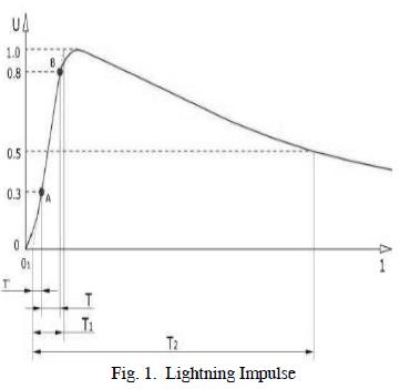
A. Time measurements for a lightning wave
Front timeT1 for a lightning impulse is 1.67 times time interval T (Figure 1, (IEEE Standard 4, 1995)) between the instants when an impulse is 30% and 90% of peak value. Tail time T2 for a lightning impulse is the time interval between virtual origin To and the instant on the tail when the voltage has decreased to half (50%) peak value. Standard tolerances for front and tail time are 30% and 20%, respectively (IEEE Standard 4, 1995; Kuffel and Zaengl, 1970).
B. Time measurement for a switching wave
Front time Tcr, is measured by reaching peak voltage, while tail time Th is measured when maximum voltage drops to 50%. Standard front and tail time tolerances are 20% and 60%, respectively (IEEE Standard 4, 1995; Kuffel and Zaengl, 1970)
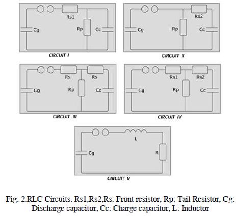
C. Impulse generator
The generalised schemes for a single stage with capacitive, resistive and inductive components are used to generate a standard impulse wave, as shown in Figure 2.
These kinds of circuit give an impulse wave as output (such as that in Figure 3) resulting from subtracting two exponential functions (Aguet and Ianoz, 1990).
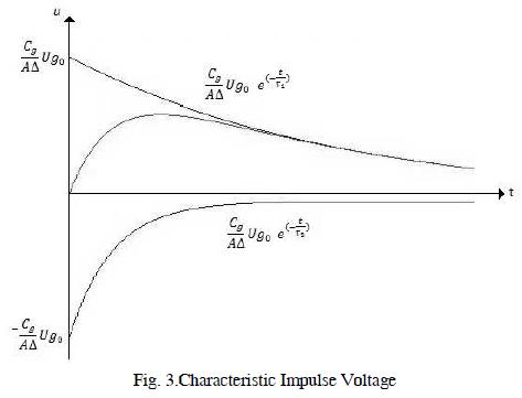
Equation (1) describes this kind of impulse:
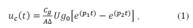
where, p1 and p2 are time constants depending on circuit components (Aguet and Ianoz, 1990).
D. Normalising the wave equation
According to (Aguet and Ianoz, 1990), impulse wave (2) is used for normalisation:
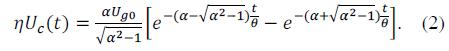
Such simplification is associated with a graph called nomogram or abacus (shown in Figure 4) (Aguet and Ianoz, 1990). This graph relates the determinant factor of voltage impulse shape α, and the determinant coefficient of time θ.
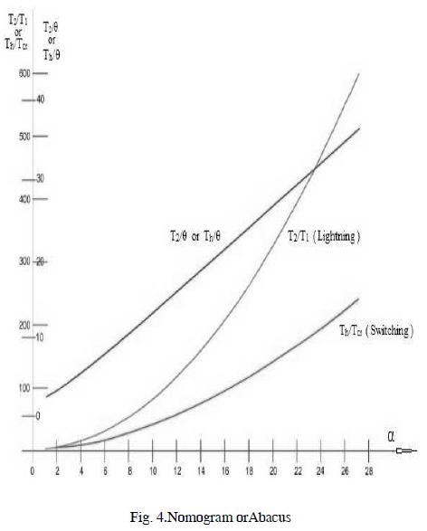
Expressions for T2/T1, T2/θ or Th/θ and Th/Tcr are derived from the nomogram curves used for component and time calculations.
These equations simplify the characteristic component calculation for an impulse generator from the type of known voltage wave or voltage impulse wave regarding the components being used.
E. Characteristic coefficients
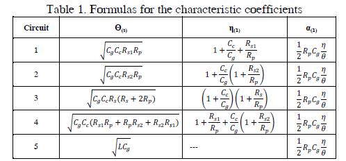
Characteristic coefficients α, θ and η are determined for each type of circuit according to the equations shown in Table 1, which were obtained from (Aguet and Ianoz, 1990).
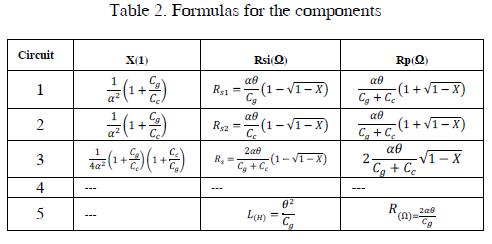
The equations presented in Table 2, which were obtained from (Aguet and Ianoz, 1990), can be used for calculating the components based on the selection of the kind of scheme.
3. Experimental framework
A. Simulator
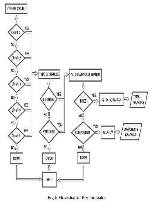
The standardised voltage impulse simulator shown in Figure 5 was designed using the Matlab platform guide. This software allows the user to obtain the wave form for the type of selected circuit from five possible options by determining front and tail times for lightning or switching. The component values can also be obtained the type of impulse, the selected circuit and capacitor values.
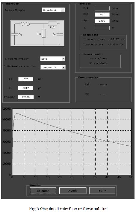
The procedure can be summarised by the scheme presented in Figure 6.
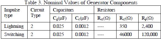
The simulator was used to test commercial generator databases and select appropriate values for space requirements, construction costs and electrical insulation. It was then decided to build the elements using the values described in Table 3.
B. Capacitors
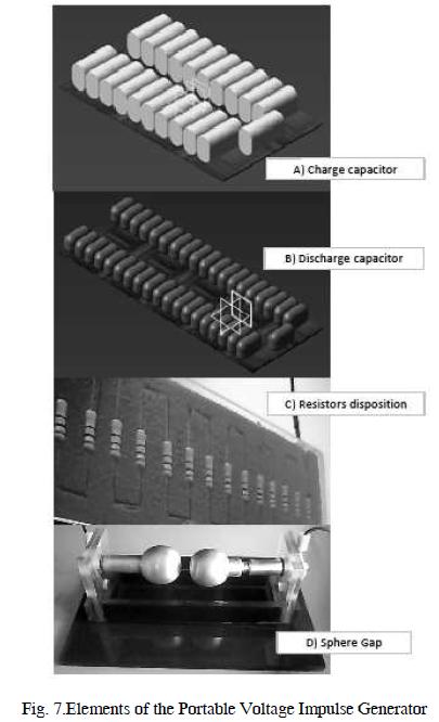
The proposed capacitors had to with stand 20kV voltage and their small capacitances were not commercially available. For each condenser it was necessary to assemble a series of capacitors, insulated from each other by rigid polyurethane foam and encapsulated in acrylic, there by obtaining greater dielectric strength. The building models are shown in Figure 7(a) and 7(b).
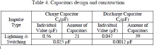
Table 4 summarises the technical characteristics and required amounts of elements used to build the capacitors for the portable voltage impulse generator.
C. Resistors
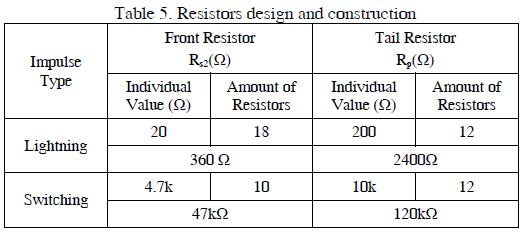
The resistors were made from traditional electronic carbon resistors connected in series to with stand the required stress. The resistors were isolated from each other by using rigid polyurethane foam and encapsulating them in acrylic, there by obtaining greater dielectric strength. Table 5 shows the values for the resistors used; the resistance configuration for lightning is presented in Figure 7(c).
D. Sphere Gap
The sphere gap is used as voltage switch in voltage impulse generators, as in IEEE Standard 4, 1995; Bedoya, 2004). Due to the impulse generator's designed voltage, the sphere gap was proposed for uniform field distribution, using horizontal arrangement and supported on an acrylic structure. The switch could thus be calibrated to the generator's maximum possible voltage.
The spheres had 30mm diameter and maximum 8 mm distance; they were made of aluminium and designed to with stand a maximum 20kV voltage. The sphere gap is shown in Figure 7(d).
E. Power supply
The power supply was formed by a 120/7,000V elevator transformer followed by a Schenkel voltage doubler circuit, as proposed in (Aguet and Ianoz, 1990), to achieve maximum 15kV voltage. The circuit was built using two 0.07µF/8000V capacitors and two rectifier diode shaving 7,000V peak inverse voltage.
4. Results and discussion
The portable voltage impulse generator was tested in the laboratory to confirm that the results conformed to established standards and were with in the tolerances set by them. Simulations were made to test the generator's performance.
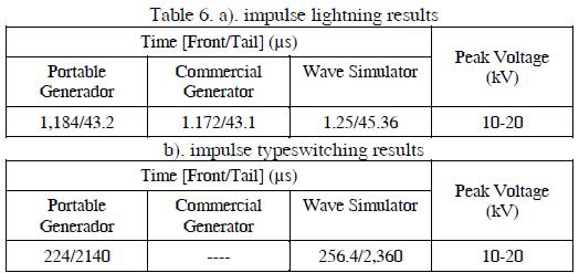
Table 6(a) shows the data obtained from laboratory testing for a lightning impulse using the portable voltage impulse generator. The data obtained for a commercial impulse generator (having the same resistor and capacitor values) and the values calculated by the impulse wave simulator are also presented.
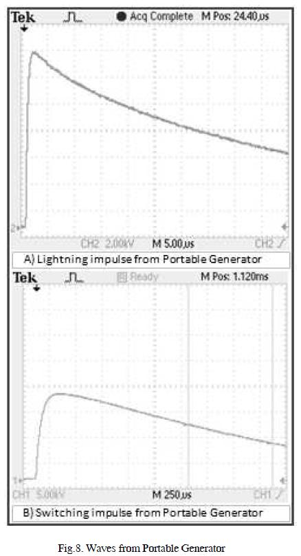
The lightning impulse registered by the oscilloscope as described by (IEC Standard 60060-1, 1989; IEEE Standard 4, 1995) is presented in Figure 8(a) .
Table 6(b) presents the measured switching impulse values from a portable voltage impulse generator compared to those supplied by the impulse wave simulator. The switching impulse recorded by the oscilloscope as described by (IEC Standard 60060-1, 1989; IEEE Standard 4, 1995)is presented in Figure 8(b) .
Lightning and switching impulses were with in established standards when error rate associated with the portable voltage impulse generator was with in such range (Table 7).
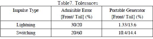
The results showed that the errors calculated for lightning and switching impulses came with in the percentage limits set by the afore mentioned regulations.
The final version of the portable voltage impulse generator components is presented in Figure 9. Tuning tests were performed with a bell-type insulator and the results showed that the generator outputs came within the range of tolerances mentioned above.

5. Conclusions
This paper has presented the design and construction of a portable voltage impulse generator. The proposed generator's performance was compared to that of commercial generators and the established standards for such instruments. The results came within the ranges established by the standards and the generator could thus be regarded as being valid.
The generator satisfied the main objective and needs proposed in this work due to the low cost of its implementation and its comfortable size for use and transport.
Future work will be aimed at expanding insulation components and power supply level to encompass jobs in higher voltage ranges and diversify the number of components to be tested.
6. Acknowledgments
The authors are grateful to the Universidad Nacional de Colombia in Manizales, especially the High Voltage research group for their support in carrying out laboratory practice.
This work was supported in part by the National University of Colombia, Manizales.
7. References
Aguet, M. and Ianoz, M. Haute Tensión, Traité D'Electricité 2éme Édition, París, 1990. [ Links ]
ASTM Standard Test Method for Dielectric Breakdown Voltage and Dielectric Strength of Solid Electrical Insulating Materials Using Impulse Waves, Standard ASTM International D3426-1997, Reapproved 2004. [ Links ]
Bedoya, D. R.; "Diseño y construcción de un espinterómetro para alta tensión - impulso tipo rayo", Engineering Thesis, Department of Electrical, and Electroncial Engineering, Univ. Nacional de Colombia, Sede Manizales, 2004. [ Links ]
Carmona, F.; Jiménez, J. E. and Vázquez, F. "Modelado y simulación del circuito generador de impulsos para el ensayo en transformadores", Department of informatic and numerical analisys, Córdoba, Campus Rabanales, TR-14071. [ Links ]
Electrical Testing Group, "Reflectometría de alta energía mediante el uso del generador de impulsos", Inducor Ingeniería S.A., Buenos Aires, [en línea]. Available on http://www.inducor.com.ar/investigacion.html. [ Links ]
Idarraga, C. and Roldán, F.: "Simulador de Ondas de Choque", presentado en VII Congreso Latinoamericano y IV Iberoamericano en Alta Tensión y Aislamiento Eléctrico, Panamá, 2005. [ Links ]
IEC Electric Strength of Insulating Materials_Test Methods Part 3: Additional Requirements for 1.2/50µs Impulse Test, IEC Standard 60243-3, Jul. 2001. [ Links ]
IEC Standard 60060-1, Nov. 1989; IEC High-voltage test techniques. Part 1: General definitions and test requirements. [ Links ]
IEEE Standard 4 -1995, Aug. 1995;IEEE Techniques for High- Voltage Testing. [ Links ]
Kuffel, E. and Zaengl, W.; High Voltage Engineering. Ed. Londres: Pergamon Press, 1970. [ Links ]
Lora, A.J. "Diseño de un generador de impulsos de alta tensión basado en las normas ASTM-D3426 e IEC-60243-3 para ensayos de rigidez dieléctrica de materiales poliméricos sólidos", Engineering Thesis, Science and Engineering Faculty, Univ. Católica Perú, 2008. [ Links ]

