


Serviços Personalizados
Journal
Artigo
 Inglês (pdf)
 Artigo em XML
 Referências do artigo
 Enviar este artigo por email
Indicadores
-
 Citado por SciELO
 -
 Acessos
Links relacionados
-
 Citado por Google
 -
 Similares em
SciELO
Similares em
SciELO -
 Similares em Google
Compartilhar

 Permalink
Ingeniería e Investigación
versão impressa ISSN 0120-5609
Ing. Investig. v.32 n.1 Bogotá jan./abr. 2012
Evaluating damping elements for two-stage suspension vehicles
Evaluación de los elementos amortiguantes para vehículos con dos etapas de suspensión
Ronald M. Martinod R.1, Germán R. Betancur G.2, and Leonel F. Castañeda H.3
1 Mechanical Engineer, MSc, Universidad EAFIT, Colombia. Engineering teacher, Universidad EAFIT, Colombia. E-mail: rmartino@eafit.edu.co.
2 Mechanical Engineer, MSc, Universidad EAFIT, Colombia. Research assesor, GEMI Research Group, Universidad EAFIT, Colombia. E-mail: gbentac4@eafit.edu.co.
3 Mechanical Engineering, Msc, University of Science of Krakow, Poland. Phd, University of Technology and Life and Sciences in Bydgoszcz, Poland. Professor, Universidad EAFIT, Medellín , Colombia. Coordinator of GEMI Research Group, technical diagnosis line. E-mail: lcasta@eafit.edu.co.
Received: May 23th 2011; Accepted: February 15th 2012
RESUMEN
El trabajo plantea la evaluación del estado técnico de los elementos de amortiguación de un vehículo con dos (2) etapas de suspensión, por medio de modelos numéricos basados en la teoría de sistemas multicuerpo, a los cuales se aplica un conjunto de pruebas virtuales usando el método matemático de vectores propios. Se desarrolla una prueba basada en el análisis modal experimental (EMA) aplicada al sistema físico, como base para validar los modelos numéricos, y posteriormente el estudio se enfoca en la evaluación de la dinámica del vehículo para determinar la influencia del estado técnico de los amortiguadores en cada etapa de suspensión.
Palabras clave: problema de vectores propios, EMA, modelo multicuerpo, parámetros modales, sistema de suspensión, vehículo ferroviario.
ABSTRACT
The technical state of the damping elements for a vehicle having two-stage suspension was evaluated by using numerical models based on the multi-body system theory; a set of virtual tests used the eigenproblem mathematical method. A test was developed based on experimental modal analysis (EMA) applied to a physical system as the basis for validating the numerical models. The study focused on evaluating vehicle dynamics to determine the influence of the dampers' technical state in each suspension state.
Keywords: eigenproblem, EMA, multi-body model, modal parameters, suspension system, railway vehicle.
Introduction
Dynamic systems' modal properties (i.e. natural frequency Ω, damping rate ξ, and modal shapes Γ) are usually obtained by using experimental modal analysis (EMA)based techniques. EMA techniques have been widely documented (Ewins, 2000; He and Fu, 2001; Genta, 2009); EMA is applied to tests based on measuring dynamic system excitation and response according to classical modal analysis theory (Hanson, Randall, Antoni and et al., 2007).
A variation of EMA is the modelling of dynamic systems from mathematical equations describing a particular system's physical aspects. A virtual model's general approach is to numerically integrate the ordinary differential equation constituting the model by using integration algorithms; such approach is usually called simulation or virtual testing (Polach, Berg and Iwnicky, 2006; Genta, 2009).
Numerical simulation enables different types of analysis. The present work focused on developing modal analysis for dynamic systems using the eigenproblem method; this is often used in modal analysis (He and Fu, 2001), as shown below.
Consider a squared matrix [A] of real numbers having size nxn, eigenvalues λr, and corresponding eigenvectors {φ}r (r=1,2,...,n); the {φ}r family consists of independent vectors. The matrix of λr can be expressed in the form [Λ]=diag[{λ}1, {λ}2, ...,{λ}n]. , and the matrix of {φ;}r as [ψ] = diag[{φ}1, {φ}2, ...,{φ}n] The decomposition of eigenvectors produces (He and Fu, 2001)
Equation (1) shows that [A] may be expressed as a diagonal matrix in the form [λ] = [ψ]-1 [A] [ψ]. For all range [A], the only solution satisfying that λr and its corresponding non-null {φ}r exist is when:
This determinant can be expanded, obtaining a polynomial n for λ. The polynomial's roots are λr of [A]. Thus, if equation (2) is valid, then [A] must have n eigenvalues not necessarily different or different to zero (He and Fu, 2001).
Given that matrix system [A] (see equation 1) represents a dynamic system ([M]-1 [K]), having inertia matrix [M] and stiffness matrix [K], then  is equivalent to Ω, and {φ}r is known as representation Γ of such system. λr = 0 indicates that the vibration mode is a rigid body fixed to the ground. If λi = λr, this means that there are identical modal shapes, a phenomenon that occurs frequently in symmetrical structures (He and Fu, 2001).
For a system having multiple degrees of freedom (DoF), the problem of own values derived from the differential movement equations is expressed as:
i.e. the general expression of the eigenproblem. Given that [M] is a defined positive matrix, then it can be decomposed using square root decomposition, [M]=[L][L]T, as ([L]-1 [K] [L]-T)([L]T {φ}) = λ ([L]T {φ}). The general expression of the problem, using terms [M] and [K] from equation (3), becomes a normalised problem for ([L]-1 [K] [L]-T).
Description of the object of study
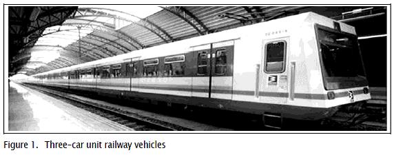
The study concerned the Colombian city of edellín's mass transportation passenger carriage fleet. The railway system has a fleet of 42 three-car units (see Figure 1). Each car has two bogies with two axle-sets; each bogie has two-stage suspension: primary and secondary.
The primary suspension stage consists of inner and outer helicoidal springs, parallel to which there is a vertical hydraulic damper and a set of two blade-guides in each axle box (Figure 2a). The blade-guides provide axle box guidance.
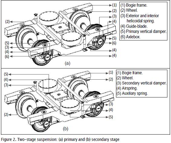
The air springs form part of the secondary suspension stage (Figure 2b), their aim being to keep the height of the car body stable regardless of variations in passengers load. Each air spring is mounted on an auxiliary spring that works in case of the first one's failure. Vertical damping is associated with a hydraulic damper attached to each air spring.
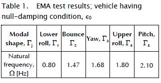
Dynamic characterisation of the vehicle by applying the EMA method
EMA has been used (Buczaj, Walusiak and Pietrzyk, 2007) to determine the behaviour of a vehicle in given operating conditions. Vehicle excitation has been achieved by manual input directly applied to a car body; this consists of simultaneously lifting the corners of a car body by a group of people per corner. Force is applied to the underframe of the car body's side sill or end sill; this concerns applying a rhythmic input force to bring the car to modal shape Γj. Such excitation is created by disconnecting the vehicle's suspension damping elements (removing the primary and secondary suspension's vertical dampers) allowing a car body to be freely excited (Castañeda and Zóltowski 009). The operating condition of the system in the analysis was thus equivalent to null-damping characteristic,  .
.
To better capture transducer (accelerometer) response, they are located at the far ends of a car collinear to a car body's longitudinal plane. A minimum 50Hz sample frequency has been established, including an anti-aliasing filter setting at twice sampling frequency (Gillespie, 2004). The signals recorded as dataset were transformed to the frequency domain by fast Fourier transform (FFT) algorithm to obtain a car body's characteristic frequencies thereby ascertaining the corresponding modal vibration shape (Castañeda and Zóltowski 009; De Silva 007). Table 1 shows the EMA results.
Vertical damping elements for two-stage suspension
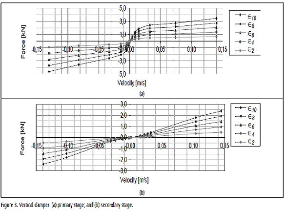
Hydraulic dampers made by Sachs Bogie (nowadays ZF Sachs) provided a vehicle's vertical damping, consisting of:
(i) Primary suspension stage: eight 1-0280-50-865-0 dampers, each adjacent to an axle box; and(ii) Secondary suspension stage: four 1-0280-50-394-1 dampers, each adjacent to a pneumatic spring.
The present work studied a vehicle's dynamic response to determine the influence of the dampers' technical state on each suspension stage. The dampers were characterised by a set of physical laboratory tests; such characterisation of the elements was called nominal damping function,  . A set of four hypothetical functions were established from , representing different technical states regarding damper
  .
.
Hypothetical function  had similar behaviour to but was weighted by a coefficient reducing the damping property of element,
  . It was thus possible to represent the component's technical states through progressive degradation of the damping function (Martinod et al., 2012-1) (see Figure 3).
Development of numeric models
The virtual techniques allow the model to generate information relative to the dynamic behavior, the interaction of the components, and details that are only comparable with physical prototypes (Genta, 2009).
A railway vehicle model can be developed and run on a typical track and instrumented in a virtual environment (Polach, Berg and Iwnicky, 2006; Castañeda and Zóltowski 009). Numerical experiments are a valid source for the necessary data to test the formulated methodologies (Uhl, 2006). These experiments simulate the response of the system from the numeric models of multi-body systems. Recent advances in the field of computational mechanics and numeric methods are directly applied to the analysis of the non-linear mechanics of dynamic systems (Shabana, Zaazaa and Sugiyama, 2008; Castañeda and Zóltowski 009).
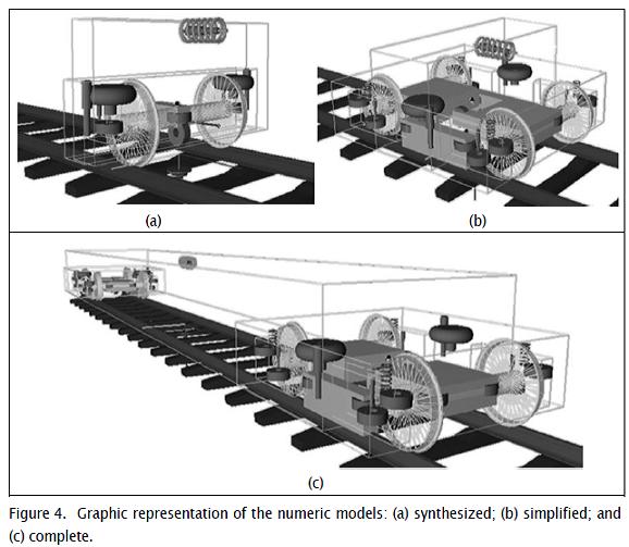
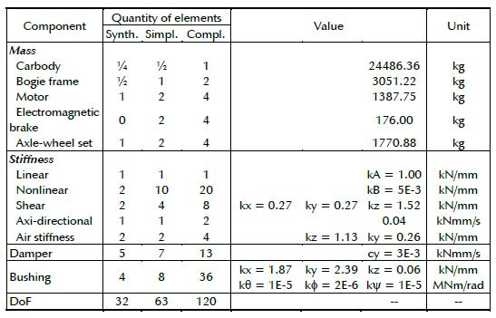
It is important to take into consideration the reach of the investigation at each stage of the work. In early stages, when most of the data is not available, it is not useful to use complex models given that they would be composed of parameters that must be to a certain degree arbitrarily estimated (Genta, 2009). The development of complex computational models is necessary for the detailed study of the behavior of mechanical system. It is in this way that the work is developed in three (3) modeling stages of the object of study: (i) synthesized model; (ii) simplified model; and (iii) complete model.
Each numeric model presents an even more elevated level of complexity in comparison with the model developed in the previous stage; see Table 2. The values for the particular parameters of each model are presented in Appendix A. Each model stage is described as follows:
1.1. Synthesized model
The synthesized is appropriate for a preliminary analysis; it allows directly understanding the effects of the relevant variations of the parameters and it reduces the number of tests required. Further-more, the synthesized model requires a relatively low computing power (Genta, 2009). The synthesized model developed is an abstraction of ¼ of the motor car, see Figure 4(a), which represents the dynamic behavior of the object of study (Gillespie and Karami-has, 2000).
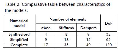
Simplified model
New characteristics must be added to the synthesized model because the physical parameters of the system are gradually defined, obtaining a model with a higher complexity degree. In later stages of the work the need of building a numeric model with greater complexity degree becomes evident (Genta, 2009). The simplified model starts from the synthesized model of the vehicle; it establishes the association of the two synthesized models (aforementioned exposed), the simplified model is constructed by joining two synthetic models, see Figure 4(b), and it describes the system by representing ½ motor car.
Complete model
It can be considered as a true virtual prototype. Virtual techniques allow the model to generate a lot of information regarding not only the response and the dynamic behavior, but also on the interaction between components, capacity details (Genta, 2009; Martinod and et al. 2010). The complex model is developed through the association of the two simplified models (aforementioned exposed) that represent a complete motor car; see Figure 4(c).
It is necessary to point out the guidelines for the correct development of the numeric models. The coherent design of the numerical models allows a correct analysis of the data and it must be designed to evaluate the primary and secondary suspensions under controlled conditions, without affecting the operation and the security of the system. The numerical models are defined following these conditions (Martinod and et al., 2012-2): (i) the load condition (AW0), meaning that the car is empty; (ii) the section track is a straight track and the track irregularities are considered; (iii) the vehicle speed, V=80km/h; and (iv) a variation of the primary and secondary suspensions dampers technical state is assumed (see Figure 3), then, the representation of the different technical states of the dampers through a progressive degradation of the damping function is getting to build the numeric damper model.
The numeric damper model considers the non-linear characteristic (which can be represented by a piecewise linearized force/velocity characteristic) and the stiffness effect of the bushing acting in series with the damper end (see Appendix B). The numeric damper model includes the series stiffness: at low frequencies the series stiffness is effectively rigid, and the behaviour is that of a pure damper; at high frequencies, the damper effectively locks up and the behaviour is that of a pure stiffness.
Validation of the numeric models
A virtual test is performed under the eigenproblem mathematical approach for each of the three defined models. Numeric simulation is done in an operating condition equivalent to the established in the EMA test, meaning that the system has a null-damping capacity, .
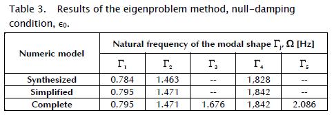
Table 3 shows the results obtained through numeric simulation for each model. It can be observed that the synthetic and simplified numeric models are limited regarding the reach of the analysis given that it is not possible to obtain response from the modal shapes Γj with j=3,5, which are necessary for the stated analysis.
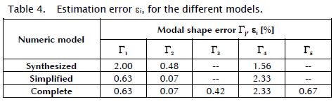
The values of the modal parameter Ω obtained through EMA and exposed in Table 1 represent the reference values of the dynamic system. In consequence, it is possible to directly quantify each estimation error εi for the different models from the existing deviation of the values obtained by the eigen-problem approach in relation to the values obtained by the EMA approach of reference; see Table 3.
From the error values obtained εi < 2.4%, it is possible to assume that the analysis with numeric simulation has appropriate deviation values ε for the reach of the study.
Numeric evaluation of damping elements
It can be observed that the synthesized and simplified numeric models have acceptable error estimation εi values, however these models to not provide sufficient information about the dynamic behavior of the vehicle because they are limited in the dynamic responses of modal shapes Γ3 and Γ5. Therefore, the virtual tests are done to the complete numeric model, using the analysis software VAMPIRE to solve the eigen-problem mathematical approach.
The criteria for the correct performance of the virtual tests must be stated given that the coherent design of the tests allows a correct analysis of the data. The tests are defined in relation to the evaluation separately from the two (2) suspension stages, this is:
(i) Evaluation of the primary suspension stage: consists on a set of numerical simulations, each done with a different damping function of the primary suspension. This means that each simulation evaluates the behavior of the vehicle in a technical state i of the primary suspension; see Figure 3(a). The dampers belonging to the secondary suspension stage conserve their nominal property
(ii) Evaluation of the secondary suspension stage: consists of a set of simulations, each of which is done with a different damping function for the secondary suspension dampers, corresponding to a technical state i of such suspension; see Figure 3(b). The dampers belonging to the primary suspension stage conserve their nominal property
Results of the numeric simulations
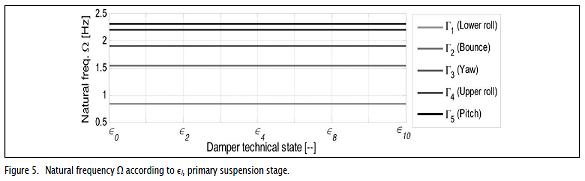
Primary suspension stage
It can be observed (see Figure 5) that the different technical states of the primary suspension vertical dampers do not exert influence on the natural frequency Ω of the car body of the vehicle (forced condition); therefore the parameter Ω presents constant values for each modal shape Γj.
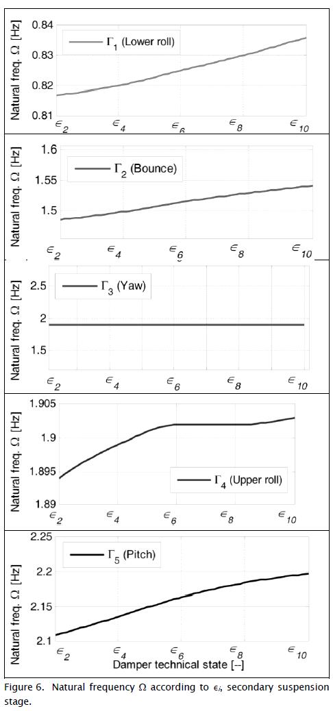
Secondary suspension stage
The values of the vehicle natural frequency are graphically presented (see Figure 6), from which it is possible to obtain the following characteristic relations:
(i) There is a distinguishable influence of(ii) As the damping property of the component diminishes
, the natural frequency Ω declines, obtaining a directly proportional relation.
(iii) The modal shape Γ2 shows two particular characteristics: a distinguishable variation of the frequency respect to
Conclusions
The vertical dampers of the primary suspension stage have total independence respect to the natural frequency of the vehicle vibration Ω, therefore the technical state i of these dampers does not influence the dynamic behavior experienced by the passengers or driver, this is that they are not sensible to the degradation or failure of the dampers in the primary suspension stage.
The vertical dampers of the secondary suspension stage show a direct influence on the dynamic behavior of the modal shapes Γ2 and Γ5, therefore the technical state of the damper i can be tested and estimated through dynamic recording of dataset from measurements in the car body. This means that from the sensors installed in the car body that register the natural frequency Ω appropriately, it is possible to determine the variation of the damping function of the secondary suspension vertical dampers, and in this way infer their degradation or failure.
International standards for railway define the range for deficient frequency ω ≈ [8-10]Hz. The human body is sensible to vertical accelerations (Mitschke, 1983; ISO 2631-1, 1997; Mitschke and Frederich, 1999) see Appendix C; frequencies ω ≈ 10Hz cause excessive oscillations on Γ2, generating significant loss of comfort (Colin, 2006; Castañeda and Zóltowski 009). Comparing the values obtained for the analyzed vibration modes Γi, and under the different technical states of the damper , the natural frequency is Ω < 2Hz. Therefore, the degradation of the damping function for suspension elements does not incur per se in violation to the railway standards.
References
Buczaj, M., Walusiak, S., Pietrzyk, W., Diagnostic Assessment of Technical Condition of the Shock Absorbers in Automotive Vehicles in a Selected Diagnostic Station, TEKA Kom. Mot. Energ. Roln. - OL PAN, Vol. 7, 2007, pp. 59-66. [ Links ]
Castañeda L. F., Zóltowski, B., Estudio de Explotación de Vehículos Ferroviarios, Medellín, Fondo Editorial Universidad EAFIT, 2007, pp. 298. [ Links ]
Colin, C., Longitudinal Train Dynamics, Handbook of Railway Vehicle Dynamics, S. Iwnicki (ed.), Boca Ratón, Taylor & Francis, 2006, pp. 239-278. [ Links ]
De Silva, C. W., Vibration, Fundamentals and Practice, 2nd ed., Boca Ratón, Taylor & Francis Group, 2007, pp. 1036. [ Links ]
Ewins, D. J., Modal Testing: Theory, Practice and Application, Research Studies Press, 2nd ed., Hertfordshire, 2000, pp. 400. [ Links ]
Genta, G., Vibration Dynamics and Control, Mechanical Engineering Series, Torino, Springer Science Business Media, 2009, pp. 812. [ Links ]
Gillespie, T., Karamihas, S., Simplified Models for Truck Dynamic Response to Road Inputs, Heavy Vehicle Systems, Vol. 7, Issue 2-3, 2000, pp. 231-247. [ Links ]
Gillespie, T., Foreword: Road Profiles: Measurement, Analysilst, and Applications, Int. J. of Vehicle Design, Vol. 36, Issue: 2-3, 2004, pp 101-102. [ Links ]
Hanson, D., Randall, R. B., Antoni, J., et ál., Cyclostationarity and the Cepstrum for Operational Modal Analysis of MIMO Systems - Part I: Modal Parameter Identification, Mechanical Systems and Signal Processing, Elsevier, Vol. 21, No. 6, Aug., 2007, pp. 2441-2458. [ Links ]
He, J., Fu, Z. F., Modal Analysis, Oxford, Butterworth-Heinemann, 2001, pp. 305. [ Links ]
ISO 2631-1, Mechanical Vibration and Shock - Evaluations of Human Exposure to whole Body Vibration - Part 4: Guidelines for the Evaluation of the Effects of Vibration and Rotational Motion on Passengers and Crew Comfort of Fixed Guideway Trans-port Systems, International Standards Organization, 1997, pp. 38. [ Links ]
Martinod, R. M., Martinez, A. R., Palacio, M. E., Castañeda, L. F., Jensen, J., Gestaltung von Lastoptimierten Ersatzteilen am Beispiel eines EisenbahneaggonFahrgestells, Konstruktion, Springer VDI Verlag, Apr. 4, 2010, pp. 67-70. [ Links ]
Martinod, R., Betancur, G., and Castañeda, L., Identification of the Technical State of Suspension Elements in Railway Systems, Vehicle System Dynamics: International Journal of Vehicle Mechanics and Mobility, Taylor & Francis, Feb., 2012-1, pp. 2-15. [ Links ]
Martinod, R., Betancur, G., and Castañeda, L Determination of the Technical State of Suspension Elements Based on the OMA-LSCE Method, Ingegneria Ferroviaria, Nr. 1, Jan., 2012-2, pp. 41-54. [ Links ]
Mitschke, M., Performance of Passenger Cars on Uneven Roads, ATZ Automobiltechnische Zeitschrift, Vol. 85, Issue 11, Nov., 1983, pp 695-698. [ Links ]
Mitschke, M., Frederich, F., Improving Riding Comfort of Rail Vehicles for Passenger Traffic, ZEV-Zeitschrift fuer Eisenbahnwesen und Verkehrstechnik - Journal for Railway and Transport, Vol. 123, Issue 4, April, 1999, pp. 133-144. [ Links ]
Polach, O., Berg, M., Iwnicki, S., Simulation, Handbook of Railway Vehicle Dynamics, S. Iwnicki (ed.), Boca Ratón, Taylor & Francis Group, 2006, pp. 359-422. [ Links ]
Shabana, A. A., Zaazaa, K. E., Sugiyama, H., Railroad Vehicle Dynamics a Computational Approach, Boca Ratón, CRC Press Taylor & Francis Group, 2008, pp. 362. [ Links ]
Uhl, T., The Inverse Identification Problem and its Technical Application, Archive of Applied Mechanics, Springer-Verlag, Vol. 77, No. 5, 2006, pp. 325-337. [ Links ]
Nomenclature
Appendix A. Vehicle model parameters of the numeric models.
Appendix B. Numeric damper model performance.
Numeric damper model fitting according to the nominal damping function from physical laboratory tests: (a) Primary vertical damper, frequency excitation 0.2Hz; (b) Primary vertical damper, frequency excitation 1.5Hz; (c) secondary vertical damper, frequency excitation 0.2Hz; and (d) secondary vertical damper, frequency excitation 1.5Hz.
Appendix BAppendix C. Passenger comfort criteria.
All types of transport have different on motion characteristics.
For railway systems, the transversal oscillation, Γ3, is as important as the vertical, Γ2, and they can be analyzed separately because they constitute independent oscillatory behaviors; the same independence exists between Γ2 and the swing behavior, Γ1. The opposite occurs between Γ3 and Γ1, which must be considered jointly because they have dependence elements. The unfavorable conditions that go in detriment of passenger comfort are defined according to the criteria of ξ and :
(i) unsatisfactory limit: ξlim 1 = 5%, value ξ ≤ 5% is perceived as unsatisfactory by the passengers, value ξ >5% determines a positive perception of the passengers;
(ii) deficient frequency range; ωr = [8, 10]Hz, the human body is sensible to vertical accelerations in this range. Frequencies ω≈ 10 Hz, generate excessive oscillations in Γ2, causing significant comfort deficiency;
(iii) oscillation limit of Γ1: ωφ = 0.5 Hz, the vehicle must have a value superior to 0.5 Hz, otherwise there's the risk of producing a movement that causes nausea to the passengers;
(iv) low damping, or even more, instability of the system; and resonance of the components of the vehicle with a periodic excitation.

