


Services on Demand
Journal
Article
 English (pdf)
 Article in xml format
 Article references
 Send this article by e-mail
Indicators
-
 Cited by SciELO
 -
 Access statistics
Related links
-
 Cited by Google
 -
 Similars in
SciELO
Similars in
SciELO -
 Similars in Google
Share

 Permalink
Ingeniería e Investigación
Print version ISSN 0120-5609
Ing. Investig. vol.32 no.3 Bogotá Dec. 2012
The corrosion resistance and microstructure of UBM system-deposited NbxSiyNz thin films
Resistencia a la corrosión y microestructura de recubrimientos de NbxSiyNz depositadas con el sistema UBM
L. Velasco1, J. J. Olaya2, R. Rodríguez-Baracaldo3
1 Leonardo Velasco Estrada. Affiliation: Universidad Nacional de Colombia, Bogotá. MSc. In materials and processes. E-mail: leoveles@gmail.com
2 Jhon Jairo Olaya Florez. Affiliation: Universidad Nacional de Colombia, Bogotá. PhD in Engineering, Universidad Nacional Autónoma de México. E-mail: jjola-yaf@unal.edu.co
3 Rodolfo Rodríguez Baracaldo. Affiliation: Universidad Nacional de Colombia, Bogotá. PhD in Materials Engineering, Universitat Politècnica de Catalunya. E-mail: rodriguezba@unal.edu.co
How to cite: L. Velasco, J. J. Olaya, R. Rodríguez-Baracaldo. (2012). The corrosion resistance and microstructure of UBM system-deposited NbxSiyNz thin films. Ingeniería e Investigación. Vol. 32, No. 3. December 2012, pp. 10-13.
ABSTRACT
NbxSiyNz thin film nanostructure was grown using the unbalanced magnetron sputtering (UBM) technique with varying Si content. Corrosion resistance was evaluated by potentiodynamic polarisation technique in a 3% NaCl solution. Microstructure was analysed by X-ray diffraction (XRD), scanning electron microscopy (SEM) and laser scanning microscopy. Chemical composition was ascertained by X-ray fluorescence (XRF) technique. The results showed that deposition rates increased with higher Si content. A micro-structural change was observed for greater than 5% Si content through the transition from a crystalline to an amorphous structure in the thin films. Corrosion test results demonstrated that the thin films having the highest silicon content had better corrosion resistance.
Keywords: Corrosion, diffraction, spectroscopy, fluorescence, microstructure, microscopy, race track, x ray, thin film, sputtering, polarisation.
RESUMEN
En este trabajo se produjeron recubrimientos nanoestructurados de NbxSiyNz sobre acero inoxidable AISI 304 mediante la técnica del UBM (unbalanced magnetrón - sputtering con magnetrón desbalanceado), variando el contenido de Si, y se evaluó su resistencia frente al fenómeno corrosivo por medio de la técnica de polarización potenciodinámica en una solución al 3% de NaCl. La microestructura de los recubrimientos se analizó por medio de XRD (X ray diffraction - difracción de rayos X), SEM (scanning electron microscopy - microscopia electrónica de barrido) y microscopia láser confocal. La composición química se identificó con la técnica XRF (X ray fluorescence - fluorescencia de rayos X). Como resultado las tasas de depósito se incrementaron con la adición de Si, además se observó un cambio en la microestructura para contenidos superiores a 5% de Si, mediante la transición de un recubrimiento cristalino a amorfo. Finalmente, los resultados de corrosión sugieren que los recubrimientos con un alto contenido de silicio tienen un mejor comportamiento frente a la corrosión del sistema.
Palabras clave: Corrosión, Difracción, Espectroscopia, Fluorescencia, Microestructura, Microscopia, race track, Rayos X, Recubrimientos, Sputtering, Polarización.
Received: February 21th 2011 Accepted: March 7th 2012
Introduction
Several techniques for depositing thin films have been used in recent years; one such is physical vapour deposition (PVD) which efficiently improves materials' mechanical, electrical, optical, and chemical properties (Bhushan et al., 2001; Yang et al., 2008; Kumar and Kaur, 2009; Li et al., 2009; Vyas et al., 2010). Several PVD studies have focused on producing ternary thin films sup-ported on transition metal, silicon and nitrogen (Me-Si-N), im-proving thin film performance and the development of new materials, as mentioned in Ti-Si-N (Ding et al., 2004; Ribeiro et al., 2004), V-Si-N (Veprek, 1997), W-Si-N (Fu, Shen et al., 2005; Fu, Zhou et al., 2005) and Nb-Si-N production (Murakami, Sasaki et al., 2001; Dong et al., 2006; Sandu et al., 2006; Song et al., 2007; Wang et al., 2007).
The unbalanced magnetron (UBM) sputtering technique stands out among PVD processes; it leads to obtaining dense structures at low temperatures and improves adherence, which can in-crease the performance of a coating/substrate system when it is affected by high rates of wear, fatigue and corrosion (Kelly and Arnell, 2000; Safi, 2000; Karthikeyan et al., 2010).
Some studies of NbN thin films produced through the UBM technique have shown good performance in improving steel corrosion resistance (Fenker et al., 2003; Rodil et al., 2007; Olaya et al., 2008; Ramirez et al., 2011). Other studies have focused on the fabrication of Nb-Si-N thin films through PVD techniques and have evaluated their mechanical and electrical properties (Mura-kami et al., 2001; Dong et al., 2006; Sandu et al., 2006; Song et al., 2007; Wang et al., 2007). However, no studies have been found regarding Nb-Si-N thin film corrosion behaviour. Considering this background, the present investigation was aimed at producing NbxSiyNz thin films, varying silicon content. Corrosion resistance was studied regarding microstructure and chemical composition.
Experimental procedure
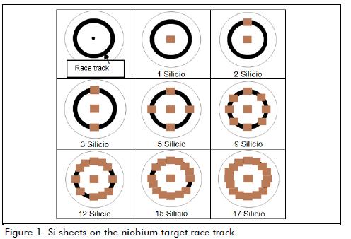
NbxSiyNz thin films were deposited using UBM sputtering. Argon and nitrogen gas flow set at 9 standard cubic centimeters per minute (sccm) and 3 sccm, respectively, were used to generate plasma at 6x10⁻¹ Pa working pressure and 300 mA constant current. A co-sputtering system was for producing the thin films, using Si sheets on a 10 cm diameter niobium target, with 35 rpm substrate holder rotation. Si content in the coating was varied by adding a number of sheets (6x6x2mm) to the area of greatest target erosion, called the race track (as shown in Figure 1).
The substrates were prepared to a mirror finish and cleaned with isopropanol and acetone solutions in ultrasound. The target was cleaned before deposition by 5 minutes' sputtering; an NbxSiy film was deposited to improve thin film adhesion. Deposition rates were studied by Dektak 150 profilometer using 200 micron displacement and 1 mg force in scanning mode (peak assignment) and 6 Å accuracy. The structural study involved X-ray diffraction (XRD) using an X-PertPro analytical system for grazing incidence and Bragg-Brentano configurations and mono-chromatised CuK α radiation (1.540998 Å) working at 45 kV and 40 mA. Morphology was determined with a scanning electron microscope (FEI QUANTA 200 SEM) using high vacuum and 30 KV voltage. The surface was observed by confocal laser scanning microscope (LSM 600).
Chemical composition was evaluated using a fluorescence X-ray spectrometer (Philips PW MagixPro – 2440) with a rhodium tube, at 4KW maximum power. Corrosion resistance was evaluated by potentiodynamic polarisation tests using Gamry 600 equipment, following ASTM G5recommendations (2004). A 3% NaCl solution was used as electrolyte, -0.3 V initial potential, 0.4 V final potential, 0.5 mV/s scan rate and 0.196 cm2 exposed area. A 45 minute solution settling time after sample immersion was allowed for all tests. The corrosion current was evaluated by Tafel extrapolation and porosity rate was determined using equation 1 (Ahn et al., 2004)
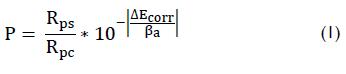
where Rps was AISI 304 uncoated stainless steel substrate polarisation resistance, Rpc coating polarisation resistance, ΔEcorr the difference between coating and substrate corrosion potential and βa the anodic Tafel slope obtained by Tafel extrapolation technique.
Results and Discussion
Deposition rates were evaluated for obtaining ~1.1 µm thickness thin films. Figure 2 shows the deposition rate results for NbxSiyNz thin films, depending on the number of Si layers. A gradual increase in deposition rate was observed when Si was added; this phenomenon has been studied by others (Depla et al., 2006; Eufinger et al., 2006; Depla et al., 2009). This could have been related to increased target polarisation due to secondary electrons emitted by silicon sheets. Such electrons are located on target surface and thus do not interact with the gas, thereby increasing the voltage and accelerating the ions bombarding the target surface.
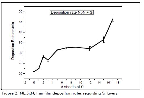
Figure 3 shows δNbN cubic phase XRD spectra with mixed orientation in directions (111) and (200), located at 34.66° and 40.83°. The figure shows a peak at 37.02° corresponding to Nb FCC phase, having (111) orientation. The NbN peaks may have been related to 01-071-0162 in the database and the Niobium peak to reference 01-088-2330. The other peaks corresponded to AISI-SAE 304 steel substrate; however, it should be pointed out that no peak related to silicon or silicon nitride was found, although it was co-deposited. Therefore, amorphous phase formation was likely and has been reported by others (Fu et al., 2005; Dong et al., 2006; Sandu et al., 2006; Song et al., 2007).
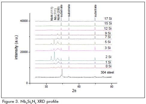
The thin films diagrams having higher silicon content showed that substrate and NbN crystalline phase peaks disappeared, i.e. the thin films exhibited an amorphous phase.
X-ray fluorescence chemical composition analysis showed Nb and Si in the thin film, and Fe, Cr and Ni in the substrate. Figure 4 shows that silicon content increased and niobium content decreased when the number of target sheets increased. This could have been related to a decrease in X-ray diffraction peak intensity. An increase in Si could have promoted the creation of a nanocomposite Si3N4 reducing the amount of NbN in the thin film (Murakami et al., 2001; Dong et al., 2006; Sandu et al., 2006; Song et al., 2007; Wang et al., 2007).
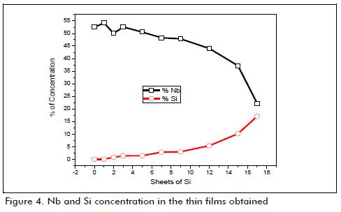
Figure 5 shows SEM images having a homogeneous, compact, low roughness surface copied to substrate topography, as analysed in other studies (Ahn et al., 2002; Liu et al., 2003; Liu et al., 2003). The Figure shows small, isolated areas of delamination in thin films having higher Si content. This could have been attributed to increased residual stress because, as observed in XRD spectra, there was movement to the left of the NbN peak on the plane (111).
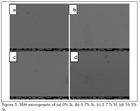
Figure 6 gives a cross-section of the thin films obtained; it shows a structure having columnar growth fitting well to the "T" area in the Thornton model, as described by Ohring (2001) and Martin (2010); however, columnar grain morphology was not observed for higher Si concentrations.
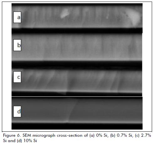
Figure 7 (a-c) shows corrosion using the potentiodynamic polari-sation technique. The thin films had better corrosion resistance than AISI-SAE 304 stainless steel. This could be checked by analysis showing that thin film corrosion potential was more positive and the polarisation curves showed leftward movement on the horizontal axis.
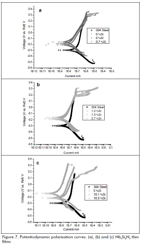
Figure 8 gives corrosion current values calculated by the Tafel extrapolation method and porosity index. The Figure shows a decrease in the corrosion current in the thin films having low Si content; however, the corrosion current had a value similar to that for the substrate for medium Si content. The samples having the highest Si content had lower corrosion current values, indicating better protection against corrosion.
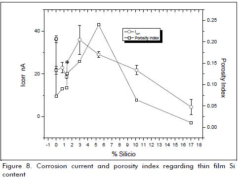
The porosity index was lower in thin films having higher Si content and higher in thin films having medium Si content. These results fit well with the cross-section microstructure, i.e. columnar growth was inhibited in thin films having high Si content.
Thin film corrosion produced by PVD was due to corrosive solution diffusion in the substrate through the grain boundaries between columns and defects (such as pores). Coating degradation was increased by the galvanic coupling created between the substrate and the ceramic (Liu et al., 2003; Galvele, 2005).
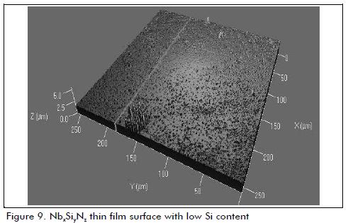
The final thin film surface did not show delamination or surface degradation; this can be seen in Figure 9, obtained with confocal laser microscopy, showing a low Si content coating. The Figure shows a smooth, compact surface free of corrosion products.
Conclusions
NbxSiyNz thin films were successfully deposited and it was found that the deposition rate depended on the quantity of silicon in the niobium target.
Thin film microstructure was related to the quantity of Si deposited. They showed the NbN FCC phase at low quantity and an amorphous structure at high quantity.
The thin films' surface and cross-section had a compact, slightly rough structure. However, columns were only observed in samples having low Si content and they disappeared in samples having high Si content.
NbxSiyNz thin films protected and improved stainless steel corrosion resistance. Surface morphology did not show significant degradation, suggesting that such thin films could be used as a corrosion barrier coating. It should be noted that samples having higher Si content had the best protection against corrosion.
Acknowledgements
The authors thank to Dirección de Investigacíón, Sede Bogotá (DIB) de la Universidad Nacional de Colombia for the financial support this research and to Vicerrectoría Académica of Universidad Nacional de Colombia for the scholarship awarded to Dr. Velasco.
References
S.H Ahn, Y. S. Choi, J.G Kim, J.G Han, A study on corrosion resistance characteristics of PVD Cr-N coated steels by electrochemical method. Surface and Coatings Technology Vol.150, No.2-3, 2002, pp. 319-326. [ Links ]
S.H Ahn, J.H Lee, H.G Kim, J.G Kim. A study on the quantitative determination of through-coating porosity in PVD-grown coatings, Applied Surface Science,Vol.233,No. 1-4, 2004, pp. 105-114. [ Links ]
S.H. Ahn, J.H. Lee, J.G. Kim, , J.G. Han, Localized corrosion mechanisms of the multilayered coatings related to growth defects, Surface and Coatings Technology, V 177-178: 2004 638-644. [ Links ]
J. Wesley Cox. "Wear and Corrosion Resistant Hard Coatings for Non-Cutting Tool Applications". William Andrew Publishing/ Noyes, p. 411. New Jersey, U.S.A. 2001. [ Links ]
D. Depla, S. Mahieu, R. De Gryse. "Magnetron sputter deposition: Linking discharge voltage with target properties." Thin Solid Films,Vol. 517, No.9, 2009, pp.2825-2839. [ Links ]
D. Deplaa, H. Tomaszewskib, G. Buylea, R. De Gryse, Influence of the target composition on the discharge voltage during magnetron sputtering, Surface and Coatings Technology, Vol. 201, No. 3-4, 2006, pp. 848-854. [ Links ]
Ding, X. Z., X. T. Zeng, Liu, Y. C., Yang, Q., Zhao, L. R., Structure and Mechanical Properties of Ti-Si-N Films Deposited by Combined DC/RF Reactive Unbalanced Magnetron Sputtering, Journal of Vacuum Science & Technology A: Vacuum, Surfaces, and Films, Vol. 22, No. 6, 2004, pp. 2351-2355. [ Links ]
Dong Y., Liu Y., Dai J., Li G., Superhard Nb-Si-N composite films synthesized by reactive magnetron sputtering, Applied Surface Science, Vol. 252, No.14, 2006, pp. 5215-5219. [ Links ]
Eufinger, K., H. Tomaszewski, Depla D., Poelman H., Poelman D., De Gryse R.,The d.c. magnetron sputtering behavior of TiO2-x targets with added Fe2O3 or Nd2O3. Thin Solid Films, Vol. 515, No.2, 2006, 683-686. [ Links ]
Fenker, M., Balzer M., Büchi R.V, Jehn H.A, Kappl H, Lee J.-J, Deposition of NbN thin films onto high-speed steel using reactive magnetron sputtering for corrosion protective applications. Surface and Coatings Technology, Vol.163-164, 2003, pp. 169-175. [ Links ]
Fu, T., Shen Y. G., Zhou Z.F., Li K.Y., Surface morphology of sputter deposited W-Si-N composite coatings characterized by atomic force microscopy, Materials Science and Engineering: B, Vol. 123, No.2, 2005, pp.158-162. [ Links ]
