


Services on Demand
Journal
Article
 English (pdf)
 Article in xml format
 Article references
 Send this article by e-mail
Indicators
-
 Cited by SciELO
 -
 Access statistics
Related links
-
 Cited by Google
 -
 Similars in
SciELO
Similars in
SciELO -
 Similars in Google
Share

 Permalink
Ingeniería e Investigación
Print version ISSN 0120-5609
Ing. Investig. vol.32 no.3 Bogotá Dec. 2012
The mechanical design of a transfemoral prosthesis using computational tools and design methodology
Diseño mecánico para una prótesis transfemoral mediante el uso de herramientas computacionales y metodologías de diseño
J. Sánchez1, R. J. Hernández2, J. E. Torres3
1 John Sánchez Otero. Affiliation: Universidad del Norte, Colombia. Mechanical Engineer, Universidad del Norte, Colombia. E-mail: jesf7@hotmail.com
2 Roque J. Hernández. Affiliation: Universidad del Norte, Colombia. PhD. In Mechanical Engineering, University of Texas at Austin, EEUU. MSc. In Mechanical Engineering, Universidad de los Andes. Mechanical Engineer, Universidad del Norte, Colombia. E-mail: roqherna@uninorte.edu.co
3 Jaime E.Torres S. Affiliation: Universidad del Norte, Colombia. PhD in Industrial Engineering, Universidad Politécnica de Valencia, España. International Welding Engineer, International Institute of Welding, Germany. Metallurgic Engineer, UPTC, Colombia. E-mail: jtorres@uninorte.edu.co
How to cite: J. Sánchez, R. J. Hernández, J. E. Torres (2012). The mechanical design of a transfemoral prosthesis using computational tools and design methodology. Ingeniería e Investigación. Vol. 32, No. 3. December 2012, pp. 14-18.
ABSTRACT
Artificial limb replacement with lower limb prostheses has been widely reported in current scientific literature. There are many lower limb prosthetic designs ranging from a single-axis knee mechanism to complex mechanisms involving microcontrollers, made from many materials ranging from lightweight, high specific strength ones (e.g., carbon fibre) to traditional forms (e.g., stainless steel). However, the challenge is to design prostheses whose movement resembles the human body's natural movement as closely as possible. Advances in prosthetics have enabled many amputees to return to their everyday activities; however, such prostheses are expensive, some costing as much as $60,000. Many of the affected population in Colombia have scarce economic resources; there is therefore a need to develop affordable functional prostheses.
The Universidad del Norte's Materials, Processes and Design Research Group and the Robotics and Intelligent Systems Group have been working on this line of research to develop modular prostheses which can be adjusted to each patient's requirements. This research represents an initial methodological approach to developing a prosthesis in which software tools have been used (the finite element method) with a criteria relationship matrix for selecting the best alternative while considering different aspects such as modularity, cost, stiffness and weight.
Keywords: Design, transfemoral prosthesis, finite element, design methodology.
RESUMEN
El desarrollo de prótesis para extremidades inferiores es reportado profusamente en la literatura científica actual. Hay disponible una gran variedad de diseños de prótesis de miembro inferior, que van desde un mecanismo de rodilla de eje simple hasta complejos mecanismos con microcontroladores, fabricados con una gama de materiales que van desde los ligeros de alta resistencia específica, como la fibra de carbono, hasta tradicionales como el acero inoxidable. Sin embargo, el reto es diseñar prótesis cuyo movimiento se asemeje, lo más posible, al del cuerpo humano. El desarrollo de prótesis ha hecho posible que muchas personas ampu-tadas vuelvan a desempeñarse en sus actividades; sin embargo, estas prótesis son de costos elevados, algunas pueden llegar a valer hasta 60 000 dólares. Gran parte de la población afectada en Colombia es de escasos recursos, por lo tanto se hace necesario el desarrollo de prótesis funcionales de bajo costo.
El Grupo de Investigación en Materiales, Procesos y Diseño y el Grupo de Robótica y Sistemas Inteligentes de la Universidad del Norte vienen trabajando en esta línea de investigación con el objetivo de desarrollar prótesis modulares que se puedan ajustar a los requerimientos particulares de cada paciente. Este trabajo corresponde a una primera aproximación metodológica para el desarrollo de una prótesis en la que se utilizaron herramientas computacionales (método de los elementos finitos) junto con una matriz de relación de criterios para seleccionar la mejor alternativa teniendo en cuenta diferentes aspectos como modularidad, costo, rigidez y peso.
Palabras clave: Diseño, Prótesis Transfemorales, Elementos Finitos, Metodologías de Diseño.
Received: December 7th 2011 Accepted: November 9th 2012
Introduction
Antipersonnel landmines (APLs) represent one of the leading causes of amputation worldwide. These devices have become a social problem, confirmed by the International Committee of the Red Cross (ICRC); APLs have caused more deaths or injuries to date than nuclear weapons. Furthermore, according to the
World Health Organization (WHO), it has been estimated that 26,000 people are killed or disabled by APLs each year.
The use of APLs in Colombia by those involved in the armed conflict has increased significantly. This increase has been particularly caused by these devices' low cost; it has been estimated that a homemade mine costs around $10,000 COP, while disabling it requires spending 500% in excess of this (Hernandez, 2003).
There are usually no means to help a victim in case of injury following an explosion caused by a landmine. Transport is often limited due to a victim's (very probable) rural location, thereby causing delay in a wounded victim's arrival to a medical facility; it thus frequently takes hours or even days to receive medical care. Amputation is often the only medical resource that ensures survival (Hernandez, 2003).
Amputation above the knee means that a person almost com-pletely loses stability. Many prosthetic models have been invented to meet such need; however, conventional models cause inflammation, severe muscle aches and hip and spine problems because they lack elements for absorbing a reaction force when coming into contact with a supporting surface. More advanced models are capable of controlling knee position and speed of movement and damping a reaction force; these would include C-leg, Endolite Adaptive, Ossur Total Knee 2000, Ossur Mauch XG, and Prolite Smart Magnetix. However, their costs are very high (i.e. around $70-130 million COP).
Many affected people do not use a conventional prosthesis be-cause of the cost involved; instead, many of them resort to using low technology/low-cost prostheses designed and manufactured with very poor technical and ergonomic criteria.
In trying to resolve this problem, the Universidad del Norte's Materials, Processes and Design Research Group (GIMYP) and the Robotics and Intelligent Systems group have been working on a macro research project entitled, "The Design and construction of a prototype lower limb prosthesis with reaction force controlled by a magnetorheological damper." Two prosthetic mechanical designs were developed for improving stability and reducing the reaction force directly affecting an affected person's stump.
Methodology
Initial research involved collecting and analysing information for constructing the prosthetic design database (i.e. know-how), setting the state of the art and identifying opportunities for improvement in terms of ergonomics, stiffness, modularity and weight. A second stage involved prosthesis component functionality; the relationship between them was determined using current design methodologies.
Design requirements and prosthesis component functionality and relationships were identified; two prosthetic models or mechanical alternatives were then developed whose central features focused on performance regarding functionality, modularity, stiffness, weight, ease of fabrication and maintenance. Previous design studies were used as reference (Espejo, 2007; Correal, Palacio and Salazar, 2006; Enriquez, Arreguin, Mendez, and Trejo, 2007). Research by Zhang, Clowers and Powell (2006) was taken as reference for defining age, weight and height ranges. The aforementioned study was performed on 11 healthy subjects (5 women and 6 men, average age 27.4 ± 7.8 years, average weight 72 ± 13.4 kg, average height 1.76 ± 0.08 m) for determining the maximum reaction force exerted by the ground (as experimental measurements were not performed).
Previous research has determined ground reaction force on the hindfoot (Giakas and Baltzopoulos, 1997; Simpson and Jiang, 1999; Collado, 2005; Keefer, King, Powell, Krusenklaus and Zhang, 2008; Winby, Lloyd, Besier and Kirk, 2009). However, these studies reported very differing values because different methods and techniques were used in each; measurements were also influenced by age, weight, gender, height and gait speed (Bennetti and Duplonk, 1993). In this regard, a single reference was thus selected which would meet what was required.
The maximum reaction force was determined at a later stage; this was used to validate the models. The finite element analysis method was used for validation, using the Solidworks (CAD) software tool which incorporates an application called Cos-mosWorks (CAE). This application allows for the evaluated models' components stress, strain and lifetime to be predicted and optimising material service by reducing component weight. A criteria relationship matrix was used for selecting the most feasible or best response in the tests performed and regarding the factors evaluated.
Results
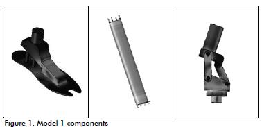
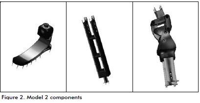
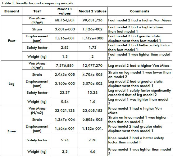
Two mechanical prosthesis designs were evaluated (Figures 1 and 2) having a maximum 1000 N force. The materials used to validate the models via CAD and CAE simulation were rubber, carbon fibre and AISI-316 steel, as described in previous research (Knight and Tinoco, 2005). The models were evaluated for each component (foot, leg and knee). Static and a fatigue tests were performed.
Static analysis
The foot was the first component validated; prosthetic foot models must be light and should withstand both room temperature and normal high and low temperature fluctuations. They must be robust, having a large elasticity modulus, making them able to resist deformation (Ascencio and Gomez, 2004). Foot model 1 was designed using AISI-316 steel while model 2 was designed using carbon fibre with rubber damping. Leg models 1 and 2 were made with AISI-316 and designed to lessen prosthesis weight. For example, model 1 consisted of a tube-leg with hollow centre to reduce component weight. The knee was evaluated as it is one of the most important components due to being involved in an amputee's stability when the knee is being stretched or bent; the safety factor must thus be fairly reliable. Table 1 gives static test results.
Both models could be worthwhile in terms of design studies and geometric optimisation; however, prosthesis components were subjected to a fatigue test to select the most viable model and developing a criteria relationship matrix was also considered.
Fatigue analysis
AISI-316 steel was used for the fatigue test and nominal force (1,000 N) used in the static test varied between 1,000 N and 0 N for a period of 1,000 cycles to determine each component's load factor and lifetime.
Fatigue analysis for model 1
Figure 3 (foot model 1) shows a rating of 60 million cycles (significant in that it suggested that the component has an infinite lifetime) and load factor of 9 (i.e. nominal force would have to be increased nine times for the material to fail).
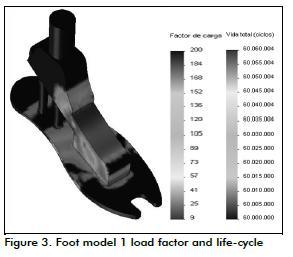
Figure 4 shows that leg model 1 lifetime was 60,000,000 life-cycles and load factor 86. These values led to considering possible over-dimensioning of the work piece.
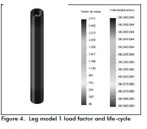
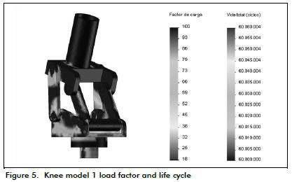
Figure 5 shows knee model 1 had a load factor of 18 and infinite lifetime.
Fatigue analysis for model 2
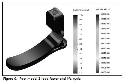
Figure 6 indicates that that foot model 2 load factor was 11. The component had an infinite lifetime involving 60,000,000 cycles.
Leg model 2 had a load factor of 47, a quite significant value allowing optimisation in terms of geometry and weight ratio (see Figure 7).
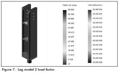
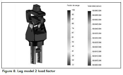
Figure 8 shows that knee model 2 had a load factor of 22. The life-cycle results shown in the same Figure suggested that the component had an infinite lifetime.
Criteria relationship matrix
A criteria relationship matrix was used for final evaluation to select the most viable alternative. Each factors used is explained below.
Modularity: led to studying, understanding, configuring, or viewing a system of modules interacting with each other and achieving a common goal. Each system element had to be independent from the rest but able to communicate with one or all of the other elements by adapting well-defined input and output. System modularity was evaluated by component adaptability displayed when faced with user changes.
Maintenance: was related to effective action to improve prosthesis' operational aspects, such as functionality, safety and comfort. This enabled streamlining operating costs. Maintenance had to be periodic and on-going, as well as preventative and corrective. Component geometry and the number of elements and joints needed to maintain prosthesis' proper functioning were consid-ered for evaluating this factor.
Stiffness: was a solid or structural element's ability to withstand exertion without acquiring large deformation or displacement. The element's load factor was taken as reference when measuring this criterion regarding prosthesis components.
Ease of fabrication: the ease of component or model fabrication. Evaluation was based on element shape and manufacturing processes used to obtain a desired shape.
Weight: measures component mass; its value was obtained from the component volume provided by the software tool and the density of the material used.
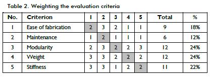
Once factors were defined, they were compared to each other (Table 2). Based on the stated objectives, it was decided which factor was more or less important in relation to the others to estimate their share of influence in decision-making. Ratings were assigned as follows: minor importance = 1, equal importance = 2, greater importance = 3.
When the alternatives had been compared to each other, each was given a rating in relation to the assessment criteria; this value was then multiplied by factor weighting or importance. Rating was assigned as follows: -1 = worse, 0 = equal, 1 = best.
The most viable alternative was model 1, based on the result, and taking the simulations, benchmarking, and the criteria relationship matrix into account.
Conclusions
Considering that results vary depending on experimental conditions, extreme care should be taken when using literature references to guide modelling or design. Only one set of guidelines was used to determine the maximum reaction force; moreover, because test conditions used in several studies were different, using different data sources for this application could increase the margin of error.
The software tools used for the simulation were crucial for verifying mechanical design reliability. However, design decisions could not just be based on simulation results; they had to be validated with experimental data. Field tests for validating the final design were vital and are mandatory.
One advantage of simulation is that models can be progressively improved based on the results obtained; one example would be component optimisation in relation to weight and shape, given that the values obtained allowed changes.
Fatigue test results ( component lifetime and load factor) led to concluding that both models could still be optimised in terms of their geometry and weight.
Validation by the finite element method minimised costs and the time required for studying each material used (Cely and Diaz, 2007), thereby having a significant impact on component lifetime and stiffness. Factors such as weight, stiffness and modularity had greater relevance or impact on the final product than maintenance and ease of fabrication in this study.
It is recommended that further experimental tests be performed, e.g. reaction force measurements through plantar pressure and force measuring systems (Collado, 2005; Ramos, 2007; Diaz Torres, Ramirez, Garcia and Alvarez) to provide more accurate simulation for obtaining designs which are as functional as possible. These tests would allow working with other materials and designing experiments using several combinations of prosthetic elements, aimed at achieving an optimal design.
References
Ascencio, O., and Gómez, D., Diseño y Modelamiento de pie para prótesis de miembro inferior adaptable a prótesis comerciales o estándares con sistema de amortiguación., BSc Electronic Design and Automation Engineering thesis, Universidad de La Salle, 2004. [ Links ]
Bennetti, P., and Duplonk, L., Pressure distribution beneath the human foot. J Am Podiatr Med Assoc; Vol. 83, 1993, pp. 674 - 678. [ Links ]
Caballero, D., and Tinoco, R., Selección de materiales para una prótesis de extremidad inferior con fuerza de reacción magne-toreologicamente controlada., BSc Mechanical Engineering thesis, Universidad del Norte, 2005. [ Links ]
Cely, M., and Díaz, A., Diseño y análisis por el método de elementos finitos y tomografía computarizada de una prótesis transtibial., Scientia et Technica Año XIII, No 36, 2007. [ Links ]
Collado, S., Dynamometrics Platforms. Aplicaciones., Biociencias, Revista de la Facultad de Ciencias de la Salud, Vol. April 3, 2005, pp. 1- 15. [ Links ]
Correal, S., Palacio, L., and Salazar, I., Análisis FEA de prótesis de rodilla policéntrica, Universidad EAFIT. Avances en Sistemas e informática, Vol. 3, No. 1, June 2006, pp. 35-38. [ Links ]
Díaz, A., Torres, A., Ramírez, J., García, L., and Álvarez, N., Descripción de un sistema para la medición de las presiones plantares por medio del procesamiento de imágenes fase I. Revista EIA, No 6, 2006, pp. 43 - 55. [ Links ]
Enríquez, J., Arreguin, E., Méndez, A., and Trejo, L., Diseño y construcción de una prótesis de rodilla con pistón magnetoreologico, 8th Congreso Iberoamericano de Ingeniería Mecánica, Cusco, 2007. [ Links ]
Espejo, A., Construcción de un prototipo final de pie para prótesis transfemoral., BSc Electronic Design and Automation Engi-neering thesis, Universidad de La Salle, 2007. [ Links ]
Giakas, G., and Baltzopoulos, V., Time and frequency domain analysis of ground reaction forces during walking: an investigation of variability and symmetry, Gait & Posture, Vol. 5, 1997, pp. 189 - 197. [ Links ]
Hernández, G., Minas Antipersonales (M.A) en Colombia Costo Físico y Emocional., Fundación Universitaria Manuela Beltrán, Umbral Científico, No 002, Junio, 2003. [ Links ]
Keefer, M., King, J., Powell, D., Krusenklaus, J., and Zhang, S., Effects of modified short-leg walkers on ground reaction force characteristics. Clinical Biomechanics, Vol. 23, 2008, pp. 1172 - 1177. [ Links ]
Ramos, M., Utilidad del análisis tridimensional de la marcha como sistema evaluador del estado clínico y funcional de pacientes sometidos a artroplastia de rodilla., MD thesis, Universidad Complutense de Madrid, 2007. [ Links ]
Simpson, K.J, and Jiang, P., Foot landing position during gait influences ground reaction forces, Clinical Biomechanics. Vol. 14, 1999, pp. 396 - 402. Elsevier. [ Links ]
Winby, C., Lloyd, D., Besier, T., and Kirk T., Muscle and external load contribution to knee joint contact loads during normal gait. Journal of Biomechanics, Vol. 42, 2009, pp. 2294 - 2300. [ Links ]
Zhang, S., Clowers, K., and Powell, D., Ground reaction force and 3d biomechanical characteristics of walking in short-leg walkers. Gait & Posture, Vol. 24, 2006, pp. 487 - 492. [ Links ]
