


Serviços Personalizados
Journal
Artigo
 Inglês (pdf)
 Artigo em XML
 Referências do artigo
 Enviar este artigo por email
Indicadores
-
 Citado por SciELO
 -
 Acessos
Links relacionados
-
 Citado por Google
 -
 Similares em
SciELO
Similares em
SciELO -
 Similares em Google
Compartilhar

 Permalink
Ingeniería e Investigación
versão impressa ISSN 0120-5609
Ing. Investig. vol.32 no.3 Bogotá dez. 2012
A comparative study of two models for the seismic analysis of buildings
Estudio comparativo de dos modelos para análisis sísmico de edificios
A. Luévanos1
1 Arnulfo Luévanos Rojas. Affiliation: Facultad de Ingenieria, Ciencias y Arquitectura, Universidad Juárez del Estado de Durango, Mexico. Engineering Doctor with specialty in Planneation and Construction, MSc in Planneation and Construction, Civil engineer, Universidad Juárez del Estado de Durango, Mexico. MSc in Structures, Escuela superior de Ingenieria y Arquitectura del Instituto Politécnico Nacional, Mexico. MSc in Administration, Facultad de Contaduría y Administración de la Universidad Autónoma de Coahuila, Mexico. E-mail: arnulfol_2007@hotmail.com
How to cite: A. Luévanos. (2012). A comparative study of two models for the seismic analysis of buildings. Ingeniería e Investigación. Vol. 32, No. 3. December 2012, pp. 37-41.
ABSTRACT
This paper presents a model for the seismic analysis of buildings, taking two lumped masses at each level in a structure's free nodes and comparing them to the traditional model which considers lumped masses per level, i.e., a mass for each floor of the entire building. This is usually done in the seismic analysis of buildings; not all values are conservative in the latter, as can be seen in the table of results. Both models took shear deformations into account. Therefore, the usual practice of considering a lumped mass per each level would not be a recommended solution; using two lumped masses per level is thus proposed and is also more related to real conditions.
Keywords: modal analysis, spectral analysis, eigenvalues and eigenvectors, modal participation factor, spectral acceleration, maximum normal coordinate vector
RESUMEN
En este documento se presenta un modelo para análisis sísmico de edificios en el cual se toman dos masas concentradas por cada nivel aplicadas en los nodos libres de la estructura y se compara con el modelo tradicional, que considera las masas concentradas por nivel, es decir, una masa por cada piso de todo el edificio, que es como normalmente se hace; en este último no todos los valores son conservadores, como se puede notar en la tabla de resultados del problema considerado. Ambos modelos toman en cuenta las deformaciones por cortante. Por lo tanto, la práctica usual de considerar las masas concentradas, una por cada nivel, no será una solución recomendable, y se propone el empleo de tomar dos masas concentradas por nivel, que se apega más a la realidad.
Palabras clave: análisis modal, análisis espectral, valores y vectores característicos, factor de participación modal, aceleración espectral y vector de coordenadas normales máximas.
Received: June 23th 2011 Accepted: November 9th 2012
Introduction
Three types of methods can be used for the seismic analysis of building structures: simplified, static and dynamic methods. The simplified method is applicable to regular structures standing less than 13 m high and simultaneously fulfilling all requirements indicated by the building regulations. The static method is applicable to buildings whose height is less than or equal to 30 m for regular structures and irregular structures standing less than 20 m high; these limits increase to 40 m and 30 m, respectively, for structures sited on rocky terrain. The dynamic method consists of the same basic steps as that for the static method, with the reservation that applicable lateral forces in the floors' centre are determined from a structure's dynamic response. Modal spectral analysis and step-by-step analysis or calculating responses having specific acceleration registries can be used for the dynamic method (Zárate, Ayala et al., 2003).
This study was aimed at presenting a model which would take into account a building's two masses per level applied to free nodes and considering three degrees of freedom at the joints, comparing it to the traditional model taking one mass per level and considering one degree of freedom per floor (horizontal displacement per level). Both models took shear deformation into account.
Analytical development
Equations of motion in a structural dynamic system
Overall equations of motion in a structural dynamic system, (Przemieniecki, 1985) without including border conditions, can be written in matrix form as follows:
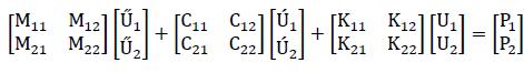
where: U1 is a vector of n x 1 generalised absolute displace-ments (unknown) corresponding to non-restricted degrees of freedom "n", U2 is a vector of m x 1 generalised absolute dis-placements (null or known) corresponding to the degrees of freedom in supports "m", Mij, Cij, Kij are mass matrices, damping and stiffness are associated with degrees of freedom "n" and/or "m" respectively, P1 is a vector of n x 1 representing associate dynamics' requirements regarding degrees of freedom "n", P2 is a vector of m x 1 representing associate reactions (unknown) to the supports' degrees of freedom "m".
Considering linear systems involving orthogonality for stiffness (K ), mass (M) and damping (C) matrices, it is convenient to diag-onalise the system of equations of motion to transform it into a normal modal coordinate system. A system having free un-damped vibration, which can exist in the absence of any excitation of the supports, would give:
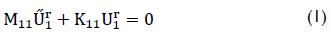
where M11 is a mass matrix corresponding to non-restricted degrees of freedom "n", K11 is a stiffness matrix corresponding to non-restricted degrees of freedom "n", U1r is a vector of relative displacement and Ü1r is a vector of relative acceleration.
The solution of equation (1) is defined (by Aguilar Falconi, 1998; García Reyes, 1998) as:
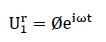
where ω is natural vibration frequency, θ is a modal vector associated with "ω", i √-1 and t is time.
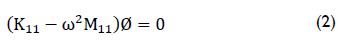
The values of ω and θ are determined by resolving eigenproblems as:
The modal participation factor "Ln" (Clough, Penzien, 1975; Bazan, Meli, 1998) can be expressed as:
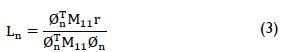
where θTn is the transposed vector of a modal vector corre-sponding to the mode "n" and r is a pseudostatic influence vector.
The normal maximum coordinates of the system for each mode "(Yn)max" are:
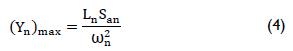
where San is spectral acceleration corresponding to mode "n".
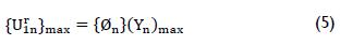
The vectors corresponding to maximum relative displacement vector components for each mode "{Ur1n}max" can be defined as:
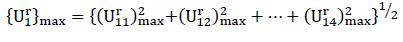
The maximum value of the vector of relative displacements in structural system "{Ur1}max" is:
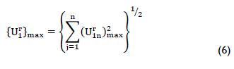
or
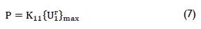
The value of the equivalent mechanical elements acting in free nodes "P" (McCormac, 2007) is:
The mechanical element components acting on members "F" (Tena Colunga, 2007) are:
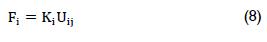
where Ki and Uij are each bar's stiffness and displacement.
Application
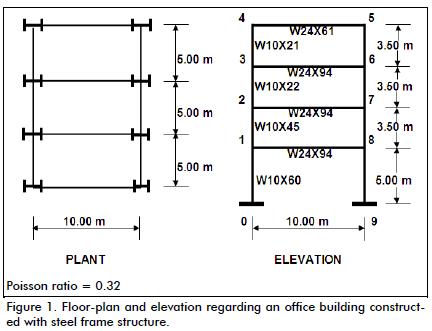
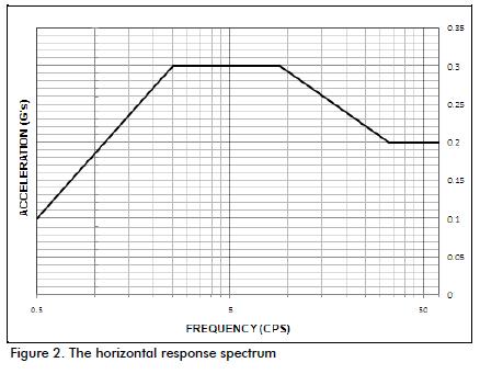
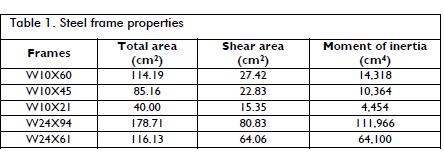
An example of the dynamic seismic design method is presented, using two different models, considering shear deformation for an office building built with a steel frame structure. The analysis is only developed transversally. Figure 1 shows the office building's floor-plan and elevation and Figure 2 shows the horizontal response spectrum, representing soil movement where the building is supported. Table l shows the steel profile properties.
The load to be considered in the analysis by level was:
Weight of level 1 = 6,867 N/m2
Weight of level 2 = 5,886 N/m2
Weight of level 3 = 4,905 N/m2
Weight of level 4 = 2,943 N/m2
Elasticity modulus = 20,019,600 N/cm2
Model 1
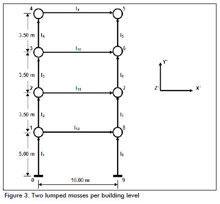
The beams and columns were considered for analysis in this model, taking into account two lumped masses per level applied in free nodes and considering three degrees of freedom at each joint (horizontal displacement, vertical displacement and rotation). The building was only analysed in a transversal direction. Figure 3 gives the mathematical model.
Model 2
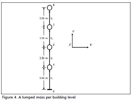
This model considered that the beams were rigid compared to the columns and, therefore, the beams did not influence dynamic analysis of the building. It also considered one degree of freedom per level, i.e. horizontal displacement (Luévanos Rojas, 2010). The mathematical model is presented in Figure 4.
The mass and stiffness matrices for each member were evaluated (Appendix; Luévanos Rojas et al., 2010) followed by the change of local system to overall system. The mass and stiffness matrices in each member's general system were then coupled and the system's general matrix obtained. This general matrix was organised to separate the degrees of freedom in the structure (M11 and K11) and degrees of freedom in the supports (M22 and K22). A similar transformation was applied by exchanging row and column matrices (permutation matrix).
Ignoring the effect of damping in free vibration, as in equation (1), being a vector (24x1 for model 1 and 4x1 for model 2) of relative displacements corresponding to the building's structural system degrees of freedom, then the eigenvalues and eigenvectors were obtained by solving the determinant resulting from equation (2).
MATLAB software was used for solving the determinant and the roots of the polynomials. Table 2 shows the first four modes of the sixteen for model 1 (M1) and the four modes for model 2 (M2) are presented in.
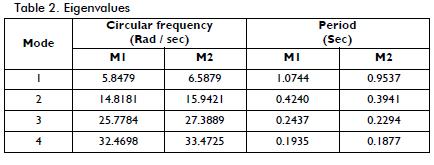
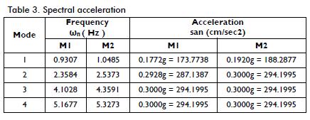
Table 3 shows the spectral accelerations of the first four modes of M1 and the four modes of M2.
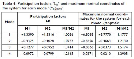
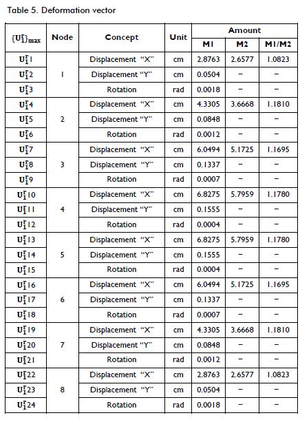
Equation (3) gave modal participation factor "Ln". The maximum normal coordinates of the system for each mode "(Yn)max" were located by using equation (4). The first four values for the M1 and the four values for M2 are shown in Table 4. The maxi-mum relative displacement vector components for each mode "{Ur1n}max" were given by equation (5) and the maximum value of the structural system relative displacements' vector for building "{Ur1}max" was obtained by equation (6). These values are shown for both models in Table 5.
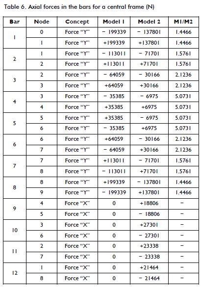
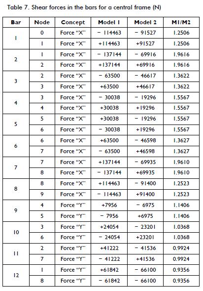
Once the deformations were obtained, equation (7) was used to find the values of the forces in "X", the forces in "Y" and mo-ments; these were applied at the free joints. Such effects were equivalent to what would have occurred due to a movement in the soil where the building was located. The mechanical elements at the joints on the members of the whole building were deter-mined by equation (8) and then obtained for each of the build-ing's rigid frames. The axial forces, the shear forces and the moments for a central frame are presented in Tables 6, 7 and 8, respectively.
Results
The values for the building's vibration mode frequencies for both models are shown in Table 2. It was observed that values for M1 were lower regarding M2 in terms of frequency and logically the periods were inverse. The first four modes of M1 are presented in this Table, even though the work involved sixteen modes resulting from the dynamic analysis.
Table 3 shows spectral acceleration. These values were obtained from the frequency of each of the structure's vibration modes and these results were found by means of the horizontal re-sponse spectrum of the soil where the building was constructed; this spectrum is presented in Figure 2.
The participation factors and maximum normal coordinates of the system for each mode are given in Table 4, all values in M1 being higher than in M2. The participation factors increased by 34.14% in M1 and maximum normal coordinates increased by 51.74% (both percentages are presented in the third mode).
Table 5 gives the structural system's relative deformations; all values were greater in M1 (18.10% increase). Only horizontal displacements were compared as M2 did not consider the other two deformations which would be present in any given structure.
Table 6 shows the axial forces in the structure. There was a 5.0731 times greater increase in M1 than M2; this only occured in the columns and axial load was not presented in beams for M1.
Table 7 gives the shear forces; there were differences of up to 96.10% in all top columns in M1 compared to M2 and a 14.06% increase in the upper members of the beams in M1. Such differ-ence decreased when dealing with each lower floor and became greater in M2 when arriving at level 1.
The moments acting on the bars of the structure are shown in Table 8. M1 was greater for all columns by up to 2.0944 times than M2, while shear forces behaved similarly in beams, having 14.22% increase in M1 in the top bar whilst the bottom bar in M2 was greater.
Conclusions
Horizontal displacement, vertical displacement and rotation at each joint was not restricted given the results obtained in M2 taking into account four degrees of freedom, one for each floor (i.e. horizontal displacement at each level) and M1 considered twenty-four degrees of freedom. According to the above, it was noted that several degrees of freedom were ignored in M2, being so reflected in the system's response.
Frequency analysis revealed that M2 involved neglecting certain modal shapes (symmetric modes and/or anti-symmetrical) system which, in the case of soil excitation, are present and should be considered, since they often reflect relatively low frequencies.
General practice considering a lumped mass for each level is thus not recommendable, whereas the model proposed in this paper seems to be the most appropriate one for seismic analysis of buildings' structural systems.
References
Aguilar Falconi, R., Acciones para el diseño sísmico de estructuras, Limusa-Wiley, 1998, pp. 119-135. [ Links ]
Appendix. Formulario de Teoría de Estructuras. Matrices de Rigidez Elementales, de Masa Congruentes, y de Rigidez Geométrica. Disponible en: http://www.esiold.us.es/php/infgen/aulav/teorestructurasind/Matrices_de_rigidez_elementales.pdf [ Links ]
Bazan, E., Meli, R., Diseño sísmico de edificios, Limusa-Wiley, 1998, pp. 225-239. [ Links ]
García Reyes, L. E., Dinámica estructural aplicada a diseño sísmico, Universidad de los Andes, Facultad de Ingeniería, Departamento de Ingeniería Civil, Bogotá, Colombia, 1998, pp. 321-548. [ Links ]
Clough, R. W., Penzien, J., Dynamics of Structures, McGraw-Hill, 1975, pp. 145-284. [ Links ]
Luévanos Rojas, A., Seismic analysis of a building of four levels; making a comparison, despising and considering the deformations by Sharp, International Review of Civil Engineering (I.RE.C.E.), Vol. 1, No. 4, Sep., 2010, pp. 275-279. [ Links ]
Luévanos Rojas, A., Betancourt Silva, F., Martinez Garcia, I., Luévanos Rojas R. and Luévanos Soto, I., Vibrations in systems of pipes with different excitation in its ends, International Journal of Innovative Computing, Information and Control, Vol. 6, No. 12, Dec., 2010, pp. 5333-5350. [ Links ]
Mc Cormac, J. C., Structural analysis: using classical and matrix methods, John Wiley & Sons, 2007, pp. 550-580. [ Links ]
Przemieniecki, J. S., Theory of Matrix Structural Analysis, McGraw-Hill, 1985, pp 150-163 y 278-287. [ Links ]
Tena Colunga, A., Análisis de estructuras con métodos matriciales, Limusa-Wiley, 2007, pp. 93-98. [ Links ]
Zárate, G., Ayala, A. G., García, O., Método sísmico estático para edificios asimétricos: revisión de enfoques. Revista de Ingeniería Sísmica No. 69, 2003, pp. 25-44. [ Links ]
