


Services on Demand
Journal
Article
 English (pdf)
 Article in xml format
 Article references
 Send this article by e-mail
Indicators
-
 Cited by SciELO
 -
 Access statistics
Related links
-
 Cited by Google
 -
 Similars in
SciELO
Similars in
SciELO -
 Similars in Google
Share

 Permalink
Ingeniería e Investigación
Print version ISSN 0120-5609
Ing. Investig. vol.32 no.3 Bogotá Dec. 2012
Experimental assessment of damping factors in concrete housing walls
Evaluación experimental de los factores de amortiguamiento en muros de concreto para vivienda
J. Carrillo1, S. M. Alcocer2, G.Gonzalez3
1 Julian Carrillo. Affiliation: Universidad Militar Nueva Granada, Colombia. PhD. in Structural Engineering. Civil Engineer. E-mail: wjcarrillo@gmail.com
2 Sergio M. Alcocer. Affiliation: Instituto de Ingeniería, Universidad Nacional Autónoma de México, UNAM, México. PhD. in Structural Engineering. Civil Engineer. E-mail: salcocerm@i.unam.mx
3 Giovanni Gonzalez. Affiliation: Universidad Militar Nueva Granada, Colombia. Esp. in Structural Engineering. Civil Engineer. E-mail: gonzalez.giovanni@gmail.com
How to cite: J. Carrillo, S. M. Alcocer, G.Gonzalez. (2012). Experimental assess-ment of damping factors in concrete housing walls. Ingeniería e Investigación. Vol. 32, No. 3. December 2012, pp. 42-46.
ABSTRACT
Thin walls having low concrete strength, minimum web steel ratios and web shear reinforcement made of welded wire meshes are commonly used in low-rise concrete housing. The damping factor commonly used for code-based dynamic analysis was evaluated based on seismic response measured during shake table tests of six low-rise concrete walls. The variables studied were the type of concrete (normal and lightweight), the web steel shear ratio (0.125% and 0.25%), the type of web shear reinforcement (deformed bars and welded wire meshes) and the effect of openings (doors and windows). Dynamic properties were evaluated considering the advantages of frequency-domain system identification, using the dynamic transfer function amplitude fitting method. The effect of failure mode on damping factor is discussed. An equation for estimating damping associated with a particular vibration period value is also proposed. It was observed that a 5% damping factor (assumed for dynamic analysis of concrete housing in the range of lineal elastic behaviour) was consistent with the values measured here.
Keywords: concrete wall, vibration period, damping factor, dynamic transfer function, shake table test.
RESUMEN
En viviendas de concreto de baja altura se emplean usualmente muros delgados con baja resistencia del concreto, cuantías mínimas de refuerzo y mallas de alambre soldado para refuerzo a cortante en el alma. Con base en la respuesta sísmica medida durante el ensayo en mesa vibratoria de seis muros de concreto de baja altura se evalúa el factor de amortiguamiento que se utiliza usualmente en el análisis dinámico especificado en los reglamentos. Las variables estudiadas fueron el tipo de concreto (peso normal y ligero), la cuantía -0,125% y 0,25%- y el tipo de refuerzo a cortante en el alma -barras corrugadas y malla de alambre soldado- y el efecto de aberturas (puerta y ventana). Tomando en cuenta las ventajas de los sistemas de identificación en el dominio de la frecuencia, las propiedades dinámicas se evaluaron utilizando el método de ajuste de amplitud de la función de transferencia dinámica. En el artículo se discute el efecto del modo de falla sobre el factor de amortiguamiento y se propone una ecuación para estimar el amortiguamiento asociado a un determinado valor del periodo de vibración. Se observó que el factor de amortiguamiento del 5%, supuesto en el análisis dinámico de viviendas de concreto en el intervalo de comportamiento elástico lineal, es consistente con los valores medidos.
Palabras clave: muros de concreto, periodo de vibración, factor de amortiguamiento, función de transferencia dinámica, ensayos en mesa vibratoria.
Received: December 12th 2011 Accepted: November 9th 2012
Introduction
Constructing concrete wall housing has become a well-developed technique in some Latin-American countries. Because of these housing units' typical large wall-to-floor area ratio, seismic demand is relatively low in terms of forces and displacement. Therefore, thin walls having low concrete strength are common-ly used. Welded-wire mesh and web shear reinforcement ratios lower than the minimum ratio prescribed by ACI-318 (2011) are used in low-hazard seismic areas. Thin walls, steel ratios lower than the minimum prescribed by codes and web shear rein-forcement made of welded-wire mesh are also the consequence of demands for construction speed and economy.
Considering these houses' particular characteristics, most design parameters and requirements in current codes are not all directly applicable. Unfortunately, most current codes are more likely intended to design medium- and high-rise buildings and thus, some concepts have become generalised in the literature. The aim of this study was to evaluate the damping factor usually used for the dynamic analysis of concrete housing. The research included analysing response measured during shake table tests of six walls with and without door and window openings. Wall failure modes, vibration period and damping factors are discussed. Given the advantages of frequency-domain identification techniques, the dynamic transfer function (DTF) amplitude fitting method was used for identifying vibration frequencies and damping factors. The effect of walls' failure mode on damping factor was also evaluated and an equation was proposed for estimating a damaged house's damping factor with vibration period.
Evaluating damping in the frequency domain
Damping is usually idealised as an equivalent viscous damping factor for computing an elastic response. Damping factors can be computed in experimental studies by using the free vibration response, dissipated and strain energy or the DTF. Logarithmic decrement and exponential regression methods use free vibration response. Half power bandwidth and amplitude fitting methods make use of the DTF which correlates spectral amplitudes of acceleration recorded at two points in the structure. The half power bandwidth method directly uses DTF shape to estimate the damping factor (Chopra, 2001). Natural vibration frequency (ƒn) is estimated by identifying DTF peak maximum amplitude. Figure 1 shows frequencies ƒa and ƒb.
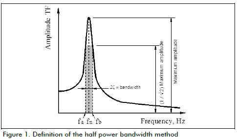
Both the half power bandwidth and the amplitude fitting (Rinawi and Clough, 1992) methods use DTF shape to evaluate natural vibration frequencies and the damping involved in measured response (Figure 1). However, when TF amplitude is more accurate than phase, results' reliability becomes improved by using the amplitude fitting method. The theoretical single degree of freedom system DTF is fitted to the experimental shape of a similar DTF in this approach. According to Rinawi and Clough, (1992), a well-separated peak in the DTF can be approximated by the response of a single mode n as:
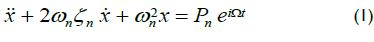
where ωn and ζn are angular frequency and damping for particu-lar mode n, and Pn is the participation factor for the mode under consideration. At a given input angular frequency Ωk, the steady state amplitude of the response x is given by:
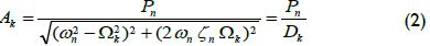
By using arithmetic simplifications, for a set of frequencies Ωk, equation (2) can be written as:
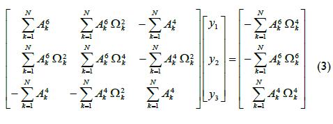
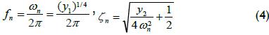
Once equation (3) has been solved, natural vibration frequency (ƒn) and damping factor (ζn) can be computed from:
Experimental programme
The three-dimensional prototype was a two-story house having 100-mm thick, 2,400-mm high concrete walls and 15 MPa speci-fied concrete compressive strength (ƒc'). Shake table tests are currently the most effective method for assessing the experimental performance of specimens subjected to seismic action. The experimental programme thus involved a shake table test of six thin concrete walls. The variables studied were the type of concrete (normal and lightweight), the web steel shear ratio (0.125% and 0.25%), the type of web shear reinforcement (de-formed bars and welded wire meshes) and the effect of openings (doors and windows).
Geometry, reinforcement layout and materials
Due to limitations in shake table payload capacity, lightly-reduced and isolated wall models were built (i.e. geometry scale factor, SL=1.25). The simple law of similarity was chosen because specimen size was very similar to that of isolated walls in the prototype (80% prototype size). The models were built with the same material as the prototype in this type of similarity (i.e. material properties were not changed) and only the models' dimensions were altered. Table 1 shows the main simple law of similarity scale factors.
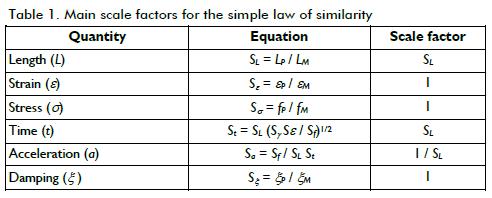
Table 2 gives the specimens' characteristics. The specimens' height-to-length one-to-four ratio was equal to one (hw/lw=1). Door and window opening configuration was typical of the pro-totype house for last two specimens. Three specimens' geometry and reinforcement layout are shown in Figure 2. Nominal web steel ratio corresponded to the minimum web steel ratio prescribed by ACI-318 building code (2011) for MCN100, MCL100 and MVN100 walls, and deformed bars were used to provide web shear reinforcement. Nominal web steel ratio was approxi-mately 50% of the minimum web steel ratio prescribed by ACI-318 for MCN50m, MCL50m and MVN50m walls, and welded-wire mesh was used to provide web shear reinforcement. Longitudinal reinforcement at the boundary elements was purposely designed and detailed to prevent flexural failure prior to achieving shear strength.
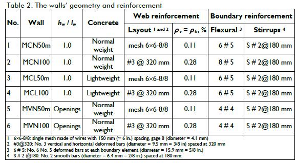
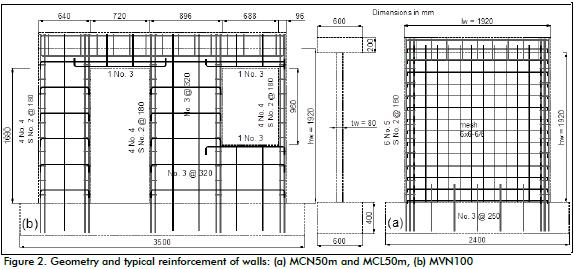
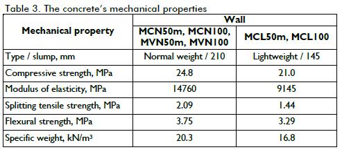
Table 3 shows the mean value of measured mechanical proper-ties of concrete. These properties were measured at the time of wall testing.
Seismic demand
Three types of record were used for testing walls: low-frequency, forced vibration and seismic excitation (Table 4). Tests started with sine-curve and ramp (RM) signals which were used to evaluate the mass-carrying system friction level during low-velocity excitation. Both sine (SN) and ramp (RM) signals having 0.5 Hz and 0.02 Hz frequencies were used. A random acceleration signal (white noise (WN)) at 10 cm/s2 (0.01 g) RMS at the beginning and the end of the seismic tests was used to identify the main dynamic properties.
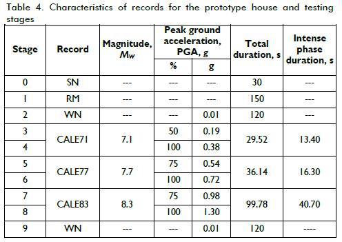
Specimens were subjected to three earthquake hazard levels to study wall performance under different limit states, from onset of cracking to collapse, using both natural and numerically-simulated acceleration records. An earthquake record from an epicentre region in Mexi-co (MW 7.1, CALE71) was used for seismic demand in elastic limit state. This record was considered a Green's function for numerically simulating larger-magnitude events. Two earthquakes having 7.7 (CALE77) and 8.3 (CALE83) MW magnitude were numerically simulated for strength and ultimate limit states, respectively. Table 4 gives the main characteristics of records for prototype house and testing stages. According to the simple law of similarity, acceleration and time scale factors were applied to these records for testing models (Sa = 0.80 and St = 1.25, Table 1). Models were tested under progressively more severe earthquake actions by scaling up the value of peak acceleration as the reference factor, until the final damage stage was attained. The results of both forced vibration and seismic excitation tests were used for identifying the wall speci-mens' vibration period and damping factor.
Dynamic similarity
For adequately extrapolating the specimens' response to a prototype's response, isolated wall models were designed considering a prototype house's fundamental vibration period. Mathematical models were developed and calibrated through ambient vibration testing to establish such dynamic characteristics. Hence, a two-story house's fundamental vibration period was estimated as being 0.12 s (Carrillo, 2011). Taking the simple law of similarity scale factors into account (St = 1.25, Table 1), isolated wall models were designed to achieve an initial in-plane vibration period close to 0.10 s. The dynamic weight (mass × gravity acceleration) used for achieving the desired design period thus varied from 195 kN to 238 kN.
Test setup
If the dynamic weight were to rest at the top of the models, it significantly increased the weight acting on the table platform and thus made controlling movements more complex and difficult. An external device for transmitting inertia forces to the models using a mass-carrying sliding system was thus used to avoid the risk of models' lateral instability to remove noise in recorded signals and keep test specimens' weight within table payload. The device allowed horizontally guiding mass within a fixed support-ing structure installed outside the shake table (Carrillo and Alco-cer, 2011). Additional mass blocks (dynamic weight) were placed in a steel box which, in turn, was supported by a very low friction linear motion guide system (LMGS) (Figure 3).
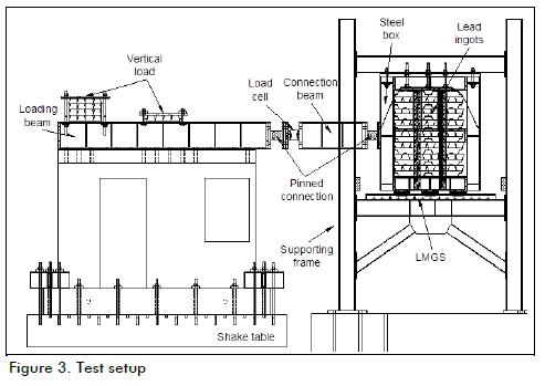
A 0.25 MPa axial compressive stress was uniformly applied to the walls and was kept constant during testing. This value was 2% of the concrete's nominal compressive strength. Finite element models of two-story houses were used for determining the average axial stress at service loads on the housing prototype's first storey walls (Carrillo, 2011). The axial load was exerted through the weight of the load and connection beams, and lead ingots bolted to the load beam (Figure 3). Although lead ingots resulted in a triangular load distribution, adding the weight of the connection beam provided uniform axial load distribution on the walls.
Failure modes
Prior to testing, all walls exhibited early-age cracking, mainly at the corners of the wall web. Crack width was smaller than 0.05 mm; such cracks may have been caused by concrete shrinkage. According to these cracks' location and slope at wall surface, early-age cracking may have been triggered by steel constraint of longitudinal reinforcement at the boundary elements. In any case, these cracks only affected initial wall stiffness (Carrillo, 2011).
Web reinforced walls using welded-wire mesh at 50% of the minimum code-prescribed web steel ratio had diagonal tension (DT) failure. Failure mode was brittle and governed by web inclined cracking at around 45°, plastic yielding of most of web shear reinforcement and subsequent wire breaking. By contrast, walls reinforced by using deformed bars and having the minimum web steel ratio exhibited a mixed failure mode, where diagonal tension and diagonal compression (DT-DC) were observed; yielding of most web steel reinforcement and noticeable web crushing of concrete was observed in these walls.
Results and Discussion
The mass-carrying load system simplified the test setup. Howev-er, when a sliding system was used, the models' natural vibration period prior to and after each test could not be estimated using hammer impact testing (or similar methods), since any small displacement demand on the models became almost instantane-ously damped to zero (Carrillo et al., 2012a). The specimens' damping factors were thus identified by using DTF amplitude fitting.
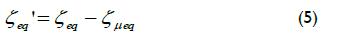
According to Chopra (2001), the natural vibration period for a system having Coulomb damping is the same as a system with no damping. Hence, the device used for testing had no effect on the specimens' vibration period. However, for calculating the specimens' effective equivalent viscous damping ratio (ζeq'), it was necessary to subtract the damping generated in the LMGS (ζµeq), from a specimen's equivalent viscous damping ratio (ζeq):
Damping factors generated in the LMGS during shake table test-ing were calculated in line with Carrillo and Alcocer (2011). The highest damping value added by LMGS was 0.20% (i.e. 2% of the damping in the specimens' response). It can thus be concluded that the mass-carrying load system LMGS did not add a significant amount of damping to a specimen's response.
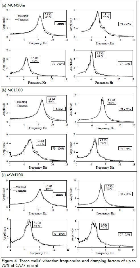
Natural vibration frequencies
During excitation of both white noise signals and earthquake records, DTFs were estimated as the ratio of the spectral amplitude of acceleration recorded at the top of specimens (loading beam) to that recorded at the base (shake table). Figure 4 shows ratios of measured spectral amplitude for three walls of up to 75% of CA77 earthquake records; DTFs for all the specimens may be found elsewhere (Carrillo, 2010). Acceleration records were measured during white noise excitation during the initial testing stage. The procedure proposed by Rinawi and Clough (1992) was followed for identifying the frequency and damping factor from curves in Figure 4 (thus showing both measured and computed DTFs). Natural vibration frequencies and effective damping factors are included in the Figures.
Damping factors
The change of effective damping factors with specimens' vibra-tions period is shown in Figure 5. The period was calculated as the vibration frequency's inverse value. According to the simple law of similarity, the damping scale factor (S = 1, Table 1) did not need to be applied to the results of walls tested through shake table excitation. However, vibration periods became in-creased by 1.25 because of period scale factor (ST = 1.25). The fitted curve had very good agreement with test data, as can be observed from the correlation coefficient, r.
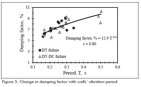
Figure 5 shows that the damping factor became slightly increased with vibration period; for example, damping factors associated with initial loading stage were roughly 6%, but increased to 9% on failure. Damping factors measured during the initial stage were related to very small amplitudes applied during white noise excitation. It should be also noted that the damping factors in Figure 5 were not related to total damping of low-rise reinforced concrete wall housing. Total damping of a concrete house would depend on structural system damping and non-structural elements (if present), as well as friction between different elements (Aristizabal-Ochoa, 1983). However, a starting point was to estimate structural element damping because a house's total damping may be similar or slightly higher than that of structural elements. Figure 5 shows that damping factors associated with the "undamaged" stage were close to 6% and thus, total concrete house damping would be similar or slightly higher than this value.
After concrete cracking, measured damping was primarily credited to steel reinforcement yielding (of deformed bars) or plasticity (of welded-wire mesh), as well as the energy dissipated by friction between crack surfaces and concrete crushing. Figure 5 shows that the damping factors of walls suffering DT failure were roughly 8% higher than those of walls having a mixed DT-DC failure mode. For instance, when the failure mode was governed by concrete crushing (i.e. DT-DC failure), hysteresis loop pinching became more significant (Carrillo and Alcocer, 2012b) and, thus, damping factors were smaller than those of failures governed by web steel reinforcement yielding/plasticity (walls failing through diagonal tension).
Conclusions
During the last few years, constructing low-cost housing made of concrete walls has noticeably increased in some Latin-American countries. This study has experimentally assessed the damping factor usually assumed for dynamic analysis of concrete houses. The amplitude fitting method provided significant advantages in estimating the damping factors of low-rise concrete walls subjected to characteristic seismic excitation because both vibration frequency and damping factor were directly computed from measured DTF values. It was thus not necessary to carry out free vibration tests or compute the dissipated energy involved in each hysteretic loop during seismic excitation.
Assessing the measured response revealed that damping factors associated with the "undamaged" stage of low-rise concrete walls was close to 6%. The total damping of a concrete house would be at least equal to that value and thus the 5% damping factor commonly used for lineal dynamic analysis may be considered suitable for the code-based seismic design of concrete housing. The equation proposed in Figure 5 proved a useful tool for estimating the damping factor associated with a concrete house's particular vibration period value.
Acknowledgments
The authors gratefully acknowledge the financial support provided by Grupo CEMEX and extensive assistance in experimental testing provided by staff and students at UNAM's Instituto de Ingeniería Shake Table Laboratory.
References
American Concrete Institute (ACI), Building code requirements for structural concrete (ACI 318-11) and commentary, Farmington Hills, MI, 2011. [ Links ]
Aristizabal-Ochoa, J., Cracking and shear effects on structural walls. Journal of Structural Engineering - ASCE, Vol. 109, No. 5, 1983, pp. 1267-1277. [ Links ]
Carrillo J., Evaluation of shear behavior of concrete walls using dynamic tests, PhD thesis, Universidad Nacional Autónoma de México, UNAM, 2011 (in Spanish). [ Links ]
Carrillo, J., Gonzalez, G., LLano, L., Evaluation of mass-carrying systems for shaking table experiments., DYNA Journal, Vol. 79, No. 176, 2012a. [ Links ]
Carrillo, J., Alcocer, S., Experimental investigation on dynamic and quasi-static behavior of low-rise reinforced concrete walls., Journal of Earthquake Engineering and Structural Dynamics, DOI: 10.1002/eqe.2234, 2012b. [ Links ]
Carrillo, J., Alcocer, S., Improved external device for a mass-carrying sliding system for shaking table testing., Journal of Earthquake Engineering and Structural Dynamics, Vol. 40, No. 4, 2011, pp. 393-411. [ Links ]
Chopra, A., Dynamics of structures - Theory and applications to earthquake engineering., Segunda Edición, Editorial Prentice-Hall, New Jersey, 2001. [ Links ]
Rinawi, A., Clough, R., Improved amplitude fitting for frequency and damping estimation., 10th International Modal Analysis Conference - Society for Experimental Mechanics, Bethel, CT, 1992, pp. 893-898.Church, R., Geographical information systems and location science., Computers & Operations Research, Vol. 29, No. 6, Jun., 2002, pp. 541-562. [ Links ]
