


Services on Demand
Journal
Article
 English (pdf)
 Article in xml format
 Article references
 Send this article by e-mail
Indicators
-
 Cited by SciELO
 -
 Access statistics
Related links
-
 Cited by Google
 -
 Similars in
SciELO
Similars in
SciELO -
 Similars in Google
Share

 Permalink
Ingeniería e Investigación
Print version ISSN 0120-5609
Ing. Investig. vol.32 no.3 Bogotá Dec. 2012
Manoeuvre test simulation of a teleoperated robot designed for flow measurement in natural water bodies
Simulación de pruebas de maniobra para un robot teleoperado diseñado para medir caudales en cuerpos de agua naturales
C. E. Díaz-Gutiérrez1, J. A. Segovia-de-los-Ríos2, M. P. Garduño-Gaffare3, J. S. Benítez-Read4
1 Carlos Eduardo Díaz Gutiérrez. Affiliation: Universidad Tecnológica de Toluca, México. DSc in Electric Engineering, Universidad Tecnológica de Toluca, México. E-mail: carlos_eduardo_dg@yahoo.com.mx
2 Jose Armando Segovia de los Ríos. Affiliation: Instituto Nacional de Investigaciones Nucleares, México. DSc in Systems Control, Université de Technologie de Compiegne, France. MSc in Sciences, Instituto Tecnológico de La Laguna, México. Electromechanic Engineer, Instituto Tecnológico de Toluca, Mexico. E-mail: armando.segovia@inin.gob.mx
3 Mayra P. Garduño Gaffare. Affiliation: Instituto Tecnológico de Toluca, Mexico. DSc in Computational Sciences, MSc in Computational Sciences, Instituto Tecnológico de Toluca, Mexico. E-mail: mayrag2001@hotmail.com
4 Jorge S. Benítez Read. Affiliation: Instituto Nacional de Investigaciones Nucleares, México. DSc in Electronic Engineering, University of Nuevo México, EEUU. MSc in Engineering, University of Toronto, Canada. Industrial Engineer in Electronics, Instituto tecnológico de Chihuahua , Mexico. E-mail: Jorge.benitez@inin.gob.mx
How to cite: C. E. Díaz-Gutiérrez, J. A. Segovia-de-los-Ríos, M. P. Garduño-Gaffare, J. S. Benítez-Read. (2012). Manoeuvre test simulation of a teleoperated robot designed for flow measurement in natural water bodies. Ingeniería e Investigación. Vol. 32, No. 3. December 2012, pp. 66-70.
ABSTRACT
This article describes the simulation results of manoeuvring operations used in ships, but applied to an SA-1 teleoperated aquatic robot. The SA-1 is a type of robot designed for flow measurement in natural water bodies (rivers, lakes). A robot's dynamic stability and course stability must be guaranteed due to the different tasks assigned to it. These features can be demonstrated through the pull-out manoeuvre, the Dieudonné spiral manoeuvre, modified Kempf manoeuvre and turning circle manoeuvre. System behaviour when using such manoeuvres can be used to propose a better control system for improving robot performance or modify system design.
Keywords: Teleoperated-aquatic-robot, simulation, mathematical-model, ship-manoeuvre, PWM-function.
RESUMEN
En este artículo se describe el resultado de los ensayos de simulación de maniobras que son empleadas en buques aplicadas en un robot acuático teleoperado llamado SA-1 (sistema de aforo 1) con la finalidad de determinar su estabilidad y capacidad de ma-niobra. El SA-1 es un robot diseñado para la medición de flujo en cuerpos de agua naturales (ríos, lagos, etc.), entre otras tareas importantes. Debido a las actividades que el robot tiene que realizar es importante que este sistema presente tanto estabilidad dinámica como de rumbo, capacidades que pueden ser determinadas mediante la maniobra de salida (conocida como pull-out), la maniobra de Dieudonné, la maniobra de Kempf revisada y la maniobra de giro (turning circle). Con los resultados de estas maniobras es posible proponer un sistema de control que mejore la actuación del robot o modificar el diseño del sistema.
Palabras clave: Robot-acuático-teleoperado, simulación, modelos-matemáticos, maniobras-de-barcos, función de PWM.
Received: August 29th 2011 Accepted: November 9th 2012
Introduction
A ship must be able to maintain its course in any water body, safely manoeuvre in ports and restricted passage canals and stop within a predefined distance. Such minimum capability is required in terms of ample load range, high or moderate speed, narrow water passages or any other condition determined by the type of manoeuvring task.
A series of standard tests related to such capacity (known as the manoeuvring tests) can determine dynamic stability, course stability, recovery capacity and evolution capacity. Test results provide insight for design engineers to either propose control systems or redesign parts of an aquatic structure to improve system performance (Velasco et al., 2004).
The SA-1 is a teleoperated aquatic robot designed to measure flow rates in natural water bodies; Díaz et al., (2012) have described how the SA-1 performs. Given the harsh environmental conditions in which such robot operates, it is highly recommended to simulate the above mentioned standard tests before a system be constructed and brought to a real water body.
Mathematical models have been used for simulating the manoeuvring tests. The results of four such tests normally used for ship testing are reported here:
- Pull-out manoeuvre used to determine dynamic stability (Marí, 1995);
- Dieudonné manoeuvre used to determine course stability (Marí, 1995);
- Modified Kempf manoeuvre useful in determining recovery capacity (Marí, 1995); and
- Turning circle manoeuvre (Marí, 1995; Velasco et al., 2004) used to determine a robot's evolution capacity.
Simulink (Mathworks, Inc) was used to simulate each standard test and a Microsoft videogame wheel (sidewinder wheel) was used as a ship's rudder.
Development
Figure 1 shows the SA-1 system which was designed to carry all the equipment needed for gauging capacity or flow measurement in natural water. This water platform consisted of three main parts: two outriggers and a central housing housing computer systems, power electronics, measuring instruments and the power source.
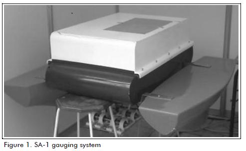
The SA-1 was 1 m long, 1 m wide and 0.60 m high.
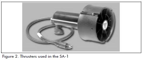
The SA-1 was moved by using two electric thrusters (shown in Figure 2); these thrusters provided 80 W power each, requiring a 4.25 A current at 19 V and each provided a 28.4N thrust.
The SA-1 had a PC-104 format PCM-9375 computer and a single board computer (SBC), called Servopod, based on a digital signal processor (Motorola DSP56F807) governing the propellers, engine measurement system, power circuits, the measurement system and communication between the SA-1 and a computer located on land (i.e. the operating console).
Mathematical models
The mathematical models used in the simulations are now de-scribed below.
Kinematic model
Because the SA-1 is a differential locomotion robot, an analogy with terrestrial differential traction vehicles was made to determine the kinematic model; however, in this particular case, instead of considering the radius of the wheels, the propellers' pitch (the step of the blades) was considered. The kinematic model equations were then:
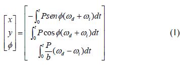
x being the position on the x axis,
y the position of the y axis,
θ the robot heading,
P the propellers' pitch,
ωd and ωi angular speed of the left and right thrusters, respec-tively, and
t was time.
Dynamic model
The SA-1 dynamic model was based on the second order Nomo-to model (Velasco et al., 2004; Yaw Tzeng et al., 2008; Ayza et al., 1980; Amerongen, 2005; Fossen, 1994). The equation for yaw rate was thus:
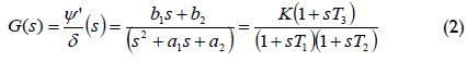
with K = 0.02012, T1 = 1.233 s, T2 = 8 s, T3 = 7.977 s, T = 1.256 s, ψ' was the yaw rate and the rate of change for the wheel, in this case (according to the robot's design) it was the difference in thruster speed (note δ = Φ in the kinematic model). The values shown in (2) referred to hydrodynamic coefficients which were calculated by empirical equations following the pro-cedure proposed by Fossen (1994) and VanZwieten (2003).
The transverse speed equation was (Velasco et al., 2004; Fossen, 1994):
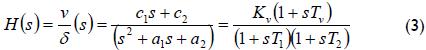
In this case, Kv = 0.06181 and Tv = 7.757 s. The procedure for calculating the values shown in (3) was performed similarly, as described by the aforementioned authors.
Thruster model
The thrusters were constructed based on direct current motors so that the transfer function used for this type of system was (Baño, 2003):
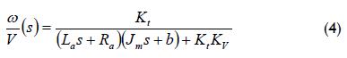
where:
Kt, was the motor torque constant in N-m/A, La, the inductance in H, Ra, armature resistance in Ω, Jm the moment of motor inertia in kg-m2, b the viscous friction coefficient in N-m/rad/s and Kv speed constant V/rad/s.
Having determined the required values, according to the methodology proposed by Baño (Baño, 2003), the thrusters' transfer function was:
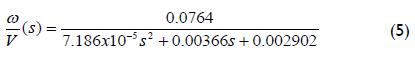
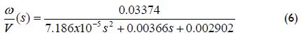
The result of (5) had to be multiplied by the thruster's efficiency coefficient, o= 44.16%= 0.4416, yielding the equation as:
Pulse width modulation (PWM)
Pulse width modulation (PWM) is the most commonly used technique for controlling direct current motor speed, obtained by switching applied power; this produces the effect of a variable voltage source. Such variation allows precise and smooth control of direct current motor speed and also does not dissipate energy unnecessarily. There is a linear relationship between power device ON time and PWM circuit output voltage, obtained by the relationship represented by equation 7 (Segovia, 2003):
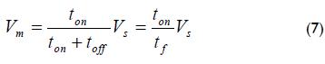
where Vs represented power source voltage, ton power pulse duration and toff its off time. The sum ton + toff represented the period the PWM control signal lasted. As can be readily seen in equation 7, effective voltage Vm applied to a motor was a linear proportion to the period of ignition time.
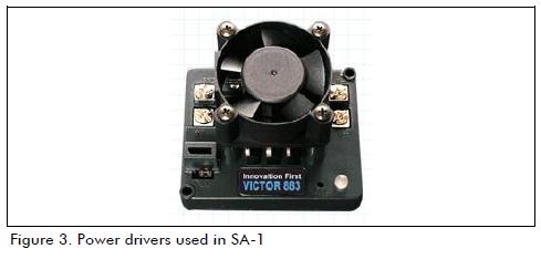
However, for some kinds of switching of power devices, the function may not exhibit this behaviour, this being the case in drivers used to control SA-1 motors which consist of 4 power amplifiers (Figure 3). These amplifiers operated in a 6 to 30 V voltage range, at maximum 60 A current.
Accordingly, it was necessary to determine a function which related input signal duration to the power circuit with the voltage actually obtained. An equation representing this relationship was determined experimentally and given by the following expression:
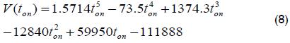
In this case, V(ton) was the thrusters' voltage and ton was the pulse width value generated by the Servopod.
Rudder machine
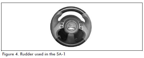
The rudder machine was responsible for rotating the SA-1 according to the commands sent by the helmsman. In naval issues, the rudder is the device used to direct flow and cause a turning or pushing effect (Tupper, 2002). In the particular case of SA-1, the rudder was used by the pilot to cause a difference in propeller speed. The device used as a rudder for performing the simulations is shown in Figure 4; it was a Microsoft sidewinder wheel which is usually used in video games.
The rudder also had a direction indicator (Figure 5) which aimed to show the pilot the angle that the robot was spinning at. The wheel operated in a range of: -30º 30º.
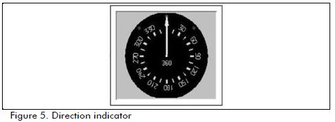
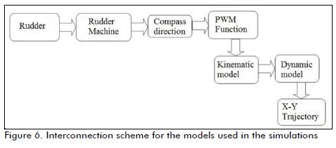
Figure 6 shows the interconnection of the models used in the simulations. The simulink model has already been explained by Diaz (Díaz et al., 2011):
Description of manoeuvring tests
A ship's manoeuvrability can be defined as the percentage of effectiveness with which the helmsman can maintain or vary the bow of the ship at will, to achieve a certain position in its imme-diate environment (Marí, 1995; Triantafyllou and Hover, 2003).
This definition contains two capacities:
Manoeuvre capacity, characteristic of keeping the bow of the boat under control. The curves used to determine the degree of a boat's steering capability, referring to their significant aspects would be: output curve or pullout curve, Dieudonné curves, Bech's reverse and rudder histograms.
Evolution capacity is related to the capacity of varying the heading of a vehicle/ship with maximum efficiency. It can be defined as a boat's response to the joint action of the machine and the rudder for a change of course and carrying out a planned order of approach, departure, study of behaviour at different magnitudes regarding the incidence of internal and external agents applied, etc. The most representative curve is the curve known as the turning circle.
Texts published by Mari (Mari, 1995), Triantafyllou and Hover (Triantafyllou and Hover, 2003) and Velasco (Velasco et al., 2004) have described how manoeuvre tests are performed.
Simulation results
The port side pull-out manoeuvre results are shown in Figure 7(a), whereas port side yaw speed compared to time is shown in Figure 7(b).
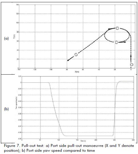
Figure 7(b) shows that yaw speed was not equal to zero when setting the rudder amidships; this was due to the fact that, even though the input signal to both propeller engines' power amplifi-ers was the same, the output voltage of one of them was slightly greater, causing a small system drift. Yaw speed approached zero as the test progressed. The same result was obtained for the starboard pull-out test.
Figure 8(a) shows the port side Dieudonné test SA-1 trajectory; Figure 8(b) shows the plot of port side yaw speed compared to rudder angle.
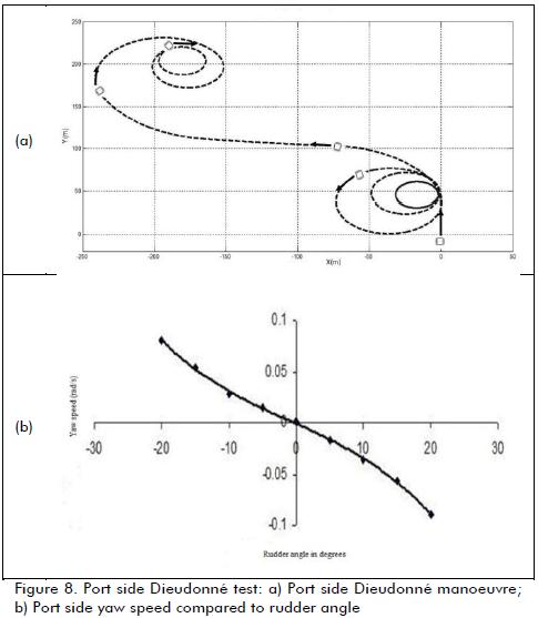
Notice, in Figure 8(b), that the plot crossed the origin. This meant that a zero port side yaw speed was attained when setting the rudder amidships. This, in turn, indicated good system course stability. Similar results were obtained for the starboard Dieu-donné test.
Figure 9 gives the results of simulating the modified Kempf test applied to the port side.
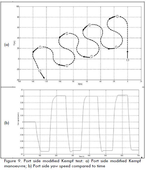
According to the graphical results (shown in Figure 9) corresponding to this test, the SA-1 responded suitably to changes in rudder direction which, in turn, pointed to good recovery capacity. Similar results were obtained when carrying out the star-board Kempf test.
The result of the port side turning circle test is shown in Figure 10.
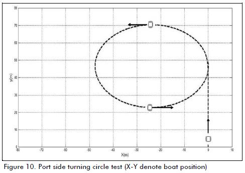
Similar results were obtained for the starboard turning circle test.
Conclusions
Based on the results obtained for the different manoeuvring tests, it can be concluded that the aquatic robot model behaved suitably.
Moreover, the SA-1 system was controllable which meant that it could be accurately positioned at any desired point on the water body according to the helmsman's commands. The simulations also showed some desirable system features such as good dy-namic stability, course stability, recovery capacity and evolution capacity. Considering the SA-1 characteristics, control schemes can be simulated and validated before physically implementing them.
Acknowledgements
The authors wish to acknowledge the financing provided by the Colombian Ministry of Higher Technological Public Education (Dirección General de Educación Superior Tecnológica) for this project (financial support agreement DGEST 906.08-P). Carlos Eduardo Díaz Gutiérrez would like to thank the National Council for Science and Technology (CONACYT) for financial support provided through scholarship 229234. The assistance of David Contreras and personnel from the Mexican Nuclear Research Institute's Mechanical Workshop (ININ) in machining some of the SA-1's mechanical components is highly appreciated.
References
Amerongen J. V. Adaptive steering of ships. A model reference approach to improved maneuvering and economical course keeping. PhD Philosophy thesis, Delft University of Technology, 2005. [ Links ]
Ayza J., López J., Quevedo J. Modelización de la dinámica de un buque. Qüestió. Vol. 4. No. 3, 1980, pp. 137-146. [ Links ]
Fossen T. I. Guidance and control of ocean vehicles. London, England, John Wiley and Sons Ltd, 1994. pp. 5-48 [ Links ]
Marí S. R. Maniobra de los buques. Madrid, Spain, Edicions UPC., 1995. pp. 63-122. [ Links ]
Segovia A., Zapata R., Lepinay P. Control PWM: Algunas Consideraciones de Diseño, ELECTRO 2003, Chihuahua, Chih. , Octubre, 2003, pp. 17-22. [ Links ]
Triantafyllou S. M., Hover S. F. Maneuvering and control of ocean Vehicles. Department of Ocean Engineering. Massachusetts Institute of Technology. Cambridge, Massachusetts USA, 2003. pp. 152-160. [ Links ]
Tupper E. Introduction to naval architecture. London, England, Ed. Butterworth Heineman Publications, 2002. pp 209-252. [ Links ]
VanZwieten T. S. Dynamic simulation and control of an autonomous surface vehicle. MSc thesis, Atlantic University, Boca Raton, Florida, USA, 2003. [ Links ]
Velasco J. F., Rueda R. M. T., Lopez G. E., Moyano P. E. Mathematical model for govern control of ships. XXV Jornadas de Automática. Ciudad Real, España, 2004. [ Links ]
Yaw Tzeng C., Fen Chen J. Fundamental properties of linear ship steering dynamic models. Journal of Marine Science and Technology. Vol. 7, No. 2, 2008. pp. 79-88. [ Links ]
