


Services on Demand
Journal
Article
 English (pdf)
 Article in xml format
 Article references
 Send this article by e-mail
Indicators
-
 Cited by SciELO
 -
 Access statistics
Related links
-
 Cited by Google
 -
 Similars in
SciELO
Similars in
SciELO -
 Similars in Google
Share

 Permalink
Ingeniería e Investigación
Print version ISSN 0120-5609
Ing. Investig. vol.33 no.1 Bogotá Jan./Apr. 2013
E. Gomez-Luna1, G. Aponte2, W. Herrera3 and J. Pleite4
1 Eduardo Gómez-Luna. Ingeniero Eléctrico, Universidad del Valle, Colombia. Affiliation: Universidad del Valle, Colombia. E-mail: eduardo.gomez@correounivalle.edu.co
2 Guillermo Aponte. PhD in Ingeniería con énfasis en Ingeniería Eléctrica, Universidad del Valle, Colombia. Affiliation: Universidad del Valle, Colombia. E-mail: guillermo.aponte@correounivalle.edu.co
3 Wilder Herrera. Ingeniero Eléctrico, Universidad del Valle, Colombia. Affiliation: Universidad del Valle, Colombia. E-mail: wilderh2@hotmail.com
4 Jorge Pleite Guerra. PhD en Ingeniería con énfasis en Ingeniería eléctrica, Universidad Carlos III de Madrid, Spain. Affiliation: Universidad Carlos III de Madrid, Spain. E-mail: pleite@ing.uc3m.es
How to cite: Gomez-Luna, E., Aponte, G., Herrera, W., Pleite, J., Experimentally obtaining on-line FRA in transformers by injecting controlled pulses., Ingeniería e Investigación. Vol. 33, No. 1. April 2013, pp. 41-45.
ABSTRACT
Transformer monitoring based on the operating condition (on-line test) has boomed in recent years because it allows early detection of risk situations or limitations regarding use to make appropriate decisions before a failure occurs. Frequency response analysis (FRA) is one of the most heavily researched techniques for on-line development; it is based on obtaining a transformer's frequency response (admittance, impedance or transfer function) in a given bandwidth. This paper presents an experimental method for obtaining the frequency response with the transformer in service by injecting controlled pulses of the voltage signal using an external electronic circuit. Once the voltage and current signals had been recorded, the wavelet transform was used via multi-resolution analysis (MRA) for filtering. This led to results being obtained without noise interference from the electrical system. The transfer function was obtained in terms of impedance, using the fast Fourier transform (FFT). The proposed method represented an alternative in solving some problems arising from the on-line FRA technique such as filtering and results' repeatability. The tests involved a 5-kVA 1150/345 V three-phase transformer and a 3-kVA, 7620/240 V single-phase transformer in the Universidad del Valle's High Voltage Laboratory.
Keywords: On-line FRA, on-load FRA, Fourier transform, MRA analysis, filtering, transformer, multi-resolution analysis.
RESUMEN
El monitoreo en transformadores basado en la condición de operación (pruebas en línea) ha tenido un gran auge en los últimos años debido a que facilita detectar oportunamente situaciones de riesgo o limitaciones de utilidad que permita tomar decisiones oportunas, antes de que ocurra una falla. Una de las técnicas en la cual se viene investigando con fuerza para el desarrollo en línea es el análisis de la respuesta en frecuencia (FRA), la cual se basa en obtener la respuesta en frecuencia (admitancia, impedancia, o función de transferencia) del transformador en un ancho de banda determinado. El siguiente artículo presenta un método experimental para obtener la respuesta en frecuencia con el transformador en servicio, por medio de la inyección de pulsos controlados sobre la señal de voltaje, usando un circuito electrónico externo. Una vez registradas las señales de voltaje y corriente, se usó la transformada Wavelet mediante el análisis multirresolución (MRA) para el filtrado, lo que permitió obtener resultados sin problemas de ruido del sistema eléctrico; luego se obtuvo la función de transferencia en términos de la impedancia usando la transformada rápida de Fourier (FFT). De acuerdo con los resultados obtenidos, el método propuesto es una alternativa para dar solución a algunos problemas que se han presentado en la técnica FRA en línea hasta el momento, tales como el filtrado y la repetitividad en los resultados. Las pruebas fueron realizadas sobre un transformador trifásico de 5 kVA, 1150/345 V y un transformador monofásico de 3 kVA, 7620/240 V, en el Laboratorio de Alta tensión de la Universidad del Valle.
Palabras clave: FRA en línea, FRA on-load, transformada de Fourier, análisis MRA, filtrado, transformador, análisis multirresolución.
Received: February 7th 2013 Accepted: March 15th 2013
Introduction
Frequency response analysis (FRA) is a technique which is used to evaluate the state of transformers; it is used worldwide as a complement and for supporting other diagnostic techniques. This test leads to detecting possible mechanical problems, such as displacement or deformation in the windings or core plates which are quite difficult to locate when using other methods.
Two methods are used for obtaining the frequency response in transformers according to the nature of the input signal. Sweep frequency response analysis (SFRA) consists of injecting a periodic small-signal amplitude (1-20 VRMS) sinusoidal signal and variable frequency in a Hz to MHz bandwidth, applied to one of the terminals. This measures the output signal at another of its terminals to obtain the transformer transference function, defined as the quotient between input and output voltages for all frequency points being measured.
The second method, impulse frequency response analysis (IFRA), uses an impulse-type single non-periodic signal, having a maximum value in the order of hundreds of volts and broad frequency content. It is injected by any of the transformer's accessible terminals as excitation or input signal; the output signal is, likewise, measured at another transformer terminal and the frequency response is thus obtained.
A particular transformer must be taken out of service (off-line) for the FRA test (using the SFRA or IFRA method) which is why FRA with the transformer in service (on-line) is an attractive alternative, as this will permit the transformer to be monitored at all times and reduce the costs associated with performing the test (Leibfried and Feser 1999; Krieg and Napolitano 2000; Feser et al., 2000).
Some work has dealt with testing frequency response with on-line transformers via the impulse technique (IFRA) (Christian et al., 1999; Vandermaar 2001; De Rybel et al., 2010; Gomez-Luna et al., 2012)[7]; however, this has detected that certain aspects must be improved, like recording equipment sampling frequency, filtering noise by the power system and test repetition (Wang 2003). The methods proposed until now for on-line IFRA have been based on pulses randomly generated by manoeuvres or by atmospheric discharges, signals over which there is no control regarding the generated transient (Birlasekaran and Fetherston 1999; René Wimmer 2004; (Coffeen 2003; Coffeen 2007; Coffeen et al., 2009)
This article proposes a new method for on-line IFRA by injecting controlled pulses.
A proposed method for an on-line FRA test on transformers
The proposed on-line IFRA experimental method consisted of three stages (presented in Figure 1).
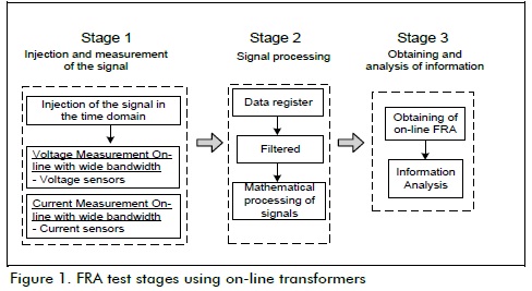
Stage 1 referred to injecting the excitation signal and its measurement along with the output signal. Once the input/output signal had been injected and measured, stage 2 dealt with signal mathematical filtering, recording and processing. Stage 3 consisted of obtaining the FRA curve using mathematical tools.
Stage 1: Injection and signal measurement
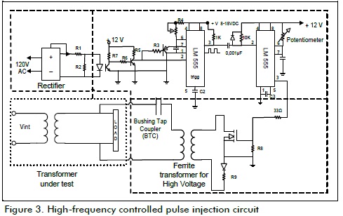
Regarding the injection system, an electronic circuit was specifically designed for injecting controlled pulses on the 60-Hz signal (Figures 2 and 3).
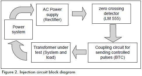
The injection system allowed the amplitude, width and phase of the pulse generated on the 60-Hz wave to be changed, ensuring that it had high spectral content and that there was total control over it.
The electronic circuit consisted of a 60-Hz wave (LM 555) zero crossing detector for controlling the injection moment and a power transistor for generating a low-duration short circuit (µ sec) in series with a ferrite transformer. The pulse was controlled through the transistor's saturation time.
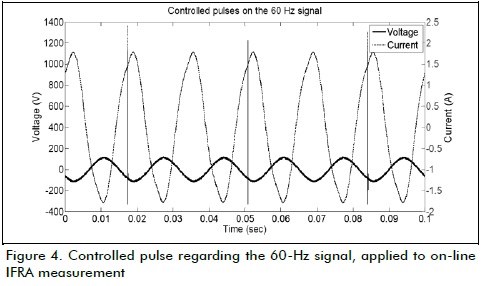
The controlled pulse on the 60-Hz signal was the input signal for the on-line IFRA test; it was sent to the LV side of the transformer being tested through a high-voltage capacitor serving as a low frequency high-pass filter and high frequency low-pass filter. The ferrite transformer isolated the injection circuit of the transformer being tested. Figure 4 shows that the response (pulses in the current signal) was in phase with the injected voltage signal.
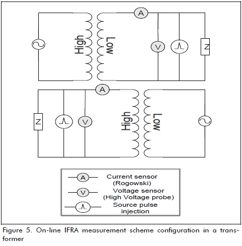
Broad bandwidth sensors, high-voltage sensors for the voltage pulses and Rogowski coils for the current (Figure 5) were used to measure the voltage and current signals thereby allowing transient registry without saturation problems, bearing in mind that the pulses were short duration and had high spectral content.
Stage 2: Signal registry and processing
The controlled pulses on the voltage signals and the response ones in the current signal could be affected by the electrical system's harmonic distortion and background noise which is why suppression signals had to be used for eliminating unwanted signals.
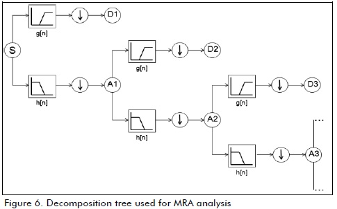
In this case, filtering techniques were used based on discrete wavelet transform (DWT) multi-resolution (MRA). A db4 mother wavelet was selected to eliminate electrical system noise; it was used to filter the electrical signal (Butler-Purry and Bagriyanik 2003; Zheng, Liu, and Ma 2010). This decomposed low- and high-frequency signals by using high-pass g[n] and low-pass h[n] filters (as indicated in Figure 6: Dn represented high-frequency information and approximations and An the low-frequency information).
MRA analysis of DWT was used to eliminate harmonics; however, in this case, the db10 mother wavelet was used with just the voltage and current transient remaining to be analysed by signal processing and for obtaining the transformer's frequency spectrum.
A PCI-6115 data acquisition card (National Instrument) was used for obtaining the signal registry (voltage-current).
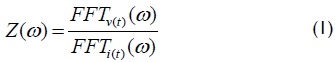
The current and voltage temporal signal spectrum was obtained by mathematical processing of the fast Fourier transform (FFT), calculating the transformer's on-line impedance, Z(w), as quotient between voltage, V(w) and current, I(w) for all frequency components.
Stage 3: Obtaining and analysing information
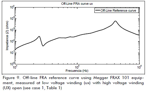
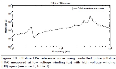
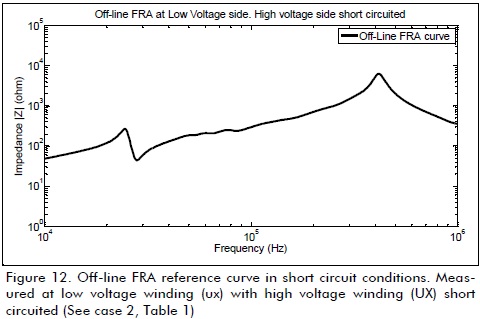
The signal spectra and transformer impedance computed from on-line records, measured while the transformer was energised, were juxtaposed with the corresponding frequency response computed from off-line measurements (SFRA method) using Megger FRAX 101 equipment in the test configurations shown in Table 1. Although the international standard for measuring frequency response (IEC 60076-18 2012) only considers open circuit testing for off-line FRA, short circuit measurements have also been considered in this study.
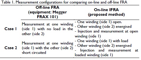
Table 1 was devised for providing a frame of reference to parallel off-line FRA and on-line IFRA methods. Case 1 considered no-load (open circuit) test conditions where the core magnetic circuit effect was predominant. Case 2 concerned full-load situations where winding field leakage became significant. However, the parallel was not complete in case 2, given that the short-circuit test was performed with reduced voltage excitation (no significant core magnetic effects) for off-line FRA, whereas the transformer had nominal voltage excitation for on-line IFRA tests to simulate on-line (in service) conditions.
Experimental validation
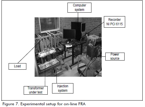
Figure 7 shows the experimental setup used for obtaining a frequency response by injecting controlled pulses (indicating the main on-line test components).
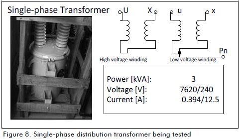
The proposed method was applied using load and no-load conditions on the transformer shown in Figure 8.
Figures 9 to 14 show the corresponding results. The transformer was tested under 100% load, supplying power to a resistive load in the on-line IFRA tests in load conditions.
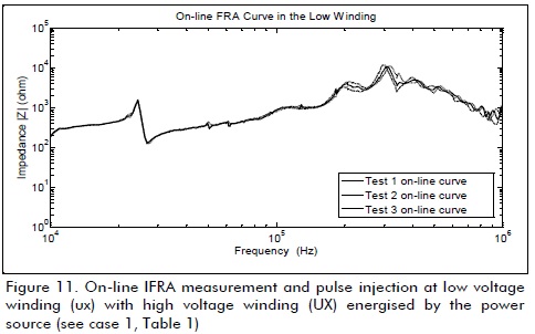
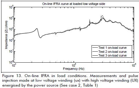
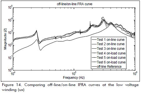
The results revealed a good response in the 10 kHz - 1 MHz range; this may have been because the low-frequency signals (<10 kHz) were greatly affected by the filtering and load system.
The high frequency range on-line curves had resonance which was not present in the off-line curves; this could have been associated with the parasitic capacitance effect of the measurement cables, the load and the whole system connected to the transformer, thereby making the impedance seen unequal. It could also have been attributed to using two different sets of measurement equipment (Megger FRAX 101 for off-line FRA and PCI-6115 recorder for on-line IFRA) and the difference between test conditions. Nevertheless, despite the differences between off-line and on-line curves, monitoring the transformer's physical conditions was based on continuous tracking of changes in the frequency response curve (either off-line or on-line), given that good repetition of the curves was obtained with it, this being one of the basic FRA technique requirements for supporting transformer diagnosis.
So far, all progress in relation to the on-line IFRA method involved using FFT for signal processing; however, by definition, this tool would have been useful for processing stationary signals. Taking that into consideration, transient signal analysis could be hypothetically improved by using wavelet transform for signal processing, given its variable time/frequency resolution (Gomez-Luna et al., 2012; Duarte et al., 2012), thereby forming the basis for future work which the authors are currently working on.
Conclusions
This article has contributed towards obtaining a frequency response in on-line transformers by injecting controlled pulses into the 60-Hz wave.
Although the experimentally proposed method was viable, further signal processing research is needed, given that measurements sometimes become altered by the noise present in a power system, thereby affecting measurement repetition.
The on-line impedance at high frequencies differed from the off-line measurement. This may have been due to the effect of the parasitic capacitance associated with the measurement cables and the load connected to the transformer.
Work on on-line IFRA has involved using the Fourier transform as the mathematical tool to date; the method proposed here has suggested using wavelet transform, given its good response in analysing transient signals.
Acknowledgments
The authors would like to express their gratitude to COLCIENCIAS for the finance received through project 494-2009, as well as Spanish government financing through project DPI2008-05890.
We would also like to thank the Universidad del Valle's High-Voltage Laboratory and the Research Vice-Rector's office for providing funding, facilities and making equipment available for the tests.
References
Birlasekaran, S., Fetherston, F., Off / On-Line FRA Condition Monitoring Technique For Power Transformer., IEEE power Engineering Review, No. 732, 1999, pp. 54-56. [ Links ]
Butler-purry, K.L., Bagriyanik, M., Characterization of transients in transformers using discrete wavelet transforms., IEEE Transactions on Power Systems, Vol. 18, No. 2, 2003, pp. 648-656. [ Links ]
Christian, J., Feser, K., Sundermann, U., Leibfried, T., Diagnostics of power transformers by using the transfer function method. Conference Publication No. 467, High Voltage Engineering Symposium, 22-27 August 1999. [ Links ]
Coffeen, L., Mcbride, J., Woldemariam, N., Benach, J., A Summary of NEETRAC On-line Frequency Response Analysis ( FRA ) a New EPRI Commercial Prototype FRA Installation at First Energy., NEETRAC and EPRI, EPRI Substation Equipment Maintenance Optimization & Diagnostics Conference, San Antonio, TX, March 2009, pp. 1-24. [ Links ]
Coffeen, L., Cantrelle, D., Mango J., On-Line Monitor Tracks Transformer Health., Transmission & Distribution World, Vol. 59, No. 10, Power & Light, October, 2007, pp. 62. [Online], Available: http://connection.ebscohost.com/c/articles/27325791/on-line-monitor-tracks-transformer-health [ Links ]
Coffeen, L., System and Method for On-Line Impulse Frequency Response Analysis., U. S. Patent, 6549017B2, April 15, 2003. [ Links ]
Duarte, C., Delmar, P., Goossen, K., Barner, K., Gomez-Luna, E., Non-Intrusive Load Monitoring Based on Switching Voltage Transients and Wavelet Transforms., International Workshop Future of Instrumentation (FIIW), October, 2012, pp. 1-4. [ Links ]
De Rybel, T., Singh, A., Pak, P., Marti, J. R., Online Signal Injection Through a Bus-Referenced Current Transformer., IEEE Transactions on Power Delivery, Vol. 25, No. 1, January, 2010, pp. 27-34. [ Links ]
Feser, K., Christian, J., Leibfried, T., Kachler, A., Neumann, C., Sundermann, U., Loppacher, M., The Transfer Function Method for Detection of Winding Displacements on Power Transformers after Transport, Short Circuit or 30 Years of Service., Paris, CIGRE, 2000, pp. 1-13. [ Links ]
Gomez-Luna, E., Aponte, G., Gonzalez-Garcia, C., Pleite, J., Current Status and Future Trends in Frequency-Response Analysis with a Transformer in Service., IEEE Transactions on Power Delivery, December 08, 2012, pp. 1-8. Accepted for publication. DOI: 10.1109/TPWRD.2012.2234141. [ Links ]
Gómez-Luna, E., Silva, D., Aponte, G., Pleite, J., Hinestroza, D., Obtaining the electrical impedance using wavelet transform from the time response., IEEE Power Eng. Lett., Dec. 04, 2012, accepted for publication. DOI: 10.1109/TPWRD.2012.2234942. [ Links ]
IEC 60076-18 International Standard: Power transformers. Part 18: Measurement of Frequency Response International Electrotechnical Commission, Ed. 1, July 2012. [ Links ]
Krieg, T., Napolitano, M., Techniques and experience in on-line transformer condition monitoring and fault diagnosis in ElectraNet SA., Proceedings from the International Conference on Power System Technology, 2000, pp. 1019-1024. [ Links ]
Leibfried, T., Feser, K., Monitoring of power transformers using the transfer function method., IEEE Transactions on Power Delivery, Vol. 14, No. 4, Oct., 1999, pp. 1333-1341. [ Links ]
Vandermaar, A., On-line Frequency Response Analysis System. Development of Specifications., EPRI Project Manager, Technical Progress, Development of Specifications No. 1001942, EPRI, Palo Alto, Canada, December, 2001. [ Links ]
Wimmer, R., Feser, K., Calculation of the transfer function of a power transformer with online measuring data., II International Conference on Advances in Processing, Testing and Applications of Dielectric Materials, September 2004, pp. 1-5. [ Links ]
Wang, M., Winding movement and condition monitoring of power transformers in service., Thesis PhD, University of British Columbia, Department of Electrical and Computer Engineering, 2003. [ Links ]
Zheng, E., Liu, Z. Ma. L., Study on Harmonic Detection Method Based on FFT and Wavelet Transform., 2nd International Conference on Signal Processing Systems, (ICSPS), IEEE, 2010, pp. 1-4. [ Links ]
