


Services on Demand
Journal
Article
 English (pdf)
 Article in xml format
 Article references
 Send this article by e-mail
Indicators
-
 Cited by SciELO
 -
 Access statistics
Related links
-
 Cited by Google
 -
 Similars in
SciELO
Similars in
SciELO -
 Similars in Google
Share

 Permalink
Ingeniería e Investigación
Print version ISSN 0120-5609
Ing. Investig. vol.34 no.1 Bogotá Jan./Apr. 2014
https://doi.org/10.15446/ing.investig.v34n1.40726
http://dx.doi.org/10.15446/ing.investig.v34n1.40726
Strains on steel reinforcement of low-rise concrete walls during shake table tests
Deformaciones del acero de refuerzo, durante ensayos en mesa vibratoria con muros de concreto de baja altura
J. Carrillo1, M. Sánchez-Cruz2 and Á. Viviescas3
1Julian Carrillo. PhD in Structural Engineering. Affiliation: Researcher and Professor, Department of Civil Engineering, Universidad Militar Nueva Granada, UMNG, Colombia.
E-mail: jcarrillo@gmail.com
2Martha Sánchez-Cruz. PhD in Mechanics of Solids and Structures. Affiliation: Professor, Department of Civil Engineering, Pontificia Universidad Javeriana and Universidad Militar Nueva Granada, UMNG, Colombia.
E-mail: marthasanchez@javeriana.edu.co
3Álvaro Viviescas. PhD in Structural Engineering. Affiliation: Researcher and Professor, Department of Civil Engineering, Universidad Industrial de Santander, UIS, Colombia.
E-mail: alvivija@uis.edu.co
How to cite: Carrillo, J., Sánchez-Cruz, M., Viviescas, Á., Strains on steel reinforcements in lowrise concrete walls during shake table tests., Ingeniería e Investigación, Vol. 34, No. 1, April, 2014, pp. 36 – 41.
ABSTRACT
During the last few decades, several advantages of concrete wall housing have been identified when compared with masonry houses located in high hazard seismic zones; for instance, higher lateral stiffness and strength, and higher ductility capacity. Therefore, construction of lowrise housing units using reinforced concrete shear walls has become a preferred choice and consequently, its use has increased considerably in many Latin American countries. The aim of this study is to experimentally assess the strains on steel reinforcement of concrete walls for lowrise housing when subjected to seismic actions. The experimental program was comprised of six concrete wall specimens tested under shake table excitations. An efficiency factor was used to reflect the amount of wall reinforcement at yielding. Trends of measured results were compared with the recommendations proposed by the ACI 318-11 Building Code. Results of this study can be used as a suitable tool to evaluate the contribution of reinforcement to the shear strength and displacement capacity of concrete walls for lowrise housing.
Keywords: concrete wall, lowrise housing, shake table test, steel strain, welded-wire mesh, yielding.
RESUMEN
Durante las últimas décadas se han identificado varias ventajas de las viviendas con muros de concreto, cuando éstas se comparan con viviendas de mampostería localizadas en zonas de amenaza sísmica alta; por ejemplo, mayor rigidez lateral y resistencia y mayor capacidad de ductilidad. Por lo tanto, la construcción de viviendas de baja altura usando muros de cortante con concreto reforzado se ha convertido en una opción preferida y de esta manera, su uso se ha incrementado considerablemente en muchos países de América Latina. El objetivo de este estudio es evaluar experimentalmente las deformaciones del acero de refuerzo de muros de concreto para vivienda de baja altura sometidos a acciones sísmicas. El programa experimental comprendió seis especímenes de muros de concreto ensayados bajo excitaciones en mesa vibratoria. Se utilizó un factor de eficiencia para reflejar la cantidad de refuerzo del muro en fluencia. Las tendencias de los resultados medidos fueron comparadas con las recomendaciones propuestas por el Reglamento de Construcción ACI 318-11. Los resultados de este estudio pueden utilizarse como una herramienta adecuada para evaluar la contribución del refuerzo a la resistencia y al desplazamiento de muros de concreto reforzado para vivienda de baja altura.
Palabras clave: muro de concreto, vivienda de baja altura, ensayo en mesa vibratoria, deformación del acero, malla electrosoldada, fluencia.
Received: November 12th 2013 Accepted: February 24th 2014
Introduction
Over the last decade, construction of lowrise (one- and two-story) housing units using reinforced concrete shear walls has become a preferred choice and thus, its use has increased considerably in many Latin American countries such as Mexico, Peru, Chile and Colombia. There have been several advantages to this structural system identified, in comparison to masonry houses located in high hazard seismic zones; for instance, higher lateral stiffness and strength, and higher ductility capacity.
Because of the large wallto-floor area ratio of these units, one- and twostory high, concrete wall structures are subjected to small demands of lateral displacements and seismic forces. This phenomenon has prompted housing designers to use concrete compressive strengths of 15 to 20 MPa, as well as 100-mm thick walls. Also, in zones having low seismic demands, where design is
controlled by vertical actions, the minimum web shear reinforcement prescribed by ACI 318-11 building code appears to be excessive for controlling diagonal tension cracking. As a result, web steel reinforcement ratios smaller than the minimum ratio prescribed by ACI 318-11 building code and web shear reinforcement made of welded-wire mesh are frequently used.
The aim of this study is to experimentally assess the strains on steel reinforcement of concrete walls for low-rise housing during seismic actions. Outcomes of this study are based on laboratory test results obtained from six concrete wall specimens tested under shake table excitations. Wall properties were those obtained from current design and construction practice found in typical lowrise housing in several Latin American countries. A dense instrumentation layout was designed to acquire data on the local response of steel reinforcement through straingages at selected locations, specifically aimed at evaluating layout of yielding of steel reinforcement.
Experimental program
The experimental program comprised of testing six isolated cantilever walls and included the following variables: wall geometry (solid walls with heighttolength ratio equal to 1.0 and walls with door and window openings), concrete type (normalweight and lightweight), web steel ratio (0.125% and 0.250%) and type of web reinforcement (mildsteel deformed bars and colddrawn weldedwire mesh). Although overall description of the experimental program is presented in the following sections, details can be found described by Carrillo and Alcocer (2012).
Geometry and reinforcement
Due to limitations in the payload capacity of the shake table used in this study, lightly-reduced scale models were designed and built (i.e. geometry scale factor equal to 1.25) for testing. Since the size of the models was almost equal to that of the walls in the prototype, the simple law of similitude was then chosen for scaling specimens, as well as for calculating the prototype response from measured response in the wall models. For this type of simulation, models are built with the same materials as the prototype (i.e. materials' properties are not changed) and only the dimensions of the models are altered. Main characteristics of specimens are shown in Table 1. Thickness, tw, and clear height, hw, of wall specimens were 80 mm and 1920 mm, respectively. Thickness of boundary elements was equal to the thickness of the wall web. Length, lw, of solid walls and walls with openings were 1920 mm and 3040 mm, respectively.
The walls were named using the following labeling system. Take, as an example, "MCN50mD". The letter "M" indicates a wall test (from muro, in Spanish). The second letter indicates the geometry: C = solid wall with heightto-length ratio (hw/lw) equal to 1.0, and V = walls with openings (door and window). The third letter indicates the concrete type: N = normalweight, and L = lightweight. The nominal concrete compressive strength, fc', was 15 MPa. The fourth indicator relates to the web steel reinforcement ratio: 100 = 100% of ρmin (0.25%), and 50 = 50% of ρmin (0.125%). The minimum web steel ratio (ρmin) was that prescribed by the AC 318-11 Building Code, which is similar to that prescribed in the Colombian Code of Earthquake Resistant Construction, NSR-10.
Web reinforcement was placed in a single layer in the middle of the thickness of the walls; the same amount of horizontal and vertical reinforcement was used. Web reinforcement ratios in Table 1 were calculated from design dimensions. The fifth indicator relates to the type of web reinforcement. When deformed bars were used, the letter is omitted. Otherwise, a lower-case letter "m" indicates that welded-wire mesh (made of small-gauge wires) was used.
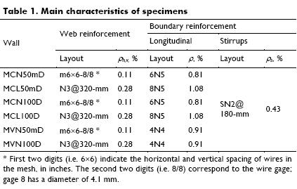
To better understand the strength mechanism that take place during shear failures observed in RC walls for low-rise housing, longitudinal boundary reinforcement in Table 1 was purposely designed to prevent flexural and anchorage failures prior to achieving a shear failure.
Mechanical properties of concrete
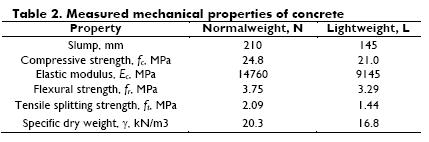
Ready-mixed concrete was used for wall casting. Mean value of the measured mechanical properties of concrete are presented in Table 2. These properties were obtained from cylinder tests at the time of wall testing. Because of the small size of the coarse aggregate and the measured slump, internal consolidation of fresh concrete was not needed. Form vibration was applied through a rubber hammer only.
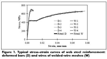
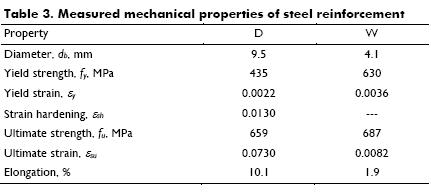
Typical stress-strain behavior of web steel reinforcement, meas-ured from coupon tests, is shown in Figure 1. The fitted stressstrain curve for the two types of web shear reinforcement is included in the figure. In the colddrawn wire reinforcement used in this study, the loading branch between the onset of yielding and the maximum deformation capacity (at fracture) was much shorter than that of mildsteel reinforcement. The behavior of wire rein-forcement was characterized by the fracture of material with a slight increment of strain (see the Elongation row in Table 3).
Type of testing and instrumentation
Wall specimens were subjected to a series of base excitations represented by earthquake records associated to three limit states. An axial compressive stress of 0.25 MPa was applied on top of the walls and was kept constant during testing. This value corresponded to an average axial stress in the first floor walls of a two-story prototype house.
Walls were instrumented internally and externally for measuring the response. Internal instrumentation was designed to acquire data on the local response of steel reinforcement through straingages at selected locations, specifically aimed at evaluating the lay- out of yielding of steel reinforcement. Location of strain gauges used in solid walls and walls with openings are shown in Figures 2 and 3, respectively.
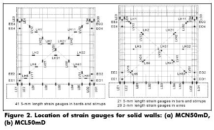
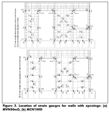
External instrumentation was planned for measuring the global response through displacement, acceleration and load transducers. Also, an optical displacement measurement system with Light Emitting Diodes (LEDs) was used. In the tests, 41 strain-gages and 36 external transducers were used for solid walls, as well as 59 and 64, respectively, for walls with openings.
Definition of yielding
Yielding of steel reinforcement was defined as the manifestation of permanent strains after recording strains higher than yield strain, εy. Values of yield steel strain were those measured from coupon tests of steel reinforcement used for construction of wall models. "Yielding" is clearly defined for reinforcement made of mild steel where an increment of tensile strength is not observed until a well-defined yielding plateau is developed (Fig. 4(b)). In contrast, colddrawn wire reinforcement used in this study did not exhibit a specific yield point, and thus the correct term for welded-wire mesh is "plastic yielding."
Test results and discussion
Wall response was assessed through failure modes, layout of steel strains, identification and progress of yielding as well as the strain in web reinforcement.
Failure modes
Three failure modes were defined for assessing the observed wall behavior: a) when yielding of more than 70% of the web shear reinforcement and no web crushing of concrete was observed, a diagonal tension failure (DT) was defined; b) when yielding of some steel bars or wires and noticeable web crushing and spalling of concrete was observed, a diagonal compression failure (DC) was defined, and, c) when yielding of more than 70% of the web steel reinforcement and noticeable web crushing of concrete was observed, a mixed failure mode (DTDC) was defined. Test results indicated that the contribution of wall sliding to the whole deformation was negligible for all tests (Carrillo and Alcocer, 2012). Therefore, wall sliding at the base was not purposely included.
Walls reinforced with 50% of the minimum code-prescribed web steel reinforcement ratio and welded-wire mesh, exhibited DT failure. Failure mode was governed by web inclined cracking of concrete at approximately 45° and yielding of most of the web shear reinforcement prior to severe strength and stiffness decay. In addition, wire fracture after plastic yielding of web shear rein-forcement was observed. Failure was brittle because of the limited elongation capacity of the wire mesh itself (see Table 3). In contrast, walls reinforced using deformed bars and minimum web steel ratio exhibited DTDC failure.
Layout of steel strains
Curves for shear stress and steel strains measured in all strain gauges were obtained during data processing. However, space limitation hinders the possibility to show all these graphs. Layouts of strains of web steel reinforcement along the diagonals at peak shear strength of some wall models are shown in Figures 4 to 6. Data is displayed until the record where peak shear strength was attained. Layouts of steel yielding are shown separately for values measured in the two directions of testing (i.e. ‘‘push'' and ‘‘pull'' directions).
Identification and progress of yielding
Tables 4 and 5 show the amount and location of steel reinforcement in boundary elements and in the web of wall specimens, respectively, as well as the amount of steel bars or wires where strain gauges were placed. As discussed earlier, two or more strain gauges were bonded in some bars or wires. Tables 4 and 5 also show the amount of steel bars/wires at yielding until the earth-quake record where strength limit state was observed.
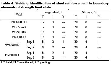
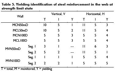
Table 4 indicates that both longitudinal and stirrup reinforcement at boundary elements of walls exhibited an elastic behavior during all testing stages, except one longitudinal bar and one stirrup at a boundary element of a wall with openings. The small magnitude of strains is consistent with the design criterion by which specimens were purposely dimensioned and detailed to attain a shear failure, as that observed in RC walls for low-rise housing.
Figures 4 to 6 show that yielding of web steel reinforcement was recorded at the strain gauges located close to the inclined cracks. For walls reinforced with welded-wire mesh, yielding of reinforcement was recorded at the strain gauges located close to the major inclined crack where all vertical and horizontal wires were fractured, and then, failure of walls was observed (Figure 4). For walls with hw/lw=1 and reinforced with deformed bars, yielding of horizontal and vertical reinforcement in the web was recorded at the strain gauges located at the central middle portion of the wall web, and in the upper middle portion of the web where damage of those models was concentrated, respectively (Figure 5).
Table 6 shows the yielding progress of web steel reinforcement until the earthquake record where strength limit state was observed. The table shows that yielding of reinforcement of all walls was initiated and focused at the horizontal web bars/wires. However, similar to the walls tested under quasistatic lateral load (Sánchez, 2010), layout of yielding of horizontal web reinforcement along the wall diagonals varied with wall height (see Figures 4 to 6). In addition, all the horizontal web reinforcement did not yield when wall peak shear strength was reached. In general, yielding of horizontal web reinforcement along the wall diagonals was concentrated at the zones where inclined cracks were observed; that is, at the central, middle region (around midheight and midlength) of the walls with hw/lw=1, and at the upper middle portion of segment 2 of walls with openings.
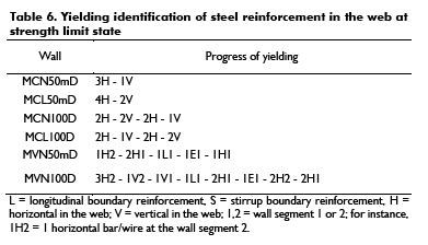
Although yielding initiated and focused at the horizontal reinforcement in the web, yielding also was recorded at some vertical bars or wires in the web (see Table 6). To analyze the effect of web reinforcement in the behavior of walls, strains measured at vertical bars or wires should be firstly modified because border conditions of walls in the prototype were slightly different to those of walls in the tests. It is considered that the two effects that modify the strains on vertical web reinforcement are the concentration of longitudinal reinforcement at boundary elements and rotation at top wall. However, measured results demonstrated that strains in the vertical web reinforcement were mainly associated with the uniform distribution of inclined cracks.
Strains in web reinforcement
Tables 7 and 8 show strains measured in wall reinforcement. Strains described in the tables are associated to wall peak shear strength. For design purposes, the ratio between mean steel strain, measured at wall peak shear strength and yield strain, measured from coupon tests (ε/εy ≤ 1.0) are included in the tables. This factor can be used as an efficiency factor to reflect the amount of wall reinforcement at yielding.
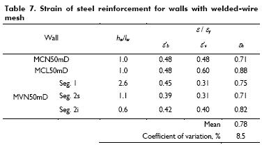
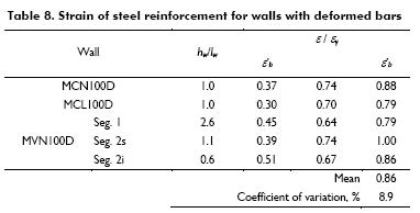
It is readily apparent from Tables 7 and 8 that web steel contribution to wall shear strength was fundamentally associated with the horizontal reinforcement. It is noted that contribution of horizontal web reinforcement to wall shear strength mainly depends on the type and amount of web reinforcement, and is independent of hw/lw. For instance, the efficiency factor of horizontal web reinforcement, measured in walls reinforced with deformed bars and the minimum codeprescribed steel ratio, was 86%. The efficiency factor measured in walls using welded-wire mesh and half of the minimum specified by ACI 318-11 was 78%. Although results of walls with four values of hw/lw are included in the estimation of contribution of horizontal web reinforcement, coefficients of variation are low; i.e., 8.5% and 8.9% for walls with welded-wire mesh and deformed bars, respectively. Regarding the mean value of the efficiency factor, it is noted that yielding of all horizontal web reinforcement was never measured; therefore, the efficiency factor was always smaller than 1.0.
Conclusions
Both longitudinal and stirrup reinforcement at boundary elements of walls exhibited a small magnitude of strains and almost elastic behavior during all testing stages. Yielding of web steel reinforcement was recorded at the strain gauges located close to the inclined cracks. For walls reinforced with welded-wire mesh, yielding of reinforcement was recorded at the strain gauges located close to the major inclined crack where all vertical and horizontal wires were fractured, followed by observation of brittle failure of walls. Although yielding of all walls focused at the horizontal web bars/wires, its yielding layout along the wall diagonals varied with wall height. Yielding also was recorded at some vertical bars or wires in the web and the related strains were mainly associated with the uniform distribution of inclined cracks. Consistent with the latter, web steel contribution to wall shear strength was fundamentally associated with horizontal reinforcement. Such a contribution mainly depends on the type and amount of web rein-forcement and is independent of hw/lw.
It is implicitly assumed by ACI 318-11 that the efficiency factor of horizontal wall reinforcement is constant and equal to 1.0 at all amounts of reinforcement and all ranges of hw/lw. In summary, it is assumed in ACI 318 that all horizontal web reinforcement will attain yielding at wall shear strength. Results of this study confirm the assumption of ACI 318-11 with regard to the lack of dependency on hw/lw. However, measured results contrast with the postulation of ACI 318-11 about the full efficiency and that the contribution is independent of the type of web reinforcement. For example, the efficiency factor of horizontal web reinforcement was always smaller than 1.0, such as 0.86 for walls reinforced with deformed bars and the minimum codeprescribed steel ratio and 0.78 in walls using welded-wire mesh and half of the minimum specified by ACI 318-11. As it is demonstrated by Carrillo et al. (2014), results of this study can be used as a tool to evaluate the contribution of reinforcement to the behavior of low-rise RC walls in terms of shear strength and displacement capacity.
Acknowledgments
The authors gratefully acknowledge the financial support from the Research Office (Vicerrectoría de Investigaciones) at Nueva Granada Military University (UMNG, Colombia), through project number IMP-ING-1574.
References
ACI Committee 318., Building code requirements for structural concrete (ACI-318) and commentary (ACI-318R)., Farmington Hills, MI, American Concrete Institute, 2011. [ Links ]
Carrillo, J., Alcocer, S., Seismic performance of concrete walls for housing subjected to shaking table excitations., Journal of Engineering Structures, Vol. 41, 2012, pp. 98-107. [ Links ]
Carrillo, J., Guzmán, A., Jerez, S., Reinforcement contribution to the behaviour of low-rise concrete walls., Latin American Journal of Solids and Structures, In Press, 2014. [ Links ]
NSR-10. Colombian code for earthquake-resistant construction., Colombia, Colombian Association of Earthquake Engineering, AIS, 2010. [ Links ]
Sánchez, A., Seismic behavior of housing with concrete walls., Technical Report, Institute of Engineering, National University of Mexico, UNAM, 2010 (in Spanish). [ Links ]
