


Services on Demand
Journal
Article
 English (pdf)
 Article in xml format
 Article references
 Send this article by e-mail
Indicators
-
 Cited by SciELO
 -
 Access statistics
Related links
-
 Cited by Google
 -
 Similars in
SciELO
Similars in
SciELO -
 Similars in Google
Share

 Permalink
Ingeniería e Investigación
Print version ISSN 0120-5609
Ing. Investig. vol.34 no.2 Bogotá May/Aug. 2014
https://doi.org/10.15446/ing.investig.v34n2.39607
http://dx.doi.org/10.15446/ing.investig.v34n2.39607
F. H. Escobar1, Y. L. Zhao2 and L. H. Zhang3
1 Freddy Humberto Escobar. Ph. D., Oklahoma University, USA. Affiliation: Professor, Universidad Surcolombiana/CENIGAA, Colombia. E-mail: fescobar@usco.edu.co
2 Yu Long Zhao. Ph. D., State Key Laboratory of Oil and Gas Reservoir Geology and Exploitation, Southwest Petroleum University, China. Affiliation: Lecturer, South-west Petroleum University, China. E-mail: 373104686@qq.com
3 Lie Hui Zhang. Ph. D., Affiliation: State Key Laboratory of Oil and Gas Reservoir Geology and Exploitation, Southwest Petroleum University, Professor, Southwest Petroleum University, China. zhangliehui@vip.163.com
How to cite: Escobar, F. H., Zhao, L. Y., & Zhang, L. H. (2014). Interpretation of Pressure Tests in Hydraulically Fractured Wells in Bi-Zonal Gas Reservoirs. Ingeniería e Investigación, 34(2), 76-84.
ABSTRACT
Due to the recent increase in the fracturing of low permeability formations, mathematical wellbore data interpretation has become important to generate mathematical models to study their pressure behavior and formulate interpretation methodologies for a more accurate characterization of tight hydrocarbon-bearing formations. This paper presents an analytical methodology of interpretation using the pseudopressure and pseudopressure derivative log-log plot for the characterization of hydraulically fractured (partially or fully penetrating) vertical wells completed in bi-zonal gas reservoirs. The methodology provided uses characteristic points and lines found on the pseudopressure and pseudopressure derivative plot so that new analytical expressions and correlations are developed to estimate half-fracture length, fracture penetration ratio, mobility and storativity ratios, radial permeability, size of the inner zone, well drainage area, vertical permeability and skin factor. The new expressions were successfully verified and tested with synthetic examples.
Keywords: Pressure derivative, fractured wells, mobility ratio, storativity ratio.
RESUMEN
Dada la creciente demanda en el fracturamiento de formación de baja permeabilidad, la interpretación matemática de datos de pozos se ha tornado importante para la generación de modelos matemáticos que estudien el comportamiento de la presión y se formulen metodologías para una caracterización más exacta de formaciones apretadas que contienen hidrocarburos. Por ende, en este artículo se presenta una metodología para interpretar pruebas de presión en yacimientos gasíferos bi-zonales drenados por un pozo vertical hidráulicamente fracturado (penetración parcial o complete) que utiliza el gráfico log-log de pseudopresión y derivada de pseudopresión. La metodología dada usa líneas y puntos característicos hallados en dicho gráfico de modo que se desarrollaron nuevas expresiones y correlaciones para longitud media de fractura, relación de penetración de la fractura, relaciones de movilidad y almacenaje, permeabilidad radial, tamaño de la zona interior, área de drenaje, permeabilidad vertical y factores de daño. Las expresiones nuevas se verificaron exitosamente mediante ejemplos sintéticos.
Palabras clave: Derivada de presión, pozos fracturados, relación de movilidad, relación de almacenaje.
Received: August 2th 2013 Accepted: February 11th 2014
Introduction
Hydraulic fracturing has been used extensively over the past 50 years to stimulate low permeability hydrocarbon wells. Currently, fracturing is very active for horizontal wells in gas shale formations. The study of the pressure behavior of fractured wells is of great importance to the petroleum industry.
Transient tests in wells in low-permeability gas formations were conducted by Lee and Holditch (1981) using both conventional analysis and type-curve matching. They also presented several field examples. The importance of fracturing low permeability gas reservoirs on the recovery factor of gas systems was addressed by Lemon, Patel and Dempsey (1974).
Raghavan, Uraiet and Thomas (1976) presented an analytical solution to study the pressure behavior of vertical fractured wells inside of an infinite-size reservoir when the well does not penetrate the entire pay zone. They provided type curves for the interpretation of pressure tests in such systems for cases on uniform-flux and infinite-conductivity fractures. Holditch, Lee and Gist (1983) used a conventional analysis for estimating reservoir and fracture parameters from pressure buildup tests using conventional techniques by introducing an iterative technique. Rodriguez, Horne, and Cinco-Ley (1984) introduced a semi-analytical solution to study the transient flow behavior of a partially penetrating finite-conductivity vertical fracture. For such systems during the early-time period, the flow behavior is equivalent to a fully penetrating fracture. In this period, either bilinear or linear flow periods are observed, depending upon fracture conductivity.
Tiab (1994) and Tiab et al. (1999) presented interpretation techniques for infinite- and finite-conductivity fractures in oil wells based on the pressure and pressure derivative plot without using type-curve matching. An extension of the former work to gas wells was performed by Nunez-Garcia, Tiab and Escobar (2003).
For fractured wells in a composite reservoir, Chu and Shank (1993) presented a mathematical model for both finite-conductivity or uniform-flux vertically fractured wells within a composite reservoir. Chen and Raghavan (1995) developed a model for a fractured well producing in a composite reservoir. They also addressed some computational issues during the computation of the products In(x)?Kn(x). Feng et al (2009) proposed a seepage flow model for a fractured heterogeneous composite reservoir using the equivalent flowing resistance method. However, few of these authors considered the effect of wellbore storage and skin factors in their models. They also excluded the partial penetration effect of the hydraulic fracture.
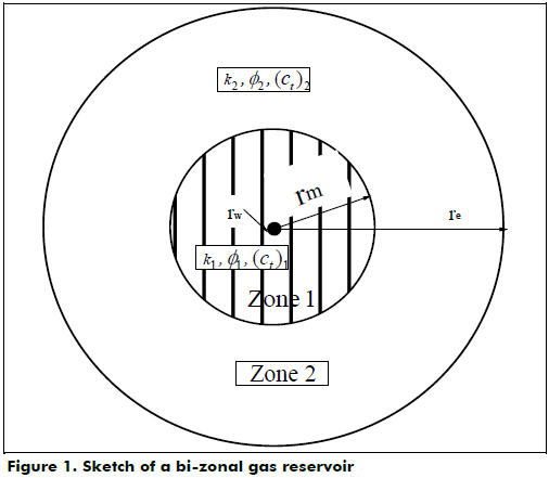
Zhao et al. (2013) presented novel analytical solutions for both partially or fully penetrating vertical fractured wells in a composite (bi-zonal) gas reservoir, as depicted in Figure 1. Their formulation used the continuous point source functions in an anisotropic reservoir on the basis of source function theory along with the Laplace transformation method and the Duhamel's principle. The analytical solutions were obtained using the constructing function and the continuous point source functions for wells in bi-zonal gas reservoirs with upper and lower boundaries closed.
The present work uses the solutions presented by Zhao et al. (2013) to understand pseudopressure and pseudopressure derivative behaviors so several unique features on this plot are used to generate several expressions for characterizing the reservoir. The expressions that we developed were tested successfully with synthetic examples.
Mathematical model
Zhao et al. (2013) presented an analytical solution for the pressure response of a fully penetrating hydraulically fractured gas well in a bi-zonal reservoir,
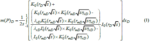
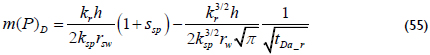
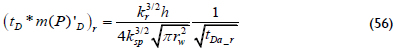
For the case of a partially penetrating fracture well, Zhao et al. (2013) also presented the following solution:
Pseudopressure and Pseudopressure Derivative behaviors
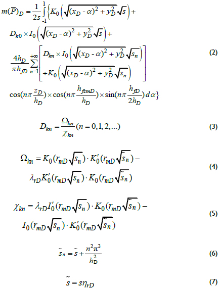
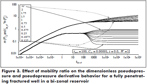
Although Zhao et al. (2013) explain the pressure behavior of the systems under consideration, it is important to establish the main flow regimes that can be presented in fractured wells within bi-zonal reservoirs. The dimensionless pseudopressure and pseudopressure derivative plot is shown in Figure 2. The dashed lines correspond to a fracture that penetrates half of the reservoir thickness, while the solid line is for a fully penetrating fracture. These curves allow the clear observation of wellbore storage effects at a very early time. Then, the formation linear flow regime to the hydraulic fracture is observed, characterized by a slope of one-half on the pseudopressure derivative curve. The bi-radial flow regime may also be presented in fractured wells having infinite conductivity, as shown in Figure 2, observed once linear flow vanishes. For the plot provided, bi-radial flow occurs during a dimensionless pseudotime between 0.01 and 1 and is recognized by a slope of 0.36 on the derivative curve. For the case of a fully penetrating fracture, radial flow follows once the fracture effects are no longer felt in the test. However, as observed in the dashed curves of Figure 2 corresponding to a partially penetrating fracture, spherical flow takes place. The spherical flow possesses a negative one-half slope on the derivative curve. In both cases, radial flow in zone 1 develops at a dimensionless pseudotime of approximately 10, followed by a horizontal pattern of the derivative known as a radial flow regime in zone 1 (see Figure 3). At the end of the test (tDa_xf > ~20000), a second plateau is observed corresponding to the radial flow regime in zone 2. As Figure 3 shows, depending on the value of M, the second plateau will be above or below the level of the radial flow regime during zone 1. For values of M > 1, the second plateau is higher than the first plateau and vice versa.
Another remarkable feature is provided in Figure 4. If the storativity ratio is smaller than unity, the derivative displays a minimum, then continues to the second plateau. For storativity ratios greater than one, the derivative displays a maximum point before forming the second plateau. As the values are farther than one, both the maximum and minimum values are more pronounced.
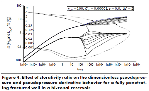
Notice that the differences of the dimensionless wellbore storage coefficient values and dimensionless radii in Figures 2 to 4 do not represent any effect on the governing equations for the generation of the TDS Technique.
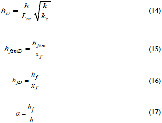
Dimensionless Parameters
The dimensionless quantities are defined as:
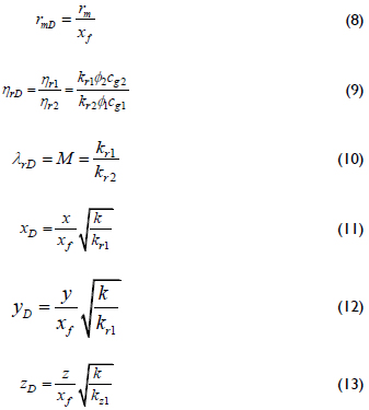
with k as the effective permeability of the bi-zonal reservoir,
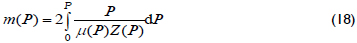
For compressible fluids, the pseudopressure, m(P), introduced by Agarwal (1949) is given by:
Agarwal (1949) also introduced the pseudotime function to account for the time dependence of gas viscosity and total system compressibility:
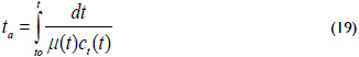
Pseudotime is better defined as a function of pressure as a new function given in hr psi/cp:
Pseudotime instead of rigorous/normal time is used in this work because Escobar et al. (2012) demonstrated that the hydraulic fracture parameters are better estimated using pseudotime than rigorous time.
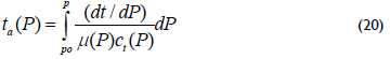
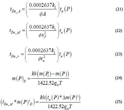
The system under consideration is assumed to possess a partially penetrating hydraulic fracture in a vertical well that has a half-length, xf, width, wf, and permeability, kf. The dimensionless pseudotime, pseudopressure and pseudopressure derivative are defined as:
Infinite-conductivity fractures - Linear flow regime
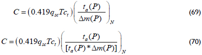
The interpretation methodology follows the philosophy of the Tiab's Direct Synthesis technique introduced by Tiab (1993). Rodriguez et al. (1984) presented an analytical solution for the well pressure behavior of a partially penetrating fracture that is adapted here as:

And the pseudopressure derivative is

After replacing the dimensionless quantities given by Equations 23 to 25 into Equations 26 and 27, the results shown below are obtained.
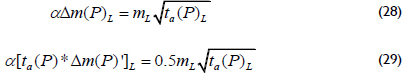
where
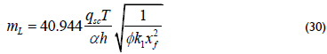
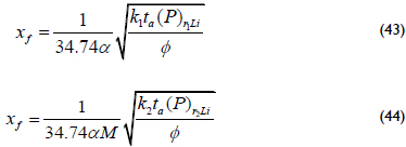
Solving for xf from Equations 28 and 29 yields;
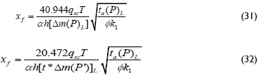
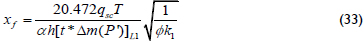
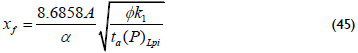
Equations 31 and 32 allow the estimation of the half-fracture length using either the value of differential pseudopressure or pseudopressure derivative read at any arbitrary pseudotime point during the linear flow regime. Extrapolation of the pseudopressure derivative at the pseudotime value of 1 hr psi/cp is recommended. Read the pseudopressure derivative at a pseudotime value of 1 hr psi/cp. Under these conditions, Equation 31 becomes:
It is preferred to leave the term a in Equations 31 to 32 so that it takes the value of one for fully penetrating hydraulic fractures.
The solution of the diffusivity equation during the radial flow regime of the internal zone, zone 1, is:

From such an equation, Escobar, Lopez and Cantillo (2007) developed the equations for permeability and skin factor, including pseudotime:
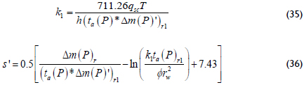
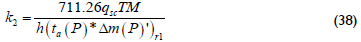
Figure 3 shows that the solution of the diffusivity equation during the radial flow regime of zone 2 related to the radial flow regime of zone 1 is:

From which the permeability of zone 2 is found as:
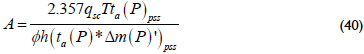
Although the pseudosteady state regime is not shown in the plots given, the governing equation during the late pseudosteady-state regime as used by Escobar et al. (2007) is given by:

An expression from Equation 39 obtains the reservoir drainage area from an arbitrary pressure derivative point during the pseudosteady state:
Again, it is better to extrapolate the pseudopressure derivative at a pseudotime of 1 hr psi/cp.
The reservoir drainage area can also be determined from the intercept of Equation 39 with Equations 34 and 37:
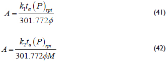
The half-fracture length can also be verified or re-estimated from the intercept point between the linear and the two radial lines, v.g. Equations 29, 34 and 37:
It is necessary to change k2 by k1 when M<1. Additionally, the verification of the half-fracture length from the intercept point between the linear and pseudosteady-state lines, v.g. Equations 29 and 39:
Infinite-conductivity fractures - Bi-radial flow regime
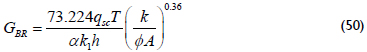
The governing dimensionless pressure and pressure derivative equations presented by Tiab (1994) during bi-radial flow applied to gas systems were rearranged by Escobar et al. (2012) for gas flow:
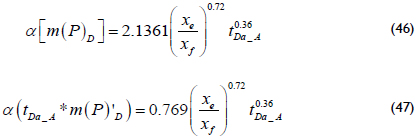
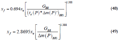
Once the dimensionless quantities given by Equations 21, 24 and 25 are replaced into Equations 46 and 47 and then solved for the half-fracture length, the following equations are obtained:
Being:
Equation 47 is set equal to 0.5 and 0.5 M during the radial flow regimes of zones 1 and 2, respectively, corresponding to the intersection point of the radials and bi-radial lines. Then, the following equations are derived:
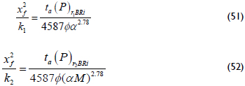
The intersection point of the bi-radial and late pseudosteady-state lines, Equations 47 and 39, leads to another expression to find the reservoir permeability:
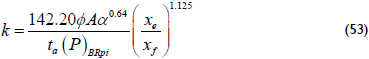
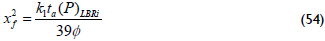
It is also necessary to change k2 by k1 when M<1. The intersection between the linear and bi-radial lines, Equations 27 and 47, produces the following expression:
Spherical flow regime
The analytical solution presented by Joseph (1984) and extended to gas flow with the pseudotime function condition is given below:
Which pseudopressure derivative is:
Moncada et al. (2004), using the solution presented by Joseph (1984), provided an interpretation technique using the pressure derivative curve for spherical and hemispherical flow of oil and gas reservoirs. Their solution for gas using rigorous time is extended here for pseudotime, so the spherical permeability and the skin factor caused by spherical flow can be estimated using any arbitrary pseudotime point during spherical flow on which values of pseudopressure and pseudopressure derivative curves are read to be used in the following expressions:
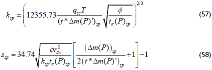
In wich;
The intersection of the radial flows and the spherical flow lines, i.e., Equations 34, 37 and 56, obtain:
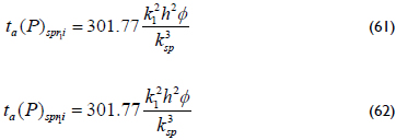
It is also found in this work that the intersection point formed by the linear and the spherical flow lines, Equations 27 and 56, provide a new expression to estimate the half-fracture length:
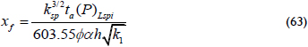
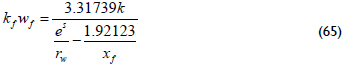
The point of interception between Equations 47 and 56, bi-radial and spherical flow lines, allows obtaining another expression for the estimation of the half-fracture length:
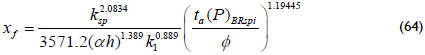
Tiab (2003) developed the following equation to relate the half-fracture length, formation permeability, fracture conductivity and post-fracture skin factor:
The determination of the skin facture requires running two flow tests at different gas flow rates. A single test provides the pseudoskin factor as given by Equation 36.
Wellbore Storage Effects
If wellbore storage effects are presented, the solution of the early-time diffusivity equation (Tiab (1993)) reduces to:

For which the dimensionless wellbore storage is given by:
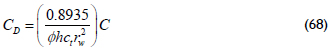
Expressions to estimate the wellbore storage coefficient are found by replacing the respective dimensionless quantities into the above equations so that:
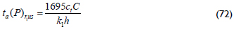
The intersection of the early unit-slope line, Equation 68, with the radial horizontal straight line, Equation 34, gives:
From this expression, an equation to estimate either permeability or wellbore storage is obtained once the dimensionless parameters are replaced:
Furthermore, another expression is obtained from the intersection point of the unit-slope line, Equation 68, with the radial flow of zone 2, Equation 37, to give:
Mobility ratio, Inner radius and Storativity
Figure 3 shows that there exists a relationship between the mobility ratio and the pressure derivative in the second plateau. This empirical relationship with a correlation coefficient (R2) of 1 is given by:
Forming the radial flow of zone 2 requires almost two log cycles that involve many testing times. There may be cases in which the second plateau formed by the radial flow in zone 2 may not be observed or is too noisy. In such cases, it is useful to use the inflection point formed between the two radial flow lines. This inflection point is normally difficult to see. A better option is to take the second derivative and relate this second derivative to the value of the pressure derivative of the radial flow in zone 1. This value will be used in a correlation with a correlation coefficient (R2) of 0.9982 to determine the value of M so

Another correlation with a correlation coefficient (R2) of 0.9998 is found below.

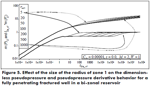
Figure 5 allows the observation of the duration of the radial flow of zone 1 as a function of the radius of zone 1. The radius can be estimated with the following correlation that possesses a correlation coefficient (R2) of 0.99943 and uses the ending time of the radial flow regime in zone 1.
Finally, with observations from Figure 4, it is possible to establish a relationship (using more curves than the curves given in the plot) between either the maximum or minimum, the mobility ratio, M, and the storativity ratio, as follows.
Where constants a and b are expressed as:
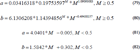
An average correlation coefficient of 0.9989 is found for the set of empirical Equations 78 through 82.
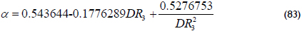
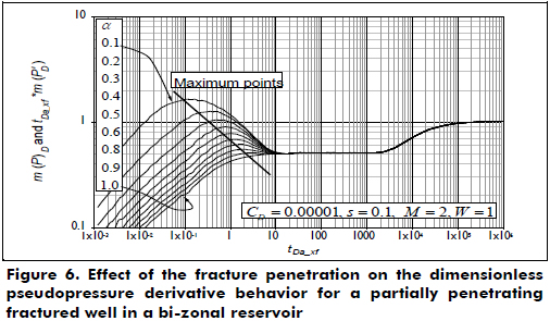
Figure 6 allows the observation of another important feature. As the penetration ratio, hf/h, referred to here as a, reduces its value, the derivative displays a "hunch" before the radial flow regime starts. The maximum value of the pseudopressure derivative was correlated against a, giving the expression below that possesses a correlation coefficient (R2) of 0.9998:
Synthetic Examples
Example 1
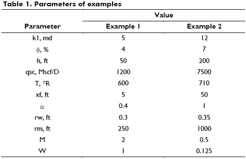
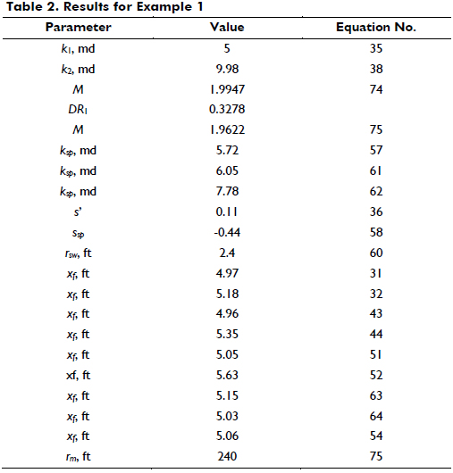
The data provided in the second column of Table 1 were used to simulate a pressure test where pseudopressure, pseudopressure derivative and second pseudopressure derivative against pseudotime are given in Figure 7.
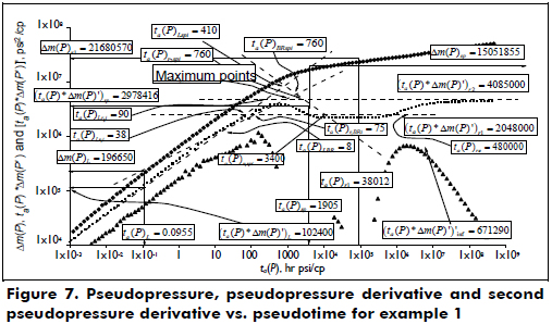
Determine the reservoir permeability, mobility ratio, pseudoskin factors, fracture length and the radius of zone 1.
Solution. Several flow regimes are observed in this test. In chronological order, these flow regimes are linear, bi-radial, a maximum caused by the partial penetration effect of the fracture, radial flow in zone 1, a transition period and a final radial flow regime in zone 2. The following information was read from Figure 7, and units are not reported for space-saving purposes:
ta(P)r1= 38012 hr*psi/cp
Δm(P) r1 = 21680570 psi2 /cp
ta(P)*Δm(P)'
ta(P)*Δm(P)'r2 = 4085000 psi2/cp
[ta(P)*Δm(P)']'inf= 671290 psi2/cp
ta(P)*Δm(P)'max = 3592000 psi2/cp
ta(P)L= 0.0955 hr*psi/cp
Δm(P)L= 196650 psi2/cp
ta(P)*Δm(P)'L = 102400 psi2/cp
ta(P)r1Li = 38 hr*psi/cp
ta(P)r2Li = 90 hr*psi/cp
ta(P)spr1Li = 3400 hr*psi/cp
ta(P)spr2Li = 1600 hr*psi/cp
ta(P)sp = 1905.2 hr*psi/cp
Δm(P)sp= 196650 psi2/cp
ta(P)*Δm(P)'sp = 102400 psi2/cp
ta(P)spLi = 410 hr*psi/cp
ta(P)spBRi = 410 hr*psi/cp
ta(P)re = 48000 hr*psi/cp
ta(P)r1BRi = 75 hr*psi/cp
ta(P)r2BRi = 320 hr*psi/cp
Using the pseudopressure derivative value during radial flow of zone 1 in Equations 35 and 38, values of k1 = 5 and k2 = 9.98 md were found. Then, the maximum point found after the bi-radial flow regime divided by the pseudopressure derivative value read during the radial flow regime of zone 1 allows for the estimation of a pseudopressure derivative ratio, DR3, of 1.7539. This ratio leads to a calculation of a value of 0.4036 by means of Equation 77. The ratio between the two values of the radial flow regimes provides a value of M of 1.9947 with Equation 74. The arbitrary values of pseudotime, pseudopressure and pseudopressure derivative during the linear flow regime are used to calculate a half-fracture length, xf, of 4.97 and 5.18 ft using Equations 31 and 32. The estimation of other parameters along with the equations used is given in Table 2.
Example 2
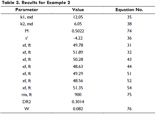
Figure 8 presents pseudopressure and pseudopressure derivative versus pseudotime simulated with the data provided in the third column of Table 1. The estimation of reservoir permeability, pseudoskin factor, half-fracture length, storativity and the radius of zone 1 is required.
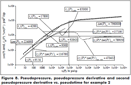
Solution. Figure 8 shows that the following flow regimes take place: linear, radial, radial flow in zone 1, then a minimum flow caused by the storativity ratio followed by the radial flow in the second zone. The following parameters, which are useful for the calculations, are obtained from Figure 8.
ta(P)r1= 928420 hr*psi/cp
Δm(P)r1 = 7960000 psi2/cp
ta(P)*Δm(P)'r1 = 1571000 psi2/cp
ta(P)*Δm(P)'r2 = 789050 psi2/cp
ta(P)*Δm(P)'max_min = 473432 psi2/cp
ta(P)L= 95.56 hr*psi/cp
Δm(P)L= 224051 psi2/cp
ta(P)*Δm(P)'L = 116780 psi2/cp
ta(P)r1Li = 17800 hr*psi/cp
ta(P)r2Li = 4200 hr*psi/cp
ta(P)re = 500000 hr*psi/cp
ta(P)r1BRi = 65000 hr*psi/cp
ta(P)r2BRi = 9300 hr*psi/cp
As shown in example 1, the first parameters to be calculated are the permeabilities in both zones by using Equations 35 and 37. Then, an estimation of the mobility ratio with Equation 74 is required. The results of these calculations are reported in Table 3 along with some other values.
Analysis of Results
Very close agreement was found in the estimation of the half-fracture length, permeability, and mobility ratio of the given examples if compared with the actual values. By simple inspection, small differences are obtained. Although the estimation of the storativity ratio is not exact because of its sensitivity, the authors agree that the values provided by the empirical expressions are acceptable.
Conclusion
Several new expressions were obtained for characterizing pressure tests run in a bi-zonal gas reservoir drained by a hydraulically fractured well considering either full or partial penetration. The estimated parameters were satisfactory compared to actual values determined by working synthetic pressure tests. The interpretation technique provided allows for the the verification of some parameters. At minimum, ten different expressions for estimating half-fractured length were provided. Permeability and mobility can also be verified.
Acknowledgments
The authors thank the sponsorship of The National Science Fund for Distinguished Young Scholars of China (Grant No. 51125019), the Center for Research in Sciences and Geo-Agro-Environmental Resources (Centro de Investigación en Ciencias y Recursos Geoagroambientales), CENIGAA, and Universidad Surcolombiana.
Nomenclature
A Reservoir drainage area, ft2
C Wellbore storage coefficient, Mscf/psi
DR1 [ta(P)*Δm(P)']'inf/[ ta(P)*Δm(P)']r1
DR2 [ta(P)*Δm(P)']max_min/[ ta(P)*Δm(P)']r1
DR3 [ta(P)*Δm(P)']max/[ ta(P)*Δm(P)']r1
c Compressibility, 1/psi
h Formation thickness, ft
hf Fracture height, ft
hfzm Distance from the fracture middle point to the reservoir's bottom boundary, ft
k1, kr1 Radial/horizontal permeability of zone 1, md
k2, kr2 Radial/horizontal permeability of zone 2, md
kfwf Fracture conductivity, md-ft
kh Horizontal permeability of zone 1, (kxky)0.5 md
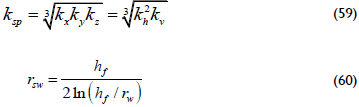
ksp Spherical permeability of zone 1, md
kx x-direction permeability, md
ky y-direction permeability, md
kv, kz Vertical permeability of zone 1, md
Lre Reservoir length, ft
M Mobility ratio, kr1/kr2
m(P) Pseudopressure function, psi2/cp
m( ) Pseudopressure in Laplace domain
P Pressure, psi
qsc Gas flow rate, Mscf/D
rm Distance from well to the end of zone 1, ft
rw Well radius, ft
rsw Spherical flow radius, ft
s Skin factor
ssp Peudoskin factor in the spherical flow
s' Pseudoskin factor
T Temperature, oR
t Time, hr
ta(P) Pseudotime function, psi hr/cp
[ta(P)*Δm(P)'] Pseudopressure derivative function, psi2/cp
[ta(P)*Δm(P)']' Second pseudopressure derivative function, ppsi2/cp
[ta(P)*Δm(P)']max_min Maximum or minimum pseudopressure
w derivative function after radial flow of zone 1, psi2/cp
[ta(P)*Δm(P)']max Maximum pseudopressure derivative function before radial flow of zone 1, psi2/cp
tDa_r Dimensionless pseudotime with respect to rw
tDa_A Dimensionless pseudotime with respect to A
tDa_xf Dimensionless pseudotime with respect to xf
xe Reservoir half length, ft
xf Half-fracture length, ft
DR1 [ta(P)*Δm(P)']'inf/[ta(P)*Δm(P)']r1
DR2 [ta(P)*Δm(P)']max_min[ta(P)*Δm(P)']r1
DR3 [ta(P)*Δm(P)']max/[ta(P)*Δm(P)']r1
x Reservoir length in x-direction
xe Half-reservoir length
y Reservoir length in y-direction
z Reservoir length in z-direction
Z Gas deviation factor
Greek
αFracture penetration ratio, hf/h
ΔChange, drop
φPorosity, fraction
μViscosity, cp
ηr1 Diffusivity constant of zone 1
Suffixes
1 Zone 1
2 Zone 2
BR Bi-radial
BR1 Bi-radial at pseudotime of 1 psi*hr/cp
BRpi Intersect of bi-radial and pseudosteady-state lines
BRLi Intersect of bi-radial and linear lines
BRspi Intersect of bi-radial and spherical lines
D Dimensionless
e External
g Gas
i Intersection or initial conditions
inf Inflection point
L Linear
L1 Linear flow at pseudotime of 1 psi*hr/cp
Lpi Intersect of linear and pseudosteady-state lines
min Minimum
N A point on the early unit-slope line
o Reference value
p, pss Pseudosteady state
r radial flow
r1 Radial flow in zone 1
r2 Radial flow in zone 2
r1us Intersection of radial flow in zone 1 with early unit-slope line
r2us Intersection of radial flow in zone 2 with early unit-slope line
rBRi Intersection of radial and bi-radial flow regimes
re End of radial flow regime in zone 1
rLi Intersection of radial and linear flow regimes
rpi Intersection of radial and pseudosteady-state lines
sc Standard conditions
sp Spherical flow
spr1i Intersection of spherical and radial in zone 1 lines
spr2i Intersection of spherical and radial in zone 2 lines
t Total
us Early unit-slope during wellbore storage effects
w Well
References
Agarwal, G. (1979, Sep.). Real Gas Pseudo-time a New Function for Pressure Buildup Analysis of MHF Gas Wells (SPE 8279). Paper presented at the 54th technical conference and exhibition of the Society of Petroleum Engineers of AIME held. Las Vegas, NV. [ Links ]
Chen, C. C., & Raghavan, R. (1995). Modeling a fractured well in a composite reservoir. SPE Formation Evaluation,(10), 241-246. [ Links ]
Chu, W. C., & Shank, G. D. (1993).A new model for a fractured well in a radial, composite reservoir (includes associated papers 27919, 28665 and 29212). SPE Formation Evaluation, (8), 225-232. [ Links ]
Escobar, F. H., López, A. M., & Cantillo, J. H. (2007). Effect of the Pseudotime Function on Gas Reservoir Drainage Area Determination., CT & F - Ciencia, Tecnología y Futuro, 3(3), 113-124. [ Links ]
Escobar, F. H., Martinez, L. Y., Méndez, L. J., & Bonilla, L. F. (2012). Pseudotime Application to Hydraulically Fractured Vertical Gas Wells and Heterogeneous Gas Reservoirs Using the TDS Technique. Journal of Engineering and Applied Sciences, 7(3), 260-271. [ Links ]
Feng, J. D., Luo, R. L., Chen, L. S., Chang, Y. W., & Yu, L. J. (2009, March). A composite seepage model for fractured reservoir (SPE 119255). Paper presented at SPE Annual Technical Conference and Exhibition. Bahrain. [ Links ]
Holditch, S.A., Lee, J., & Gist, S. R. (1983, May). An Improved technique for Estimating Permeability, Fracture Length, and Fracture Conductivity from Pressure-Build Tests in Low-Permeability Gas Wells (pp. 981-990). Society of Petroleum Engineers of AIME. [ Links ]
Joseph, J. A. (1984). Unsteady-State Cylindrical, Spherical and Linear flow in Porous Media. Ph.D. dissertation, U. of Missouri-Rolla. [ Links ]
Lee, J., & Holditch, S. A. (1981). Fracture Evaluation with Pressure Transient Testing in Low Permeability Gas reservoirs. Journal of Petroleum Technology, 1776-1792. [ Links ]
Lemon, R. F., Patel, H. J., & Dempsey, J. R. (1974). Effects of Fracture and Reservoir Parameters on recovery from Low Permeability Gas Reservoirs (SPE 5111). [ Links ]
Moncada, K., Tiab, D., Escobar, F. H., Montealegre-M, M., Chacon, A., Zamora, R. A., & Nese, S. L. (2005). Determination of Vertical and Horizontal Permeabilities for Vertical Oil and Gas Wells with Partial Completion and Partial Penetration using Pressure and Pressure Derivative Plots without Type-Curve Matching. CT & F - Ciencia, Tecnología y Futuro, 2(6), 77-95. [ Links ]
Nunez-García, W., Tiab, D., & Escobar, F. H. (2003, March). Transient Pressure Analysis for a Vertical Gas Well Intersected by a Finite-Conductivity Fracture (SPE 80915). Paper presented at SPE Production and Operations Symposium. Oklahoma City, Oklahoma, USA. [ Links ]
Raghavan, R., Uraiet, A., & Thomas, G. W. (1976, Oct.). Vertical Fracture Height: Effect on Transient Flow Behavior (SPE 6016). Paper first presented at the SPE-AIME Annual Fall Technical Conference. [ Links ]
Rodriguez, F., Horne, R. N. & Cinco-Ley, H. (1984, April). Partially Penetrating Fractures: Pressure Transient Analysis of an Infinite Conductivity Fracture (SPE 12743). Paper presented at the 1984 California Regional Meeting. Longbeach, CA. [ Links ]
Tiab, D. (1994). Analysis of Pressure Derivative without Type-Curve Matching: Vertically Fractured Wells in Closed Systems. Journal of Petroleum Science and Engineering, 11, 323-333. [ Links ]
Tiab, D. (1993). Analysis of Pressure and Pressure Derivative without Type-Curve Matching: 1- Skin and Wellbore Storage. Journal of Petroleum Science and Engineering, 12, 171-181. [ Links ]
Tiab, D. (2003). Advances in pressure transient analysis - TDS Technique. Lecture Notes Manual. Norman, Oklahoma, USA: The University of Oklahoma. [ Links ]
Tiab, D., Azzougen, A., Escobar, F. H., & Berumen, S. (1999, March). Analysis of Pressure Derivative Data of a Finite-Conductivity Fractures by the 'Direct Synthesis Technique' (SPE 52201). Paper presented at the 1999 SPE Mid-Continent Operations Symposium. Oklahoma City, OK. [ Links ]
Zhao, Y. L., Zhang, L. H., Hu, S. Y., Zhao, J. Z., & Zhang, B. N. (2014). Transient pressure analysis of fractured well in bi-zonal gas reservoirs. Paper sent to CT & F to request publication. [ Links ]
