


Services on Demand
Journal
Article
 English (pdf)
 Article in xml format
 Article references
 Send this article by e-mail
Indicators
-
 Cited by SciELO
 -
 Access statistics
Related links
-
 Cited by Google
 -
 Similars in
SciELO
Similars in
SciELO -
 Similars in Google
Share

 Permalink
Ingeniería e Investigación
Print version ISSN 0120-5609
Ing. Investig. vol.34 no.3 Bogotá Set./Dec. 2014
https://doi.org/10.15446/ing.investig.v34n3.40835
DOI: http://dx.doi.org/10.15446/ing.investig.v34n3.40835
O. J. Romero1 and P. Almeida2
1 Oldrich Joel Romero. Mechanical Engineer, UNI, Lima, Peru. MSc, PUC-Rio, Rio de Janeiro, Brazil. DSc, PUC-Rio, Rio de Janeiro, Brazil. Affiliation: Professor, Federal University of Espirito Santo (UFES), Espirito Santo, Brazil. E-mail: oldrichjoel@gmail.com
2 Paula Almeida. BSc, Federal University of Espirito Santo (UFES). Affiliation: MSc student, Universidade Estadual do Norte Fluminense (UENF), Rio de Janeiro, Brazil. E-mail: paula-almeida@hotmail.com.br
How to cite: Romero, O. J., & Almeida, P. (2014). Microstructure, morphology, adhesion and tribological behavior of sputtered niobium carbide and bismuth films on tool steel. Ingeniería e Investigación, 34(3), 4-11.
ABSTRACT
The sucker rod pump is an artificial lift method frequently applied in onshore petroleum wells. This system can be described using a numerical simulation based on the behavior of a rod string. In the past, the elastic behavior of the rod string made it difficult to model the system. However, since the 1960s and with the advent of digital computers, it has been modeled numerically. The rod string behaves like a slender bar, and thus, the propagation of elastic waves along the bar can be represented by a one-dimensional equation. Gibbs (1963) presented a mathematical model based on the wave equation, which is described on the basis of the analysis of forces on the rod string and is incorporated into a boundary value problem involving partial differential equations. The use of the finite difference method allows for a numerical solution by the discretization of the wave equation developed in the mathematical formulation with appropriate boundary and initial conditions. This work presents a methodology for implementing an academic computer code that allows simulation of the upstroke and downstroke motion of the rod string described by the wave equation under ideal operating conditions, assuming a harmonic motion of the rod at one end and downhole pump at the other end. The goal of this study is to generate the downhole dynamometer card, an important and consolidated tool that controls the pump system by diagnosing operational conditions of the downhole pump.
Keywords: Rod string, sucker rod pump, dynamometer cards, petroleum artificial lift, finite difference method.
RESUMEN
El bombeo mecánico es un método de elevación artificial, utilizado principalmente en campos terrestres. Este sistema, puede ser entendido mediante la simulación numérica del comportamiento de la sarta de varillas, que conecta la superficie con la bomba en el subsuelo. En el pasado, el comportamiento elástico de la sarta de varillas era difícil de modelar, sin embargo, desde 1960 con el surgimiento de los computadores digitales este proceso fue facilitado.
La sarta de varillas se comporta como una barra esbelta, donde la propagación de las ondas elásticas es representada por una ecuación unidimensional y trascendente, la cual fue propuesta por Gibbs (1963), así mismo, el método de diferencias finitas permite obtener la solución numérica de dicha ecuación. En este trabajo, se explica la metodología para la implementación de un código computacional académico, que permite simular el movimiento alternativo de la sarta de varillas descrita matemáticamente por la ecuación de las ondas de Gibbs. De esta manera, se consideran como condiciones de entorno: el movimiento armónico en la superficie y la presencia de la bomba de fondo en el subsuelo, en condiciones ideales de operación.
Finalmente, el objetivo es obtener la carta dinamométrica de fondo, que es una importante y consolidada herramienta de control y diagnóstico para las condiciones operacionales de la bomba de fondo.
Palabras clave: sarta de varillas, bombeo mecánico, carta dinamométrica, elevación artificial de petróleo y diferencias finitas.
Received: November 13th 2013 Accepted: July 7th 2014
Introduction
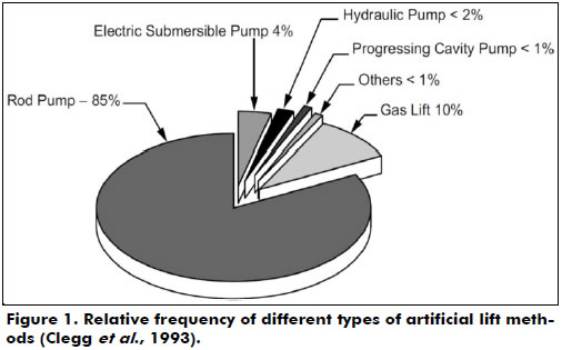
In the beginning of a petroleum reservoir's productive life, fluid lift occurs naturally because there is enough energy to raise fluids to the surface by natural lift. With the raise, this energy is gradually lost due to the decay of the reservoir's pressure. As a consequence, it is necessary to implement an artificial lift completion technique to transfer the fluid from the formation to the surface. The most common types of artificial lift are the sucker rod pump, centrifugal pump, progressive cavity pump, and gas lift. These techniques utilize specific tools to reduce the flow pressure at the bottom of the well, therefore raising the pressure differential over the reservoir (Thomas, 2004). The choice of the most appropriate lift method for each well depends on several factors, including economy, environment, security, properties of the fluids to be produced, depth of the reservoir and available equipment (Gomes, 2009). According to Takács (2002) and Clegg et al. (1993), over 85% of all petroleum wells equipped with an artificial lift use a sucker rod pump method. This high percentage can be attributed to the low cost of production throughout the productive life of a well. There are also other advantages of using this method, such as flow flexibility, energy efficiency, operation simplicity, maintenance of new facilities and availability of pumping capacity according to well conditions (Thomas, 2004).
Figure 1 shows the relative frequency of the different types of artificial lifts installed in the USA in 1992. The predominance of rod pumps (85%) indicates that the vast majority of wells are on land locations in mature fields with low well production.
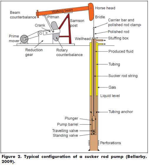
The components of a sucker rod pump system can be sorted into surface and sub-surface categories. Surface components include the motor, gearbox, pumping unit, polished rod and well head. Subsurface equipment consists of a rod string, tubing and a downhole pump (or plunger pump) submerged in the production liquid of the well. Figure 2 shows a typical installation of a sucker rod pump system. The pumping unit transforms the rotating motion given by the motor into an alternative motion to turn on the rod string. The polished rod and the stuffing box combine to make a high efficiency seal at the surface. The string moves the plunger in the lower end at the well's bottom, which transmits energy to the fluid in order to be driven to the surface.
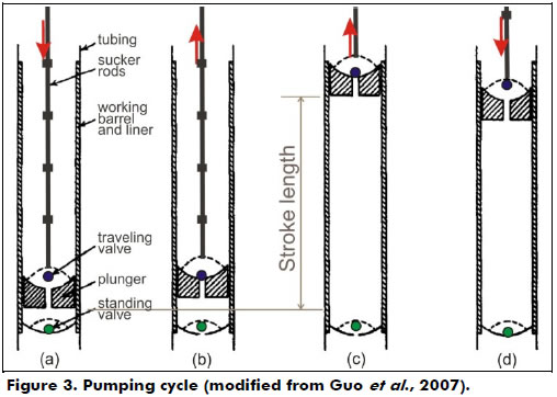
The downhole pump is installed below the dynamic liquid level. It consists of a working barrel, a plunger that is connected to sucker rods, a standing valve and a traveling valve (Figure 3). As the plunger is moved downward by the sucker rod string, the traveling valve is opened, allowing the fluid to pass through the valve; this lets the plunger move to a position just above the standing valve. During this downward motion of the plunger, the standing valve is closed, and thus, the fluid is forced to pass through the traveling valve. When the plunger is at the bottom of the stroke and begins an upward stroke, the traveling valve closes, and the standing valve opens. As the upward motion continues, the fluid in the well below the standing valve is drawn into the volume above the standing valve (fluid passing through the open standing valve). The fluid continues to fill the volume above the standing valve until the plunger reaches the top of its stroke (Guo et al., 2007).
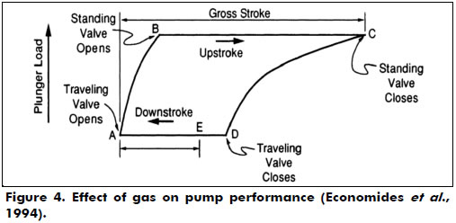
The performance characteristics of sucker rod pumps are monitored by measuring the load on the polished rod with a dynamometer. A recording of the polished rod load over one complete cycle is called the dynamometer card, which plots the polished rod load as a function of rod position. An example is presented in Figure 4 (Economides et al., 1994).
As noted by Takács (2002), "The rod string is composed of individual sucker rods that are connected to each other until the required pumping depth is reached. The sucker-rod string is the most vital part of the pumping system, since it provides the link between the surface pumping unit and the subsurface pump. It is a peculiar piece of mechanical equipment and has almost no analogies in man-made structures, being several thousand feet long and having a maximum diameter of slightly more than one inch. The behavior of this perfect 'slender bar' can have a fundamental impact on the efficiency of fluid lifting and its eventual failure leads to a total loss of production. Therefore, a properly designed rod string not only assures good operating conditions but can considerably reduce total production costs as well".
The sucker rod pump was the first method of artificial lift created in the petroleum industry, and in view of its wide usage in onshore wells, the need for studies about its behavior has risen. The application of the sucker rod pump and behavior of the rod and consequently the downhole pump can directly influence the efficiency of the lift method. For this reason, it is necessary to verify if the system is operating close to its maximum lift efficiency to avoid system stops.
Takács (2002) notes that the disadvantages of using a sucker rod pump are limited depth of pumping, limited mechanical resistance of material of rods and free gas presence in the pump's admission, which is related to a gas locking problem. Additionally, application in deactivated wells causes friction in metallic parts and can provoke mechanical failures. A heavy pump unit that occupies a large space on a surface drastically reduces the pumping efficiency. In the case of mature oil fields, the wellbore fluid behavior becomes complex, and the production and pumping efficiency gradually decline (Suling et al., 2013).
Gas locking has been a problem accompanying the ball and seat sucker rod pump ever since the inception of this pump into the oil industry. A gas lock occurs when a gas influx from the standing valve causes the pressure exerted by the fluid below the traveling valve in the closed chamber to not be able to overcome the weight of the liquid column lying above the traveling valve in the pump barrel. Figure 4 illustrates this effect on the dynamometric card. This fails to lift the ball off of the seat. Gala (2013) addressed this problem by proposing the design of a sucker rod pump consisting of a solenoid actuated hydraulic valve in the traveling plunger seat.
Gareeb and Beck (2013) discussed the main concepts in sand handling by highlighting some exclusion devices, which provided the most practical solution for best sand handling pump and completion design as a function of conditions. Jiménez et al. (2013) presented an application in heavy and extra heavy oil wells using rod pumping in the Samaria Field.
An oil well with an installed sucker rod pump emits a characteristic sound spectrum that can be assessed, according to Chevelcha et al. (2013). Every change to the system (wear, beginning failures, etc) should be reflected in a corresponding change of the sound spectrum. The scope of the research of Chevelcha et al. was to study noise produced by the well and analyze the relationship between emitted noise and the production state of the system.
A simulation of the behavior of the rod string is the most adequate way to describe the sucker rod pump system. Through the rod string, the transmission of motion occurs. Motion is generated on the surface by the pump unit to the downhole pump through the rod string, and energy is generated by charges in the surface pump (Takács, 2002). However, it is mathematically hardened by the elastic behavior of the rod string, which makes the course of the plunger different from the course of the polished rod on the surface. Gibbs (1963) proposed the first model for the dynamic behavior of the rod string as a boundary value problem for a wave equation. This was described by Gibbs in analyzing active forces in the rod string.
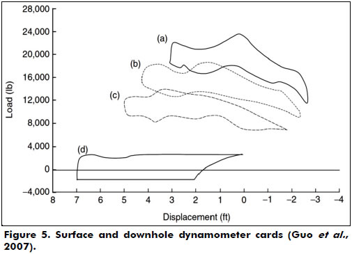
This article aims to study the rod string's behavior in wells equipped with an artificial lift system by a sucker rod pump. The numerical solution of the transient wave equation that heads the problem with appropriated initial and boundary conditions was obtained by using finite differences and implemented through a computational code in Matlab®. The outputs of the computational modeling are the surface dynamometer cards, SDCs, and the downhole dynamometer cards, DDCs (Figure 5). These cards constitute an important consolidated tool that helps in the control of the pumping system by diagnosing the operational conditions of the downhole pump (Ordoñez, 2008).
An SDC is a chart that shows the charge variation that operates in a polished rod during its displacement in the pumping cycle. An installed dynamometer between the clip and pump unit's table, on the surface, allows the registration of active forces in the polished rod at the top of the rod string during its displacement.
The DDC is a graphical representation of the effects generated by active forces in a downhole pump after propagation on a rod string. The elastic rod string behavior influences the effects generated in a downhole pump. For that reason, the SDC does not represent the actual downhole pump's behavior. Thus, to obtain a DDC, one can utilize special tools at the bottom of the well or use the mathematical models that calculate them from the SDC.
If the DDC shows a rectangle on the chart, that indicates the ideal conditions of pumping. Therefore, a hard and inelastic rod string with a low speed of pumping (which eliminates dynamic forces), incompressible pumped fluid and anchored rod tube are also ideal conditions. All energy losses along the rod are undesirable.
Figure 5a presents a typical SDC from a strain-gage type of dynamometer measured from a conventional unit operated with a 74-in stroke at 15.4 strokes per minute (spm). The peak load is 22,649 lb at the top of the 1 in rod. In Figure 5b, the peak load is 17,800 lb at the top of the 7/8 in rod. In Figure 5c, the peak load is 13,400 lb at the top of the 3/4 in rod. In Figure 5d, the DDC is at the plunger. This DDC indicates a gross pump stroke of 7.1 ft, a net liquid stroke of 4.6 ft and fluid load of 3,200 lb. The shape of the DDC also indicates some downhole gas compression and that the tubing anchor is holding properly. The negative load value in Figure 5d is due to the buoyancy of the rod string (Guo et al., 2007).
Methods
Physical model
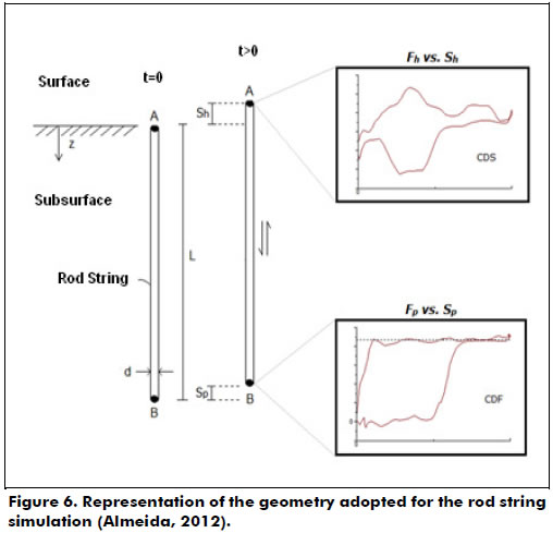
Adopted geometry consists of an ideal vertical rod string without gloves and without centralizers, of length L and diameter d constants. The rod has an alternative motion inside the fixed tubing. The positions represented by A and B points are, respectively, the connections with a polished rod (on the surface) and with a downhole pump (on the subsurface) (Figure 6). At these points, boundary conditions are applied in order to complete the mathematical formulation in which the solution describes the rod string's behavior: (i) A: kinematic of pump unit and (ii) B: operation of the downhole pump.
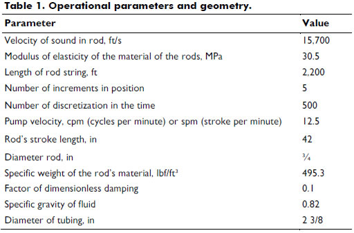
Sucker rod pump systems utilize a rod string to transmit an alternative surface motion to the downhole pump. Rods are steel tubes - they also can be made of fiberglass with an average length of 9 m and a diameter between 5/8 in (1.5875 cm) and 1 in (2,54 cm). They have connection gloves at each end, which allows for linking to other rods and forming a rod string with a total length that can be over 1,000 m. The input data related to the geometrical and operational features of the system and required to start the iterative process are shown in Table 1.
Mathematical model
The governing equation is described as a function of the analysis of active forces in the rod string. Figure 7 shows the active forces in a long element of the rod string in an upward motion.
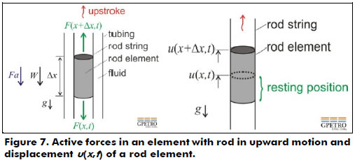
The element has a cross-sectional area A constant. At time t, the variable x represents any point in the rod string, and Δx is the displacement starting from this point. T(x+Δx,t) and T(x,t) are the traction forces in both boundaries of the differential element, which are related to the sections above and below the element. W is the rod element's weight, Fa is the fluid's damping force in the annular space rod string/tubing that opposes the rod string, g is gravity, and v is the element's velocity.
From the rate of change of its linear momentum in an inertial referential frame, it follows that
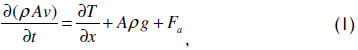
whereas the damping force is approximated by the product of the rod string's velocity v and a constant k, Fa = -kv. The negative exponent is due to the velocity of the rod being positive in the direction of motion, while the damping must act in the opposite direction, ρ is a constant density, and t is the time. Figure 5 also shows a draft of the displacement u of a differential element length Δx as a function of the position x of the rod string from a starting position u(x,t) to another position u(x+Δx,t) along the upward motion. Hooke's law, which is valid for the behavior of the elastic region, can be written as T = EA ∂u/∂x, where E is the modulus of constant elasticity or Young's modulus and A is the cross-sectional area of the rod. A constant should be assumed for A, which implies that changes in the area of the gloves and centralizers were not considered. The velocity of the rod can be obtained by the variation of a position in time, v = ∂u(x,t)/∂t.
Finally, if the cross-sectional area A of the rod, Young's modulus E of the material, and the density of material ρ and k are constant, equation (4) can be rewritten as
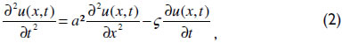
which is a one-dimensional transient partial differential equation of a second order known as the one-dimensional wave equation with viscous friction. The solution returns to the displacement u of a point x of the rod and time t. This equation, without gravitational effects, was initially presented by Gibbs in his pioneering work in 1963.
The damping factor portrays irreversible energy losses during the operation of the pump unit. According to Takács (2002), although these losses are derived from several varieties of complex phenomena, the effects are commonly considered to be of a viscous nature only. Gibbs (1963) stated that the damping factor is defined as ç = πac/(2L), where c is the dimensionless damping factor, which can be found through field measurements, and L is the length of the rod string.
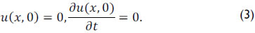
To complete the mathematical formulation, the initial condition and boundary conditions are needed. As an initial condition, that is, at time t = 0, the system is considered at rest and mathematically represented by equation (3).
The boundary conditions are applied at the ends of the rod string.
(i) Through the polished rod position on the surface, the simplest and most common approach that describes the rod string's motion is an assumption of a simple harmonic motion. Thus, considering Figure 2, the construction of a surface dynamometer card (SDC) consists of plotting the active charges on point A as a function of the motion of a polished rod. Equation (4) expresses the surface motion Sh(ϑ) of a polished rod using a crank angle (θ) (Takács, 2002).
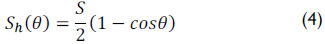
where S represents the stroke length of polished rod.
Construction of a downhole dynamometer card (DDC) must be plotted with the active charge in the position represented by point B in Figure 6 as a function of the plunger motion. For low velocities of pumping, the difference between the stroke length (Sh) of the polished rod and the length of the plunger (SP) is the sum of tubing stretch (et) and the rod string stretch (er), which occurs during the pumping process as shown in equation (5) (Takács, 2002)

The application of Hooke's Law allows for the determination of the tubing (non-anchored) and rod string stretching, represented by

where Fo is the fluid weight above the plunger and Et and Er are the elastic constants of tubing and rod material, respectively.
(ii) On the subsurface and at the operational conditions of the pump, Gibbs (1963) is represented by
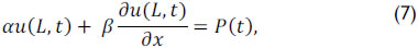
where α, β e P(t) depends on the type of pump operation which is being simulated and L is the length of the rod string.
For further details regarding the mathematical formulation briefly presented, we suggest consulting Doty and Schmidt (1983), Schmidt and Doty (1989), and Adams (2012).
Numerical model
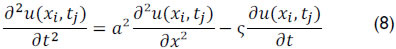
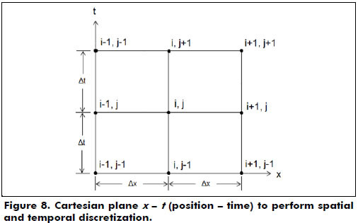
The rod string, regarded as one-dimensional and schematized in Figure 6, was segmented in the context of spatial discretization in various small parts as shown in Figure 7. The wave equation represented by equation (2), along with the initial and boundary conditions, equations (3), (4), (5) and (6), that govern the deformation of the rod string, was discretized by a finite differences method. The computational simulation of physical processes obtains time-dependent solutions of partial differential equations.
Discretization of the temporal terms was performed using an explicit method. In this approach, the unknown displacement at time instant n+1 is represented by u(x,t)n+1, or u(xi,tj+1), and the known variables, at time n, represented by u(x,t)n, or u(xi,tj).
The continuous equation, equation (2), is evaluated in discrete points (xi, tj), shown in Figure 8, resulting in
An approximation by finite differences for each of the three terms of equation (8) results in
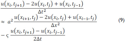
for i = 0,1,2,..., N-1 and j= 0,1,2,...,M-1.
Putting unknowns tj+1 in terms of tj and tj-1, equation (9) can be rewritten by isolating the term , resulting in
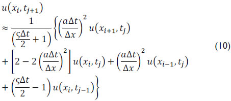
Thomas (1995) presented the CFL - Courant-Friedrichs-Lewy condition in order to obtain solutions for these discrete equations, which creates a dimensionless number known as the Courant number (Nc)
where a is the wave velocity, Δt is the time interval, and Δx is the size of the mesh element. The CFL condition states that for the method to be stable, the Courant number should be less than or equal to one. Thus, adopting NC = 1 it can be said that  . Therefore equation (10) can be simplified to

where A, B and C are constant defined by
Note that equation (12) provides a solution for in terms of three points (xi+1,tj), (xi-1,tj) and (xi,tj-1). Details are referenced in Doty and Schmidt (1983) and Schmidt and Doty (1989). In addition, it is necessary to write the initial and boundary condition in discrete form (Almeida, 2012).
The resulting discrete equations were implemented in Matlab® because the software has libraries that facilitate iterative calculations in space and time and provides a better graphical display of dynamometer card results.
The counterweight's constant angular velocity was assumed for the numerical simulation. With no gas interference, the pump is completely filled by the fluid and the fluid inertia is disregarded. Finally, the input data required to start the iterative process are shown in Table 1.
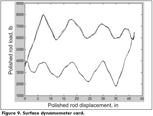
Results and discussion
Figures 9, 10 and 11 present the results of numerical simulations performed with the data listed in Table 1. The surface dynamometer card (Figure 9) shows the load in the polished rod based on its position. From this card, it was possible to obtain several operating parameters from the system. The maximum (PPRL - Peak polished road load) and minimum loads (MPRL - Minimal polished road load) on the polished rod were 8,002 lbs and 1,774 lbs, respectively. It was also possible to calculate the maximum torque that would be required of the gearbox's output shaft when moving.
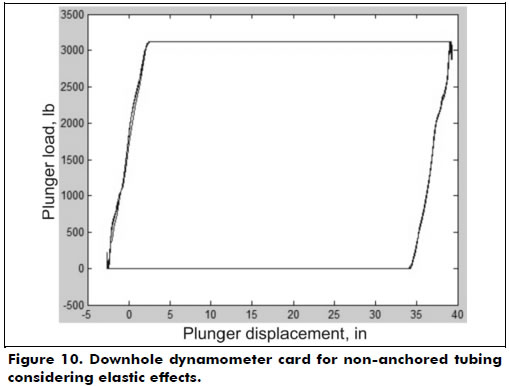
As previously mentioned, a downhole dynamometer card shows the active load on the subsurface plunge. Figure 10 illustrates a downhole dynamometer card with non-anchored tubing. In addition to the elastic behavior of the tubing, the elastic behavior of the rod string shows the card has assumed the shape of a parallelogram, i.e., the charge transfer from the standing valve to the traveling valve in the upward motion and the charge transfer from the traveling valve to the standing valve in the downward motion occurs gradually as a function of the rod's elongation.
Figure 10 was obtained by plotting the load on the piston by function of the plunger stroke represented by equation (5). Once the effective piston stroke length Sp is calculated by equation (5), it is possible to obtain volumetric displacement of the downhole pump (PD). Assuming that the pump barrel is completely filled with fluid during all the cycles, this displacement can be expressed by where N is the pump velocity and Ap is the transversal area of the piston (square inches) of 2 1/4 in diameter.
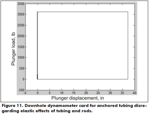
If the elastic effect did not exist, i.e., if the stretching of equation (5) were equal to zero, then the card would present a rectangular shape, as plotted in Figure 11.
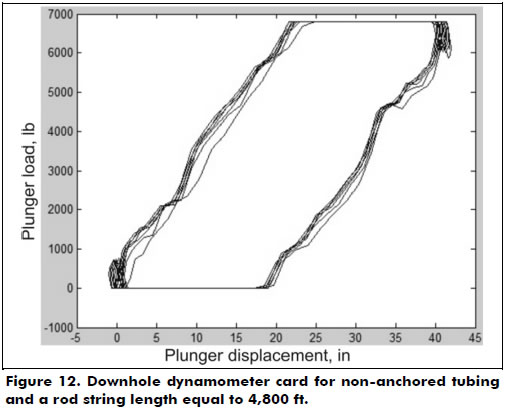
Figure 12 shows a variation of the downhole dynamometer card presented in Figure 10, increasing the total length of the rod from 2,200 ft (671 m) to 4,800 ft (1,463 m). When compared to Figure 10, it is observed that the result of Figure 12 shows a more pronounced stretching and a greater distortion of calculations in upward and downward motions. This is due to the increased size of the new rod string. According to Gomes (2009), distortions of the surface card from the propagation effect generated by the rod string may result in an inefficient analysis in certain cases. This problem is further aggravated by increasing the depth of wells past 3,280 ft (1,000 m).
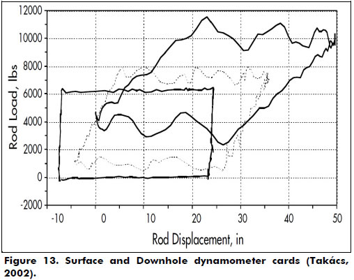
In order to qualitatively verify the validity of the computational code implemented, the results were compared to those of Tackács (2002), and the calculations of the surface dynamometer (SDC) and the pump (DDC) cards by the FINWAVE1 computer program are presented in Figure 13. The software performs a diagnostic analysis of the pumping system using the finite difference solution of the wave equation for a pump setting depth of 3,000 ft, dynamic liquid level of 3,000 ft, measured productive rate of 198 bpd, liquid specific gravity of 1.0, plunger size of 2.5 in, stroke length of 50 in, pumping speed of 9 spm, anchored tubing, pumping unit API size C-228-213-120, rod string steel of 0.31 psi, Young's modulus 3/4 in, 1.956 ft and 5/8 in 1.044. A qualitative comparison with Figures 9 and 10 corroborates our results.
Conclusions
This work presents the mathematical formulation of the Gibbs wave equation (1963) to predict the behavior of a sucker rod pump system, as well as the methodology for implementing an academic, non-commercial code that can simulate the behavior of the rod string through the generation of downhole and surface dynamometer cards in ideal pumping conditions. Appropriate initial conditions and surface and bottom-hole boundary conditions are considered in order to apply the finite difference technique to numerically solve the proposed problem.
Calculation of the downhole card consists of finding the charge immediately above the downhole pump from the surface data, and thus inferring operating conditions at the bottom of the well.
The simulation performed portrays the comparison of the downhole dynamometer cards in two cases. The first case is the elastic behavior of the rod string and the non-anchored string, and the second disregards such effects. The results are promising because they represent the expected behavior, according to the literature, of the dynamometer card for the simulated cases.
For future proposals, the implemented code will be the basis for the development of a simulation of more complex sucker rod pump systems. Other situations not considered in this study can dramatically alter the shape of the card, such as the presence of dynamic charges on the rod string, the fluid compressibility, non-Newtonian viscosity, induction of stress waves in the rod string and any operational problems (lack of synchronization of the valves, blow fluid, gas interference, among others).
The Gibbs damping factor (1963) was used in this study, which presents a problem for estimating the value of the dimensionless damping coefficient for new wells. Moreover, these coefficients are different during the upstroke and downstroke, which Gibbs did not consider. This simplification was used, but a more comprehensive model has been proposed by Lea (1990) for a damping term that takes into account the viscosity of the fluid and the diameters of the plunger, tubing and rods.
An important consideration is the incorporation of various geometries of the pump unit, which can change boundary conditions at the surface. Substituting the consideration of a simple harmonic motion by a kinematic analysis of pump units allows for calculation of the polished rod's position as a function of the crank angle according to pump unit geometry.
Another proposal is the adaptation of the code to enable the simulation of cases such as a combined rod string, deviated wells and consideration of the annular level from the background knowledge in the bottom hole pressure.
Acknowledgements
We are grateful to Jean Carlos Dias de Araujo and Gelson Heraldo Nico Filho, professionals at Petrobras SA, for their helpful technical comments during the development of this work. Professor Oldrich Joel Romero thanks the National Council of Technological and Scientific Development (CNPq) and "Fundação de Amparo à Pesquisa do Espírito Santo" (FAPES). Also our thanks go to Ms. Connie Galt, Chemical Engineering and Materials Science, University of Minnesota, for her valuable comments.
References
Almeida, P. (2012). Previsão do comportamento de sistemas de bombeio mecânico (in Portuguese). Graduation Project. Federal University of Espirito Santo. São Mateus, ES, Brazil. [ Links ]
Bellarby, J. (2009) Well Completion Design. Jordan Hill, OX: Elsevier (DPS 56). [ Links ]
Chevelcha, E., Langbauer, C. J., & Hofstaetter, H. (2013). Listening Sucker Rod Pumps: Stroke's Signature. SPE 165035-MS. SPE Artificial Lift Conference - Americas, May 21 - 22, 2013, Cartagena, Colombia. [ Links ]
Clegg, J. D., Bucaran, S. M., & Hein Jr., N. W. (1993). Recommendations and Comparisons for Selecting Artificial Lift Methods. Journal of Petroleum Technology, SPE 24834-PA, 45(12), 1128-1167. [ Links ]
Doty, D. R., & Schmidt, Z. (1983). An improved model for zucker rod pumping. SPE Journal, 23(1), 33-41. dox: 10.2118/10249-PA. [ Links ]
Economides, M. J., Hill, A. D., & Ehlig-Economides, C. (1994). Petroleum production systems. Upper Saddle River, NJ: Prentice Hall. [ Links ]
Gala, R. D. (2013). Preventing Gas Locking in Sucker Rod Pumps Using an Actuated Traveling Solenoid Valve. SPE 165039-MS. SPE Artificial Lift Conference - Americas, May 21 - 22, 2013, Cartagena, Colombia. [ Links ]
Ghareeb, M., & Beck, A. (2012). Design of Sucker Rod Pumping Systems for Effectively Handling Solids and Sand. SPE 157126-MS. SPE International Production and Operations Conference & Exhibition, 14-16 May 2012, Doha, Qatar. [ Links ]
Gibbs, S. G. (1963). Predicting the Behavior of Sucker-Rod Pumping Systems. Journal of Petroleum Technology, 15(7), 769-778. doi: 10.2118/588-PA. [ Links ]
Gomes, H. P. (2009). Desenvolvimento de um sistema inteligente para a análise de cartas dinamométricas no método de elevação por bombeio mecânico (in Portuguese). Master's Dissertation. Federal University of Rio Grande do North. Natal, RN, Brazil. [ Links ]
Guo, B., Lyons, W. C., & Ghalambor, A. (2007). Petroleum Production Engineering: A Computer-Assisted Approach. Burlington, MA: Gulf Professional Publishing. [ Links ]
Jiménez, H. M. G., Naranjo, J. E. C., & Pérez Herrera, R. (2013). Results From Annular Injection in Heavy and Extra Heavy Oil Wells Producing With Rod Pumping in the Samaria Field: A Field Test. SPE 65069-MS. SPE Artificial Lift Conference - Americas, May 21 - 22, 2013, Cartagena, Colombia. [ Links ]
Lea, J. F. (1990). Modeling forces on a bean pump system when pumping highly viscous crude. SPE Production Engineering, 6(4), 420-426. doi: 10.2118/20672-PA [ Links ]
Ordoñez, B. (2008). Proposta de controle de operação de poços com bombeio mecânico através da pressão de fundo (in Portuguese). Master's Dissertation. Federal University of Santa Catarina. Florianopolis, SC, Brazil. [ Links ]
Schmidt, Z., & Doty, D. R. (1989). System Analysis for Sucker-Rod Pumping. SPE Production Engineering, 4(2). doi: 10.2118/15426-PA. [ Links ]
Suling, W., Tiejun, W., Gao, Y., & Ying, L. (2013). Analysis and Countermeasures on the Efficiency of the Pumping Wells System in the Old Oil-field. SPE 165861-MS. SPE Asia Pacific Oil and Gas Conference and Exhibition, 22-24 October 2013, Jakarta, Indonesia. [ Links ]
Takács, G. (2003). Sucker-rod pumping manual. Tulsa, Oklahoma: PennWell Books. [ Links ]
Thomas, J. E. (Ed.) (2004). Fundamentos de engenharia de petróleo (in Portuguese)(2nd ed.). Rio de Janeiro: Editora Interciencia. [ Links ]
Thomas, J. W. (1995). Numerical partial differential equations: Finite difference methods. New York, NY: Springer-Verlag. [ Links ]
