


Services on Demand
Journal
Article
 English (pdf)
 Article in xml format
 Article references
 Send this article by e-mail
Indicators
-
 Cited by SciELO
 -
 Access statistics
Related links
-
 Cited by Google
 -
 Similars in
SciELO
Similars in
SciELO -
 Similars in Google
Share

 Permalink
Ingeniería e Investigación
Print version ISSN 0120-5609
Ing. Investig. vol.35 no.1 Bogotá Jan.Apr. 2015
https://doi.org/10.15446/ing.investig.v35n1.44995
DOI: http://dx.doi.org/10.15446/ing.investig.v35n1.44995
G. P. Heckelsmueller1
1Gregor Paul Heckelsmueller. Renewable Energy Engineering B.Sc., University of Stuttgart, Germany. Affiliation: University of Stuttgart, Germany. E-mail: gregor.heckelsmueller@t-online.de
How to cite: Heckelsmueller, G. P. (2015). Application of variable speed operation on Francis turbines. Ingeniería e Investigación, 35(1), 12-16. DOI: http://dx.doi.org/10.15446/ing.investig.v35n1.44995
ABSTRACT
Francis turbines that are directly coupled to a synchronous generator operate at constant rotational speed around a design point characterized by a given water head, flow and guide vane aperture. When important changes occur in headwater level in power stations with large reservoirs, the turbines suffer a significant loss of efficiency. By applying variable speed technology it may be possible to adapt the runner speed and to operate with a higher efficiency over a wide range of water heads. This investigation is intended to reveal the possible benefits of using variable speed operation in regard to gains in efficiency and power output.
Based on model test data it is possible to determine the characteristic curves of unitary speed and unitary flow of the respective prototype turbine for varying guide vane apertures. By varying rotor speed it is possible to maintain values that correspond to maximum efficiency. An analysis is made keeping guide vane aperture constant and introducing a proportionality factor of water flow to corresponding power output. The results show that for guide vane apertures and heads different from the design point, best efficiencies can be kept by adjusting rotor speed. At heads lower than the design head, significant efficiency gains can be achieved. Consequently, a significant proportion of the flow can be saved while generating the same amount of power.
Keywords: Hydropower, Francis turbine, turbomachinery, variable speed, double-fed asynchronous machine, water head, unitary speed, unitary flow.
RESUMEN
Las turbinas Francis están acopladas directamente con sus generadores síncronos. Debido a esto la geometría de sus turbinas está diseñada para operar con velocidad sincrónica en un punto característico que corresponde al salto y el caudal de diseño con una respectiva apertura de los álabes. Para otros saltos mayores o menores al de diseño y sus correspondientes caudales la eficiencia será menor que la máxima esperada en el punto de diseño.
En este trabajo se investiga la posibilidad de mantener la turbina operando en el punto de mejor eficiencia mediante la variación de la velocidad. La investigación demuestra la posibilidad de obtener beneficios aprovechando la velocidad variable en cuanto a la eficiencia y la potencia útil. Se obtienen de las pruebas de modelo las curvas características de velocidad unitaria y caudal unitario, tanto del modelo como del prototipo para diferentes aperturas de los álabes. Gracias a la velocidad variable es posible mantener los valores correspondientes a la mayor eficiencia. Se analizan para aperturas fijas de los álabes los aumentos de eficiencia para el rango de saltos y se introduce un factor de correlación entre caudal y potencia. Para saltos inferiores al de diseño, se pueden obtener aumentos de eficiencia y ahorros de caudal significativos generando la misma potencia.
Palabras clave: Energía hidroeléctrica, turbina Francis, turbomáquina, velocidad variable, generador doblemente alimentado, salto, velocidad unitaria, caudal unitario.
Received: August 15th 2014 Accepted: January 6th 2015
Introduction
Francis turbines are the most common water turbines in use today. The turbines are generally connected by their shaft directly to a generator, which is itself connected to the electric grid. The mechanical rotational energy of the turbine is converted by the generator into electric energy. In nearly all cases the generators used are synchronous machines because of their great advantages producing voltage and frequency of the grid and providing reactive power for consumers and network. Due to its direct connection to the grid the generator's rotor spins at a constant speed, the frequency of the grid. Equally, because of its direct coupling the turbine's runner spins with this same rotational velocity. This configuration is subsequently referred to as “conventional”.
Typically Francis turbines are designed for operation at a constant speed around a best operation point characterized by head, discharge and guide vane aperture. If one of these parameters change and the turbine operates at an off-design operation point it may suffer a significant efficiency loss at any guide vane aperture. Due to operation at off-design water heads, changes can occur in the velocity triangles of the inlet and exit flow. At the inlet to the rotor blades shock losses may occur and flow instabilities at the exit provoke further drops in efficiency. The guide vane position has a direct effect on the inlet velocity. Therefore this investigation studies the effect on the efficiency of the application of variable speed technology on a single Francis turbine. By influencing the rotor velocity the flow velocity triangle may be adapted to operate at different water heads with less efficiency losses. Furthermore it evaluates if it is possible to quantify the benefits of variable speed technology with data provided by typical turbine model tests. As the tests are performed by the turbine manufacturer in any case, it would be a great advantage if the benefits of installing a variable speed system or retrofitting such a system in an existing turbine-generator set could be evaluated with the data provided by the manufacturer. A method of analysis is described and applied to the data set.
Several investigations concerning the influence of variable speed technology on hydro power turbines have already been carried out. Fraile-Ardanuy et al. evaluated the advantages of applying variable speed technology on hydro generation regarding turbine, generator and control system. A gain of 6.5% of average annual energy output and several environmental benefits are discovered. Farell et al. illustrate the effects of variable speed design as a flow control device. Furthermore possible efficiency augmentations are investigated, both for fixed-blade, fixed-vane turbines and turbines with wicket gates and adjustable blades. For Francis turbines a decreasing flowrate Q was found for increasing speeds and constant guide vane aperture and water head. However, no improvement of efficiency was registered for constant heads and off-design flows. Campos Barros et al. examined three advantages of operating over a range of speed for Francis, Kaplan and propeller turbines: environmental benefits, energy gains and avoidance of cavitation. In the case of Francis turbines a slight average energy increase is found with a variation of frequency of up to ±20% being necessary. Additionally it shows that operation points prone to cavitation could be reduced or even avoided by variable speed technology.
As cavitation and similar secondary effects such as vibrations depend on head, aperture and rotational velocity, varying the rotor speed strongly influences the cavitational limits given in conventional operation. Therefore in this investigation, heads beyond these limits are also considered even though in conventional operation it is not recommended to operate the turbine in this manner.
The Francis turbine studied in this research has a 2.37 m diameter and 20 rotor blades. It is located at 306m (MSL) and operates at a range of water heads of 357.60 m to 282.00 m with a 322.00 m nominal head. Corresponding power outputs are from 147.5 MW up to 210 MW with a nominal power output of 184 MW. These conditions give the specific speed ns of 112.59 kWm. At its design point of 322 m and with a nominal aperture of 178 mm the turbine operates with Q =61.17 m³/s.
Variable speed generator technology
In order to change the runner speed, the rotor velocity of the generator has to be variable. There are several technical solutions to do this. These solutions normally suffer from high additional costs, as they provide full-scale conversions, i.e. provide operation at any frequency. But as only a limited change of the rotor speed would be necessary, a less expensive doubly fed induction generator (DFIG) and a power electronic converter with a lower converter rate in comparison to total machine rating is the most promising alternative. As DFIG are already very common in wind generators, technology to vary rotor speed in generators is both available and fully developed. Other advantages are a better reactive power handling and therefore a contribution to grid stability.
The stator is directly connected to the grid. The rotor in contrast gets its voltage and frequency from an electronic power converter. It introduces a slip frequency AC field current, thereby allowing the rotor to spin faster or slower than the grid frequency. Normally this change accounts for up to ±30% of the original frequency. As the DFIG rotor is directly connected by the shaft to the turbine runner, it is possible to vary the turbine speed.
Model test and data source
In hydraulic turbine engineering analytical calculations of efficiency and other effects on the turbine are difficult or impossible. Even though digital computer models and numeric calculations are well developed, comprehensive digital simulations are expensive and lack accuracy. Therefore model tests are important to examine the characteristics of a turbo machine experimentally. A scaled down model of the latest prototype was tested according to IEC 60193. Using similarity laws, the results of these model tests are converted to non-dimensional form and valid for all turbines that are geometrically similar to the model. The examined model has a diameter of 0.36 m. While the runner speed of the model is variable, the prototype has a fixed speed nP of 360 rpm.
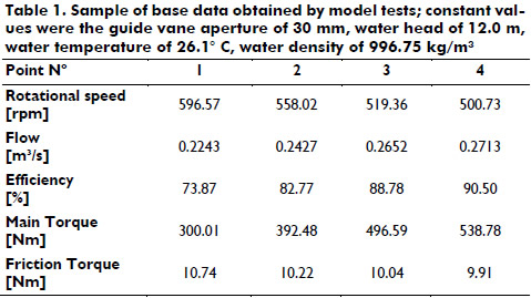
The model tests evaluate turbine behavior amongst others in efficiency terms. Thus, the rotational speed and the guide vane aperture of the turbine model were altered keeping the water head constant. The resulting data consists of 15 data sets for each guide vane aperture varying flow. Some base data of this examination is illustrated in Table 1. The torque resulting on the shaft was measured by a Prony brake. Hereby, brake pads slow down the axis. The torque equals a lever arm that actuates the pads times the applied force at its end. Losses due to bearing friction along the shaft were given as frictional torque. The total torque uncertainty is given as 0.081%, which consists of systematic uncertainty and repeatability.
According to IEC 60193 overall maximum experimental inaccuracies account for 0.1% due to random errors. At least five measurements were taken of one predefined point to verify the deviation.
Evaluation of data and approach of analysis
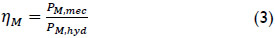
The efficiencies for different flows are obtained by a comparison of mechanical output power and hydraulic power. Subscripts “M” below refer to the turbine model. The mechanical output power PM,mec is defined as:

with rotational speed nM and torque TM. The hydraulic power PM,hyd is:

with discharge QM, water head HM, density ρ and acceleration due to gravity 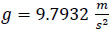 for test conditions on-site.
Consequently, the efficiency results as:
Due to different fluid dynamic conditions, the Reynolds number ReM during the model test was lower than the constant Reynolds number of the model ReM* = 7x10⁶. Therefore higher losses occurred during the test and the efficiency has to be scaled up in a first step to the reference conditions of the model according to IEC 60193. The standard defines the Reynolds number of reference as: Reref = 7x10⁶.
The scale-up formula for the efficiency ηM* corresponding to the constant Reynolds number of the model is given as:

with ηM being the model efficiency and:
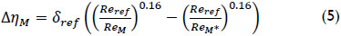
The scalable losses are defined as:
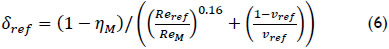
with loss distribution coefficient vref which is the ratio of relative scalable losses to relative total losses. For a Reynold number of reference 7x10⁶, vref is 0.7 for Francis turbines according to IEC 60193. The Reynolds number during the tests is given as:
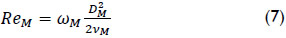
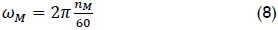
with model diameter DM, the angular velocity:
and the kinematic model viscosity:
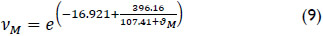
ϑM is the arithmetic mean of the water temperature during the test of each guide vane aperture.
In a second step the efficiency has to be scaled up to the hydraulic conditions of the prototype according to IEC 60193. The step up to prototype conditions is defined as:

with:
The prototype Reynolds number is given as:
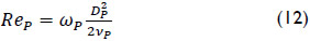
with prototype diameter DP, the angular velocity of the prototype:
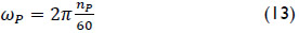
and the kinematic prototype viscosity:
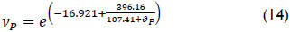
ϑP is the water temperature of the prototype, determined as ϑP = 22.5oC. According to IEC 60193 the transposition of formulas (4) to (14) includes a maximum error of 0.27%.
The results of the efficiency tests are transformed into unitary discharge Q11 and unitary rotational speed n11 by:
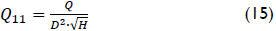
with being the turbine diameter and by:
Q11 and n11 are non-dimensional figures that are unique to each set of similar turbines at a specific guide vane aperture. In theory, they correspond to a turbine with a 1 m diameter and a 1 m head. Q11 and n11 depend on each other and form characteristic curves for a given guide vane aperture. By means of model turbine tests it is possible to find for every test point its Q11-n11-pair of value and the corresponding efficiency. For a given guide vane aperture, the maximum efficiency point is clearly characterized by its Q11 and n11-values. Consequently, the turbine is operating with maximum efficiency if it shows these unitary values.
For any turbine operation point in fixed speed mode, it is possible to determine its corresponding values of Q11 and n11 according to equations (15) and (16). If the turbine is not operating in its design point, a difference Δn11 exists between the n11,conv in conventional operation mode and its value n11,η=max in the maximum efficiency point:

In order to compensate for this difference and to operate with n11,η=max, the current value n11,conv has to be changed. Considering equation (16) an intended change of n11 has to be carried out by a change of speed using variable speed technology as D is geometrically constant and H is forced by external conditions. Therefore the necessary speed change ΔnP of the prototype, in order to operate with n11,η=max, results as:

A rotational speed change provokes a discharge change. As it can be evidenced in equation (15), changing Q also changes Q11 as D and H remain constant. Therefore n11 and Q11 correlate and form a pair of values.
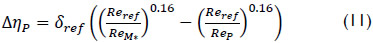
The difference ΔηP of the efficiencies ηconv for operation mode at conventional speed and ηmax under variable speed drive is:

As model tests only offer discrete data, spline interpolations are made to obtain continuous gradients of Q11, n11 and efficiency. Any head within the limits of operation is investigated for every examined guide vane aperture. For discrete head 0.5 m steps the corresponding value of n11 is calculated and the nearest maximum of efficiency found. In the case of “no maximum at all” the local maximum at the edge of the limits is chosen. Apart from the differences (17) to (19), corresponding discharges in conventional operation mode Qconv and in variable speed operation mode Qη=max are calculated. Derived from equation (15) they are given as:

and

depending on the head H.
Furthermore it is possible to obtain the power output difference of the prototype turbine in conventional operation and at maximum efficiency operation. Conventional power output is defined as:

power output at maximum efficiency is defined as:

Moreover, a discharge-to-power factor is defined for both constant and variable rotational speed mode and according to:
F shows directly the consequences of the higher efficiency by demonstrating how many m3/s are necessary to produce one megawatt.
Results
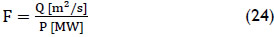
In order to generalize results, all figures are made of non-dimensional referring values to their corresponding nominal value, i.e. heads are referred to the design head, speed to design speed. Operating at these design values, the turbine shows maximum efficiency with the nominal guide vane aperture. To approach the real continuous distribution of guide vane apertures, discharges and power outputs are spline interpolated over the range of aperture. The maximum guide vane aperture is 197.7 mm, the minimum is 66.0 mm. Figures are presented for nominal guide vane aperture of 134 mm, for an aperture of 178 mm and for the technical maximum of 197.7 mm. The first two sets are based on interpolated data.
Figure 1 shows the curves of maximum efficiency for conventional operation mode and for variable speed operation mode and the rotor speed necessary for the latter.
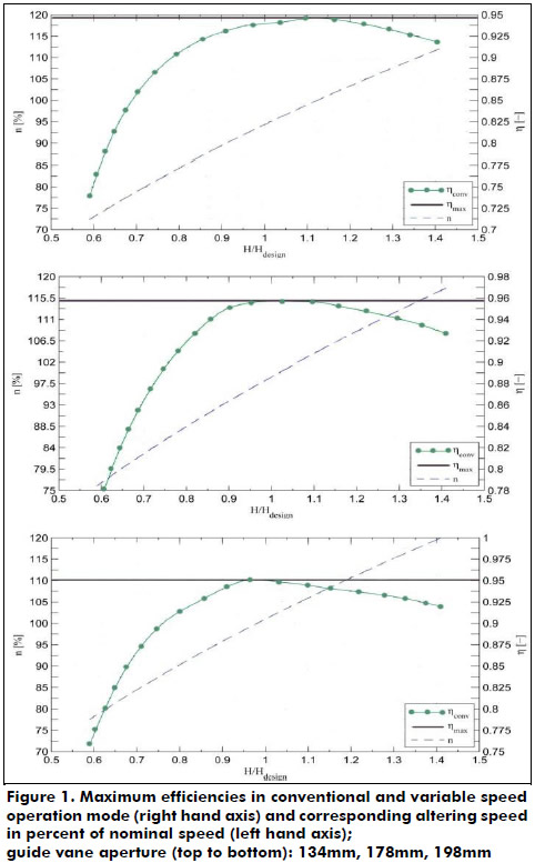
Figure 2 shows the corresponding discharge-to-power relations in conventional and variable speed operation.
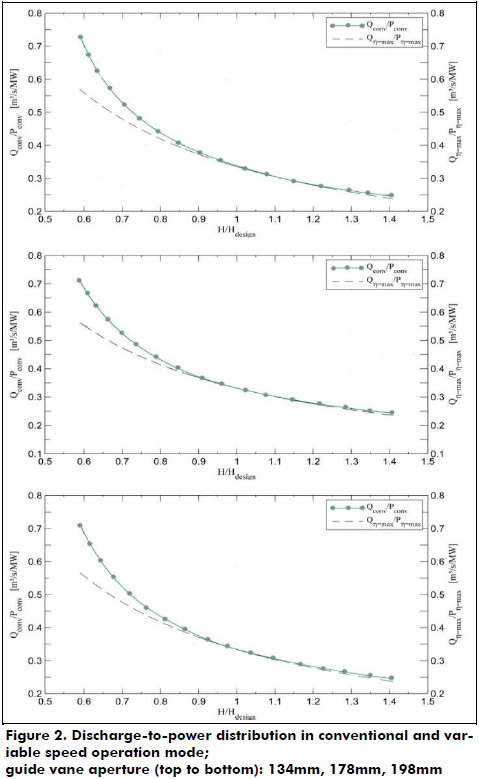
The following descriptions are made for the analysis of the nominal guide vane aperture of 178 mm and refer to the middle graphs of Figure 1 and Figure 2. As expected, the efficiency curves coincide at the turbine's design point at H/Hdesign=1, Figure 1. Here the turbine achieves its highest efficiency of 95.75%. Away from this point, efficiencies fall rapidly in conventional operation especially for smaller heads than the design head. At 60% of the design head the turbine merely offers an efficiency of 77%, for a head 40% above design head efficiency drops to 93% (Figure 1). By applying variable speed technology it is possible to operate within a range of ±40% of design head with the maximum efficiency of 95.75%, assuming a nominal guide vane aperture. Above the design head an increase to 117.5% of conventional speed is necessary, below H/Hdesign=1 a reduction to 77.5% of conventional speed has to be done. Due to this speed adjustment it is possible to improve the turbine efficiency by 22% at a head of 40% less than the design head and by 3% at a head of 40% greater than the design head. The corresponding discharge-to-power relations as shown in Figure 2 coincide at the design point and diverge for heads above and below. That means that different heads from the nominal head consume less water to produce the same amount of power in variable speed operation than in conventional operation mode thanks to the increased efficiency. The difference is very small for greater heads than the design head. However, it becomes increasingly important for lower heads. For a head of 60% of the design head, it is possible to save up to 25% of discharge while offering the same power output. It is also worth mentioning that the corresponding discharge mode is generally influenced by speed variations as well. Increased speed of the Francis turbine causes a flow decrease, while a decrease causes an increased discharge. However, the augmentation of efficiency outweighs these effects. Below the design head efficiency gains are greater than discharge augmentations due to the lower speed generating 1 MW. Above the design head both effects combine and produce a reduced flow.
Comparing the figures of the nominal guide vane aperture with the ones given in Figure 1 and Figure 2 for an aperture of 75% and 111% several statements valid for all guide vane apertures can be done. The analyses of other guide vane apertures have corresponding results. The application of variable speed technology allows operating at any head with the highest possible efficiency corresponding to the actual guide vane aperture. By varying rotor speed the turbine returns to the optimum of its n11-Q11-curve operating at a maximum efficiency. At the design points no benefit is possible as the turbine already operates at its maximum efficiency. However, for heads less than the design head an application of variable speed technology has significant benefits for all apertures. Efficiency gains are remarkable and so are corresponding discharge savings while generating the same power output. For higher heads than the design head possible advantages of variable speed operation are marginal for all guide vane apertures.
Transferability and conclusions
Since in this example only one turbine data is examined the transferability of results has to be considered. The examined Francis turbine is used in a high-head hydropower plant, where distinctive changes of water head are less common. However, it shows the typical trend of efficiency of Francis turbines for varying heads.
The results allow several conclusions. Firstly, it is possible for most heads and most guide vane apertures to improve the Francis turbine's efficiency by applying variable speed technology. By varying the rotor speed, the best efficiency corresponding to the existing aperture can be exploited. However, the technology is best used if the actual water head lies below the design head at the applied guide vane aperture. A potential change of the aperture depending on reservoir water level should therefore be contemplated. Hereby a change of discharge due to speed variation and as a consequence a change of power output has to be considered. Consequently, no statement about recommended guide vane configuration for respective heads is possible, as desired discharge and power output depend strongly on the power plant operator. As a result, variable speed operation offers a multitude of new regulating and operating strategies for power plant operators, all of them utilizing an improved efficiency at any non-design operation point. This examination shows that speed variations of about ±20% of conventional speed are necessary to operate within a range of ±40% of the design head at maximum efficiency. As the efficiency curves of the evaluated turbine shows, a typical gradient no greater speed variation should be needed for Francis turbines in general.
An application of variable speed technology for Francis turbines is especially relevant for low-head turbines. Results show that the difference of maximum efficiencies in conventional and in variable speed operation increases for rising or falling heads. Analogous to diverging efficiencies, less discharge at constant power output is necessary using variable speed operation. As head variations in low head turbines compared to design head tend to be significant, efficiency gaps rise rapidly and advantages of variable speed design can be fully utilized. Moreover, this investigation shows that model tests are adequate for a first examination of variable speed operation.
Finally, explicit cavitation tests are necessary for variable speed operation. Conventional cavitation tests as done during model turbine test loops are not sufficient. Cavitation depends amongst others strongly on rotational velocity. Consequently cavitational limits should be different with variable speed technology.
References
Avellan, F. (2004). Introduction to cavitation n hydraulic machinery. Lausanne, Switzerlan: EPFL Swiss Federal Institute of Technology. [ Links ]
Campos-Barros, J. G., Saidel, M. A., Ingram, I., & Westphalen, M. (1996). Adjustable speed operation of hydroelectric turbine generators. ELECTRA, 167(August), 17-37. [ Links ]
Farell, C., & Gulliver, J. (1987). Hydromechanics of variable speed turbines. Energy Engineering, (133), 1-13. [ Links ]
Fraile-Ardanuy, J., Wilhelmi, J. R., Fraile-Mora, J. J., & Pérez, J. I. (2006). Variable-speed hydro generation: operational aspects and control. IEEE Transactions on energy conversion, 21(2), 569-574. [ Links ]
International Electrotecnical Commission IEC (1999). Standard 60193, second edition 1999-11. Hydraulic turbines, storage pumps and pump-turbines - Model acceptance tests. Geneva, Switzerland. [ Links ]
Simond, J.-J., & Schafer, D. (1998). Adjustable speed asynchronous machine in hydro power plants and its advantages for the electric grid stability. Lausanne, Switzerland. [ Links ]
