


Services on Demand
Journal
Article
 English (pdf)
 Article in xml format
 Article references
 Send this article by e-mail
Indicators
-
 Cited by SciELO
 -
 Access statistics
Related links
-
 Cited by Google
 -
 Similars in
SciELO
Similars in
SciELO -
 Similars in Google
Share

 Permalink
Ingeniería e Investigación
Print version ISSN 0120-5609
Ing. Investig. vol.35 no.2 Bogotá May/Aug. 2015
https://doi.org/10.15446/ing.investig.v35n2.45603
DOI: http://dx.doi.org/10.15446/ing.investig.v35n2.45603.
A novel finite element method for designing floor slabs on grade and pavements with loads at edges
Novedoso método de elementos finitos para diseñar losas para pisos industriales con cargas en los bordes o juntas
H. E. Camero1
1 Hugo Camero Sanabria. Civil Engineer, Universidad Nacional of Colombia, graduated Valedictorian of the class. Master Degree in Finances, Universidad de los Andes, Colombia. Awarded the "Merit in Construction" by the Association of Civil Engineers, Universidad Nacional of Colombia (AICUN). Currently, he is the manager of Construdiseños Ingenieros Arquitectos S. A., Bogotá, Colombia. E-mail: construdisenosai@hotmail.com, hecameros@unal.edu.co.
How to cite: Camero, H. E. (2015). A novel finite element method for designing floor slabs on grade and pavements with loads at edges. Ingeniería e Investigation, 35(2),,1 5-22.
DOI: http://dx.doi.org/10.15446/ing.investig.v35n2.45603.
ABSTRACT
In the present paper a methodology to design slabs on grade for industrial floors and pavements using bi-dimensional finite elements and integrating the subgrade in the design is presented. The suggested method to design slabs on grade for industrial floors and pavements has been called the Camero Finite Element Method. An example of an industrial floor designed to be capable of sustaining an infinite number of load applications (or a 50 years lifespan period) is here presented in order to be compared with the results of the Camero Finite Element Method, the PCA (Portland Cement Association), and the WRI's (Wire Reinforcement Institute) simplified methods. In this example, an industrial floor is designed to be capable of sustaining an infinite number of load applications comparing the results of the Camero Finite Element Method and the simplified methods of the PCA and WRI. The industrial floor or pavement will be able to resist an infinite number of load applications if it is designed with the Camero Finite Element Method. On the other hand, if it is designed using the PCA and the WRI methods, it will last a few years (in this example, in one year period, the number of axle load applications is equal to the number of allowable repetitions). To conclude, if an industrial floor o pavement is designed with the Camero Finite Element Method, it will be able to sustain an infinite number of load applications (up to 50 years lifespan period).
Keywords: Floor slab on grade, industrial floor slab, Portland Cement Association, wire reinforcement institute, slab design on grade, floor design, industrial floor slab, concrete floor, concrete slab on grade, pavement, rigid pavement, Camero finite element method.
RESUMEN
En el presente artículo se presenta una metodología para el diseño de losas sobre terreno para pisos industriales y pavimentos utilizando elementos Anitos bidimensionales e integrando el suelo en el diseño. El método propuesto para diseñar pisos industriales ha sido llamado Camero Finite Element Method. Un ejemplo de un piso industrial diseñado para soportar un número infinito de repeticiones de carga (o un periodo de vida útil de 50 años) es aquí presentado con el fin de comparar los resultados de Camero Finite Element Method, los métodos simplificados de la PCA (portland Cement association) y la WRI (wire Reinforcement Institute). En el ejemplo, un piso industrial es diseñado para ser capaz de admitir un número infinito de aplicaciones de carga (o un periodo de vida útil de 50 años), comparando los resultados de Camero Finite Element Method y los métodos simplificados de las PCA y la WRI. El piso industrial o pavimento será capaz de resistir un número infinito de aplicaciones de carga (50 años) si es diseñado con Camero Finite Element Method. De otra manera: Si es diseñado por los métodos de la PCA y la WRI únicamente durará pocos años (en este ejemplo, en el periodo de un año el número de aplicaciones del eje cargado es igual al número de repeticiones admisibles). Concluimos que el piso industrial o pavimento será capaz de admitir un número infinito de aplicaciones de carga (periodo de vida útil de 50 años) si es diseñado con Camero Finite Element Method.
Palabras clave: Losa sobre terreno, losa industrial, Portland Cement Association, Wire Reinforcement Institute, diseño de losas sobre terreno, diseño de pisos, placas de pisos industriales, losas de pisos industriales, pisos de concreto, pisos de concreto sobre terreno, pavimentos, pavimentos rígidos, método de elementos finitos de Camero.
Received: September 18th 2014 Accepted: June 16th 2015
Introduction
Designing slab floors on grade for industry consists in designing slabs for storage and traffic loads produced by vehicles and forklift trucks, these generally being the most critical. This article shows how the Portland Cement Association (PCA) and Wire Reinforcement Institute (WRI) simplified methods for designing slabs for forklift truck traffic, consider the bending moments applied to slabs smaller than those presented under operational conditions by forklift trucks being misaligned with the slab's longitudinal axis centre (eccentricity between slab centroid and the centre of the forklift's truck loaded axle).
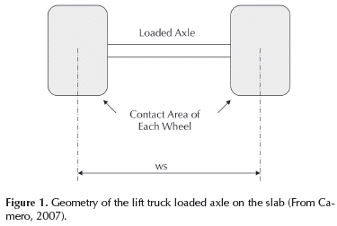
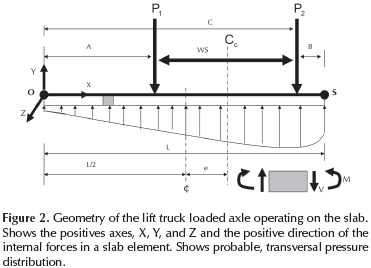
Figure 1 shows the geometry of the forklift's truck loaded axle. WS is wheel spacing of the forklift truck's loaded axle. Figure 2 shows the loaded axle working on the slab. Theforklift's truck centre longitudinal axis has been called CC and the slab's centre longitudinal axis, has been called ¢.
The article explains the development a method to design slabs on grade for industrial floors and pavements with finite element analysis in two-dimensional problems including the subgrade. The terms for stresses are obtained on the assumption that the soil is a perfectly elastic material.
Analytical investigation
Stress due to load
The reduction of a three-dimensional problem to a two-dimensional problem can occur in plane stress and plane strain. For each case, see Segerlind (1984) and Oñate (1995).
The state of plane stress occurs if a pavement has isolation joints, contraction joints and expansion joints. The stress components associated with the direction perpendicular to the plane of the applied loads, σzz, σzx, and σzy are very small and assumed to be zero, when the applied loads lie in the x-y plane.
The example showed in this article is limited to elasticity problems.
The generalized Hooke's law can be written as (and remember that σzz = 0, σzx, and σzy = 0):

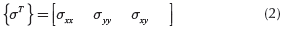
σ is the stress vector and can be written as:
The matrix D is (Linero and Garzón, 2010, chapter 5)
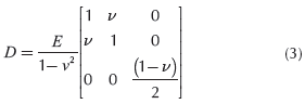
Where v is a constant calleds Poisson's ratio and E is the modulus of young or modulus of elasticity.
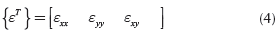
ε, the elastic strain vector is
The displacement equations
There are two unknown displacements in a two dimensional elasticity problem, μ and ν. The displacement parallel to the z-axis, ω, is related to μ and ν.
The μ and ν displacements are modeled in a continuum element by defining two displacement components at each node (Figure 3).
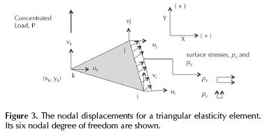
The linear triangular element is perhaps the earliest and simplest finite element. A resume of formulation in element finite is show below. The author recommends the readers to read Segerlind (1984) and Oñate (1995).
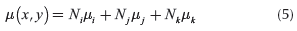
The horizontal displacement μ is approximated using:
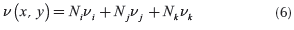
The vertical displacement component ν is represented by:
Utilizing matrix notation yields
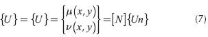
Where [N] is the matrix 2x6 that contains the element shape functions and {Un} is the vector that contains the element nodal displacements.
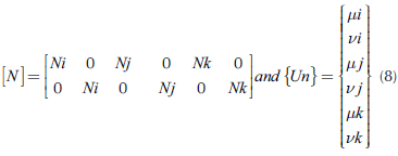
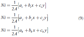
Ni, Ni and Nkare the linear shape functions that by a linear triangular element are (Segerlind, 1984, pp. 51-67):
The strain components and displacements are related. These relationships are called the strain-displacement equations and are derivated in all elasticity books (Linero and Garzón, 2010 and Timoshenko and Goodier, 1970). They are:
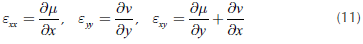
Using matrix notation, the vector strain with Equations (4),(5), (6), (7), (8), and Equation (11), is:
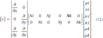
Using matrix notation, the Equation (12) can be written as:
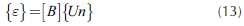
Equation (13) defines the gradient matrix [B] for the triangular element. It is a 3x6 matrix.
The linear triangular element shown in Figure 3 has straight sides and three nodes, one at each corner.
In each node of the linear triangular element or in each node of the grid the designer has to evaluate the equilibrium among the strain energy equations and the forces acting on the system: work done by the forces due to concentrated loads, work done by the stress components acting on the outside surface and work done by the body forces (Linero, Garzón and Ramirez, 2013, chapter 2, Linero and Garzón, 2010, chapter 4 and Segerlind, 1984, chapter 18, 21, and 22), This is the principle of minimum potential energy.
The general form of the finite element equations for potential energy formulation is:


Where [B] is defined by (13), [D] is defined by (3) and {Un} is defined by (8). The element has a volume V that is equal to its area, A by its thickness, t.
If calculating [K] according to Equation (15) by linear triangular element:
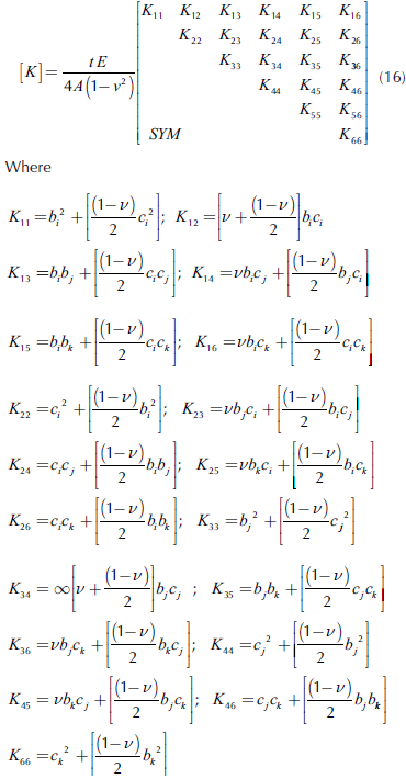
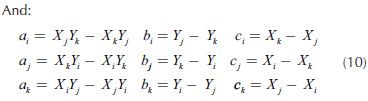
[K] is symmetric and bi, bi,, bk, ci, ci, and ck are definite by Equation (10). A is the area of the triangle. [K] is called the stiffness matrix.
In the Equation (14), {ƒ} is the force vector. If a Triangular. Linear Element (Figure 3) has surface stress on the side ij, pxand py, body force, bx and by(bulk unit weight), and concentrated load, P on node k., the resulting equation is:
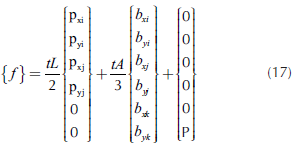
As the linear triangular element has six de gree of freedom, if there are concentrated loads, it goes in {ƒ} in the position of its degree of freedom. L is the length of each side of the element.
The Equation (14) is evaluated for each element of the grid. The global stiffness matrix and the global force vector {ƒ} come from element contributions. The [K] and {ƒ} of each element are introduced in [K] and {ƒ} global for all structural problem in function of each degree of freedom of each element.
To solve Equation (14), find {Un} and with Equations (13) and (1) find the stress σ.
For a plain concrete slab it has been demonstrated in texts on the mechanics of materials that the relationship between bending moment and stress is as follows:
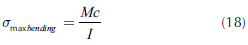
In the Equation (18), M (bending moment) = Mzz, and the moment of inertia regarding the neuter axis is l, and l = lzz. The direction of the axes is illustrated in Figure 2.
Proposed method to design (Camero Finite Element Method):
The following procedure is proposed:
- Calculate the bending moment considering that the vehicle is in the edge of the slab (See example).This is if the axle load from a moving vehicle will move along the floor or pavement and eventually crosses a joint. Other loadings, such as rack posts, swing lift trucks, or columns must be considered. PCA and WRI charts give thicknesses based on loadings at the interior of the floor slab (if the forklift's truck centre longitudinal axis, CC, coincide with the slab's centre longitudinal axis ¢).
-
From 1, the engineer obtains the maximum bending moment and with the results of finite element he obtains the maximum bending stress. He can also calculate the maximum bending stress applied to the slab (or pavement) with Equation (18).
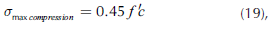
- Establish allowable stresses: the stresses should not exceed the elastic limit at any point. The following maximum compression and tension
- Calculate the thickness of the slab or pavement.
-
Verify that the applied stress calculated in Equation (21) is smaller than allowable, Equations (19) and (20). If it is not satisfactory, increase the slab thickness.
-
Verify that the reaction on the sub-grade is smaller than the bearing capacity of the same. Since soil cannot take tension stresses, the engineer must verify it (Bowles, 1975, pp. 504-514).
-
Verify slab shear stress resistance due to load action.
-
If the designer wants to design a structurally reinforced slab, select the load factor to give the design moment (greater than the applied moment). To this design moment, which is an ultimate moment, calculate the required steel areas and spacing. Use the theory of reinforcement concrete to calculate the required steel areas.
- Calculate the angular distortion. With finite element, for each node of the grid we have found the settlement. The results in Equation (14) gives us directly the settlement in each point of application of loading and helps us to calculate the angular distortion. For Flat floors a distortion angular limit = 1/1000 is recommended. Lambe and Whitman (1989, pp. 210-242) show an example.
Remember that the stress, σ, was obtained by finite element, and for each element with Equation (18) we calculate the bending moment.
is allowable concrete compression.
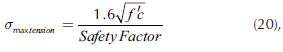
is allowable concrete tensile stress and the designer must specific passive steel as control for shrinkage and concrete temperature effects.
The typical way to calculate the thickness (t) of the slab or pavement is using a 1.0 meter-wide slab trip (or 1.0 foot-wide slab strip or 1.0 inch - wide slab trip). The Equation (18) takes the form:

Where b is the width of the transversal section of the slab or pavement being analyzed, taken as 1 meter (m.), 1 foot (12 inches) or 1 inch; and t is the slab or pavement thickness (Camero, 2007, and Ringo and Anderson, 1996).
In the following example, the slab adjacent and the mass of soil in the area of influence are considered. To determine this mass of soil, the attenuation of stress with its depth must be calculated. This can be done with Equation (14) and a big grid. The stress distribution can also be calculated following Perloff (1975) suggestion. The examples showed by Perloff (1975) indicate that the use of an equivalent circular area is an excellent approximation. Perloff (1975) shows it at the centerline: the stress due to the loaded area is maximum immediately below the loaded area, and attenuates to less than 10 percent of the initial vertical stress at a depth equal to twice the width of the loaded area or effective diameter of contact area.
Example to calculate bending moments
Example 1: Calculate the bending moment for designing an industrial floor with the following values:
Characteristics of the materials, site:
Concrete:
Concrete modulus of elasticity: Ec = 21 000 MPa
(3000 kpsi = 21 x 106 kN/m2)
Modulus of rupture: MR = 4.2 MPa (600 psi).
Concrete Poisson's ratio, v = 0.24 (See Mindess, young and Darwin, 2003).
Concrete, bulk unit weight: 24 kN/m3 (149.8 lb/ft3)
Soil:
Subgrade soil modulus of elasticity, E
Soil: = 25 100 kN/ m2 (3570 psi)
Soil, bulk unit weight: 18 kN/m3 (112.4 lb/ft3)
Soil Poisson's ratio, ν = 0.50
Safety Factor: 2.0
Slab width: 3.66 m = 12 ft.
Depth of analysis to consider (area of influence):
0.9 m = 2.95 ft.
Wide of analysis of slab adjacent:
Consider 0.90 m = 2.95 ft.
Forklift truck specifications:
Total axle load: 13 000 kg (28.6 kips = 127.4 kN), with equal wheel axle kpsi, then in Figure 2, P1 = P2 = 6500 kg (14.3 Kips = 63.7 kN for calculates, I have taken 65 kN).
Post Load in Slab Adjacent: 70.0 kN = 15.75 kpsi. Wheel Spacing (WS): 1.83 m (72 in). Tire Pressure: 65 kg/cm2 (930 psi). The wheel tread is a very hard material.
When the tire pressure is low (example: 5.6 kg/ cm2 = 80 psi), building the grid of finite element including the tire is recommended.
Slab width where the forklift truck goes was determinate by (Figures 2):
A = 1.76 m (69.29 in)
B = 0.07 m (2.76 in)
C = 3.59 m (141.34 in)
L = 3.66 m (144.09 in)
In Figure 4:
Wide joint: 0.01 m (0.39 in)
In Slab adjacent: A = 0.05 m (1.97 in) In this point there is a post load.
Slab thickness: 0.193 m = 7.6 in.
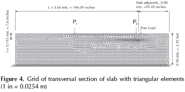
We will lay a grid as shown on Figure 4 and 5 with triangular elements on slab (transversal section). The boundary conditions can be seen: the line of soil where vertical displacements are zero (vi, vj, vk = 0 in the Equation (8) on the bottom line, Figure 4 -//////).
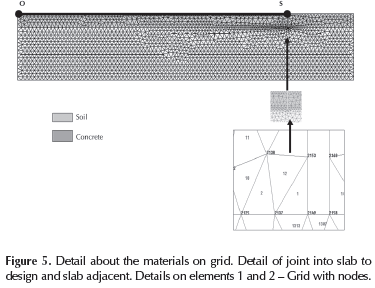
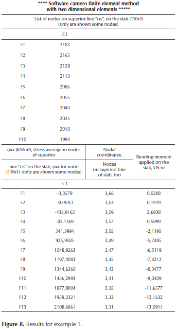
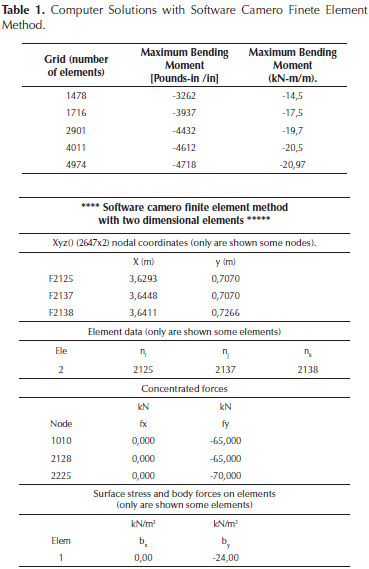
The Grid has 4974 elements and 2647 nodes.
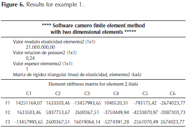
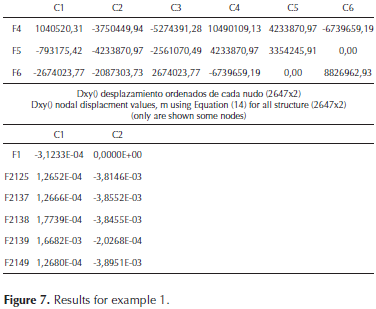
To solve the Equation (14) we have created a software. This software was created taking as a guide the software PEFICA (Linero, 2010). Examples of computer output are shown in Figures 6, 7 and 8.
The following moments were found by calculating the bending moment applied according to PCA and WRI methodologies (their design charts are given in Ringo and Anderson, 1996 and ACI 360, 2010. These documents present information on the design of slabs on grade with methods attributed to the PCA and WRI and examples that appear in the appendix. The design chart of PCA is shown in Gunalan, 1986, as well):


The following is obtained if the applied bending moment is calculated according to Camero Finite Element Method (Figure 4, 5, 6, 7 and 8):
For this example it was found that the real bending moment applied to the slab was 65 % greater than the one calculated by the PCA and/or WRI methods.
Figure 9. Illustrates the bending moment applied on the slab calculated with Camero Finite Element Method (on line "OS" in Figure 5).
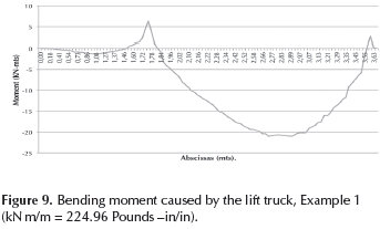
More accurate values for bending moment are obtained using grids with a larger number of linear triangular elements to obtain the converging value. The maximum bending moments for the various grids are summarized in Table 1. If we are interested in quantities, then we need a fine grid of linear triangular elements or other types like several quadratic elements.
Results discussion
If the maximum stresses applied to the slab were calculated with PCA and WRI methods, the thickness of slab (applying Equation (21)) would be t = 7.6 in (19.3 cm.), M = 2900 lb-in/in (12.9 kN-m/m) and safety factor of 2.0, and with Equation (18):

If the stress applied to the slab (pavement) is calculated according to the applied bending moment found with CAMERO Finite Element Method, the thickness of the plain concrete slab (with safety factor of 2.0, and with Equation 21), should be, t = 9.71 in (24.7 cm).
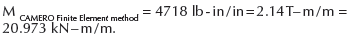
It can be found that with t = 7.6 in (19.3 cm) and M = 4718 lb-in/in (20.97 kN-m/m):
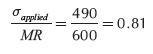
σmaximum applied tensiles scress = 490 psi (lb/in2) = 3.4 MPa. = 34.5 kg/cm2(This value is obtained with the software; see Figure 9).
If the σapplied/MR relationship is calculated, then the following is found:
Plain concrete slabs will generally sustain an infinite number of load repetitions (infinite amount of forklift truck traffic), as long as extreme fiber stress does not exceed 50 % of static modulus of rupture (see Camero, 2007, pp. 93-100 and Yoder and Witczak, 1975, p. 603).
Minor's charts (published in Yoder et al., 1975, p. 566, 603) show that there are 90 allowable repetitions of loaded axles of 13000 kg (127.4 kN), when σapplied/MR = 0.81. PCA and WRI safety factor for this example is 1.2 and not 2.0 as we believed according to PCA and WRI design charts. MA Minor found that if a load produces bending stress greater than half concrete rupture modulus, then such load induces material fatigue.
With the bending moment found with Camero Finite Element Method and safety factor of 2.0 we must select the Slab thickness. A plain concrete slabs design with Camero Finite Element Method will generally sustain an infinite number of load repetitions (infinite amount of forklift truck traffic), because the extreme fiber stress does not exceed 50 % of static modulus of rupture (Yoder et al., 1975,p. 602). In structural terms, the slab designed or pavement designed with Camero Finite Element Method has a lifelong useful life. The durability of concrete is very important too. If properly designed for the environment to which it will be exposed, and if carefully produced with good quality control, concrete is capable of maintenance free performance for decades without the need of protective coatings. The engineer can find an example of this in Mindess et al., 2003.
Conclusion
A new method to design slabs on grade for industrial floors is presented in this paper. The Camero Finite Element Method is the new solution to design slabs on grade and pavements.
The Camero Finite Element Method shows that the bending moment applied by the forklift truck on the slab is bigger than those considered by the simplified PCA and WRI design methods. This article explains how the traditional way of designing industrial floors critically reduces the lifespan of the floor.
Industrial floor design using the Camero Finite Element Method can sustain an infinite amount of traffic; while floors designed by traditional methods will only sustain a limited amount of traffic (limited number of load repetitions).
Industrial floors using the PCA and WRI methods can only support a smaller amount of traffic due to concrete fatigue. Even though 2.0 was used as a safety factor (calculated in relation to the modulus of rupture), this happens when the forklift truck's centroid loaded axle is eccentric with the slab's centroid. When the preceding occurs, the bending moment applied by the forklift truck loads is greater than that proposed by the PCA and WRI methods. The designed slabs (with PCA and WRI methods) allow a smaller amount of load repetitions to fail by fatigue. Ringo and Anderson, 1996, p. 29 quote: "PCA charts give thicknesses based on loading at the interior of the floor slab. The same is true for WRI charts". In other words, if the axle load from a moving vehicle travels along the floor and eventually cross a joint, the CAMERO FINITE ELEMENT METHOD is the best and recommended method to be used.
References
ACI Committee 360R/10. (2010). Guide to design of slabs-on-ground. American Concrete Institute. Farminton Hills, MI, USA. [ Links ]
Bowles J. (1975). Combined and special footings. Foundation Engineering Handbook. New York: Winterkorn and Fand. Van Nostrand Reinhold Company, 504-514. [ Links ]
Camero, H.E. (2007). A new method for designing floor slabs on grade due to the difficulty of applying simplified design methods, amongst them being the Portland Cement Association (PCA) and Wire Reinforcement Institute (WRI) methods. Journal INGENIERIA E INVESTIGACION, 27 (1), 93-100. [ Links ]
Gunalan, K.N. (1986). Analysis of industrial floor slab on ground for design purposes. Texas: Ph Disertation. [ Links ]
Lambe, T.W. & Whitman, R. (1989). Mecánica de Suelos. México: Editorial Limusa, pp. 215 - 242. [ Links ]
Linero, D., Garzón, D. & Ramírez, A. (2013). Introducción al análisis lineal de estructuras mediante el método de los elementos finitos, Vol. 1. Bogotá: Universidad Nacional de Colombia (en revisión). [ Links ]
Linero, D. & Garzón, D. (2010). Elementos de la mecánica del medio continúo para cuerpos sólidos, vol. 1. Bogotá: Universidad Nacional de Colombia. [ Links ]
Linero, D. (2010). Programa de elementos finitos a código abierto, PEFICA, vol. 1 y 2. Bogotá: Universidad Nacional de Colombia. [ Links ]
Mindess, S., Young, J.F. & Darwin, D. (2003). Concrete. New Jersey: Prentice Hall, 303-399, 476-545. [ Links ]
Oñate, E., (1995). Cálculo de estructuras por el método de elementos finitos. Barcelona: Centro Internacional de Métodos Numéricos en Ingeniería. [ Links ]
Perloff, W.H. (1975). Pressure Distribution and Settlement. Foundation Engineering Handbook. New York: Winterkorn Hans F. and Fang Hsay-Yang. Van Nostrand Reinhold Company, pp. 148-196. [ Links ]
Ringo, B.C. & Anderson, R. B. (1996). Designing Floor Slabs On Grade. Addison, Illinois: The Aberdeen Group, 25-41. [ Links ]
Segerlind, L.J. (1984). Applied finite element analysis. New York: John Wiley and Sons. [ Links ]
Timoshenko, S.P. and Goodier J.N. (1970). Theory of elasticity. Singapore: McGraw Hill Book Company. [ Links ]
Yoder, E.J. & Witczak, M.W. (1975). Principles of pavement design. New York: John Wiley and Sons, 559-624. DOI: 10.1002/9780470172919. [ Links ]
