


Services on Demand
Journal
Article
 English (pdf)
 Article in xml format
 Article references
 Send this article by e-mail
Indicators
-
 Cited by SciELO
 -
 Access statistics
Related links
-
 Cited by Google
 -
 Similars in
SciELO
Similars in
SciELO -
 Similars in Google
Share

 Permalink
Ingeniería e Investigación
Print version ISSN 0120-5609
Ing. Investig. vol.35 no.3 Bogotá Sept./Dec. 2015
https://doi.org/10.15446/ing.investig.v35n3.49623
DOI: http://dx.doi.org/10.15446/ing.investig.v35n3.49623.
Influence of moist air in copper heat sinks: Analysis through the entropy generation minimization criterion
La influencia del aire húmedo en disipadores de calor de cobre: Análisis a través del criterio de mínima generación de entropía
J. Cruz1, I. Amaya2, and R. Correa3
1 Jorge Cruz: Electronic Engineer, M.Sc. Escuela de Ingenierías Eléctrica, Electrónica, y de Telecomunicaciones, Universidad Industrial de Santander. Affiliation: Ph.D. student, Facultad de Ingeniería Mecánica, Eléctrica y Electrónica, Universidad de Guanajuato Campus Irapuato-Salamanca, México.
E-mail: jorge.cruz@ugto.mx.
2 Ivan Amaya: Mechatronic Engineer, Ph.D. Affiliation: Ph.D. student, Escuela de Ingenierías Eléctrica, Electrónica y de Telecomunicaciones, Universidad Industrial de Santander, Colombia.
E-mail: ivan.amaya2@correo.uis.edu.co.
3 Rodrigo Correa: Chemical Engineer, Ph.D. Affiliation: Professor, Escuela de Ingenierías Eléctrica, Electrónica y de Telecomunicaciones, Universidad Industrial de Santander, Colombia.
E-mail: crcorrea@uis.edu.co.
How to cite: Cruz, J., Amaya, I., & Correa, R. (2015). Influence of moist air in copper heat sinks: Analysis through the entropy generation minimization criterion. Ingeniería e Investigación, 35(3), 44-52. DOI: http://dx.doi.org/10.15446/ing.investig.v35n3.49623.
ABSTRACT
Many factors affect heat transfer during the cooling of modern electronic devices. Today, knowledge accrues from modeling, simulation, and experimentation. This allows predicting and calculating features of heat transfer phenomena, to some extent. Examples include the amount of heat generated and removed, the required physical properties of the working fluid, and the required material properties of the heat sink, among other parameters. This article describes some simulation results of using air with a given relative humidity (10 %, 50 % and 90 %). Its influence on the heat transfer process was also analyzed. Results show a measurable effect of using humidified air instead of dry air and copper as a bulk material. The heat transfer rate increased about 20 % when using air with 90 % relative humidity passing through a rectangular microchannel heat sink made of copper.
Keywords: Heat sinks, microelectronics, global optimization, entropy generation minimization, moist air.
RESUMEN
Son muchos los factores que afectan la transferencia de calor durante el enfriamiento de los dispositivos electrónicos modernos. En la actualidad, el conocimiento acumulado proviene del modelado, la simulación, y la experimentación. Esto permite predecir y calcular características de fenómenos de transferencia de calor, hasta cierto punto. Ejemplos de ello incluyen la cantidad de calor generado y removido, las propiedades físicas necesarias para un fluido de trabajo, y las propiedades requeridas para el material de un disipador de calor, entre otros parámetros. Este artículo describe algunos resultados de simulación utilizando aire con un valor de humedad relativa dado (10, 50 y 90 %). Su influencia en el proceso de transferencia de calor también fue analizado. Los resultados muestran un efecto medible del uso de aire humedecido en lugar del aire seco y del cobre como material del disipador. La tasa de transferencia de calor incrementó alrededor de 20 %, utilizando aire con 90 % de humedad relativa que atraviesa un disipador de calor de microcanales rectangulares hecho de cobre.
Palabras clave: Disipadores de calor, microelectrónica, optimización global, mínima generación de entropía, aire húmedo.
Received: March 13th 2015 Accepted: July 13th 2015
Introduction
Use of heat sinks with optimal thermal efficiency is paramount to preserve the integrity of electronic devices. Hence, it is a well-defined research topic nowadays. Electronic equipment operating at high clock rates requires performance levels that liberate large amounts of energy as heat. Different approaches based on modeling, simulation, and experimentation have led to several proposals, such as changes in geometry, bulk material, and working fluid, as well as their physicochemical properties. Nowadays, microchannel heat sinks of rectangular cross section are widely used due to their simplicity, ease of manufacture, and high thermal energy dissipation efficiency. However, their performance must still be improved through systematic modifications. In this sense, Tuckerman & Pease (1981) studied the effectiveness of using liquid water as the working fluid for silicon heat sinks, considering power densities of about 790 W/cm2. Kleiner et al. (1995) increased the thermal efficiency of heat sinks by injecting pressurized air. Furthermore, several authors report their simulation and experimental results using working fluids such as nitrogen, helium, argon, carbon dioxide, and ammonia gas (Adham et al. 2013). Recent results deal with some technical alternatives, still under development, such as nanofluids, magnetic fluids, two-phase fluid flow, and flow boiling, among others (Adham et al. 2013, Hatami & Ganji 2014, Yang et al. 2014). Likewise, some studies have tested different kinds of materials with excellent thermal properties, which could be used for manufacturing heat sinks. Yin et al. (2013) deposited aluminum nitride (AlN) on a rectangular microchannel heat sink, reaching an 80 % decrease of thermal resistance when compared to traditional structures. Bower et al. (2003) experimented with water as a cooling fluid and a microchannel made of SiC; their results improved upon those of a copper heat sink with air. Turkakar (2010) noted that heat flows of about 150 W/cm2 can be removed by a metal-polymer heat sink, and that pressure drop of the working fluid can be reduced by widening the channels. In a similar fashion, reports exist regarding the use of different bulk materials, such as aluminum and copper (Huang & Leu 2015, Solmuş 2015).
An analogy between electric current and heat transfer is a widespread modeling technique. In this sense, efforts have been carried out to minimize the equivalent thermal resistance (Hatami & Ganji 2014, Kuppusamy et al. 2014). Moreover, heat transfer and hydrodynamic phenomena are present. The former is due to conduction, convection, and/ or radiation. The latter is owed to the flow of the working fluid. So, an interaction between them is natural when cooling an electronic device with a heat sink. On one hand, the film coefficients, the thermal conductivity and/or the thermal emissivity, appear. On the other, pressure drop between the inlet and the outlet of the microchannel, and the thermodynamic properties of the working fluid, exist. It is worth noting that during this study the effect of heat transfer as a result of thermal radiation has been disregarded. This decision was made to keep the resulting mathematical model as simple as possible, among other things.
The working fluid stimulates heat transfer due to convection, but is affected by the pressure drop between the channel's inlet and outlet. Hence, researchers have weighed the trade-off between thermal resistance and pressure drop (inversely related by nature) through multi-objective design strategies, striving to reach optimum designs and operating conditions. As an example, Karathanassis et al. (2013) used Pareto fronts for finding an optimum design of a microchannel for a thermal system. They simultaneously improved the thermal and hydrodynamic efficiencies. In the same way, Adham et al. (2012) boosted the performance of a heat sink by reducing the entropy generation rate 34 %, whilst also optimizing the pumping power. They managed to do so by using ammonia gas as a working fluid, instead of air.
It is evident that developments in this area aim at finding optimum values for the heat sink and for the operating conditions. For example, one may desire to maximize the efficiency of energy dissipation, or the area for energy dissipation. Likewise, minimizing the weight, the cost, or the power consumption of pumping the working fluid may be desired. Bejan (1995) proposed an alternative for such an endeavor (although it is not the only one), based on minimizing the entropy generated by a system. As expected, this Entropy Generation Minimization (EGM) has its roots on the second law of thermodynamics. EGM associates phenomena related to heat and mass transfer in its most elemental model. This approach is based on entropy balances, and strives to reduce the influence of the irreversibility present in a thermodynamic system. Culham & Muzychka (2001) implemented this approach when they designed optimum plate-fin heat sinks and microchannel heat sinks.
Almost concurrently, researchers studied different optimization approaches, based on heuristics, to solve complex problems that cannot be easily tackled through classic algorithms (Adham et al. 2014, Correa et al. 2011, Hinojosa et al. 2012, Khan et al. 2013). Simulated Annealing (SA) was one of the pioneers in this field. SA is based on an analogy to the controlled cooling of a given metal. Afterwards, several proposals appeared, but most of them are simple analogs of biological processes, of swarm behavior (e.g. animals), and of teaching processes, just to name a few. The number of publications regarding the use of this kind of approaches in engineering is breathtaking, especially since traditional ones are unable to solve them. In the particular case of optimum design of heat sinks, a brief list is composed by Adham et al. 2012 and 2014, Correa et al. 2011, Hinojosa et al. 2012, and Khan et al. 2013.
This article presents an analysis of the influence of air humidity over the entropy generation of a rectangular microchannel heat sink. The model of the system was developed through the EGM criterion; and was optimized using the Spiral Optimization algorithm, because it is simple, reliable, and easy to tune. We begin by showing a brief description of the mathematical method and of the optimization algorithm before moving on to the methodology. Afterwards, the resulting data is discussed and at the end conclusions are drawn out.
Fundamentals
Mathematical model
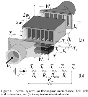
Figure 1 shows an overview of the system under analysis. It comprises a rectangular microchannel heat sink and a thermal paste between the heat sink and the chip. The heat sink is an array of NC =((Wd/2 - wp)/(wc+w )) channels with a geometry defined by: the width 2wc, the height Hc, and the length of the channel Ld, as well as the width of the fins (or walls) 2wp. The total volume of the heat sink is given by Wd x Hd x Ld, where Wd represents its width, Hd its height, and Ld its length. Also, the model considers the thickness of the heat sink's base and of the thermal interface, t, and t. respectively. The effective area for heat transfer of the thermal paste is given by W.x L.. This figure also includes the equivalent thermal system detailing the nomenclature used for temperatures.
After defining the geometry of the system, the operating conditions can be established. They are (Khan et al. 2006; Lee et al. 1995; Shao et al. 2011):
Conditions regarding material and geometry:
- The material of the heat sink is isotropic (macroscopically) and a good thermal conductor; the chip-heat sink interface is a thermal paste that reduces finite temperature difference due to contact; the heat transfer area of the chip is the same as that of the thermal paste; the area of the heat sink's base is bigger than the heat transfer area of the chip; roughness in the inner surfaces of the channels is disregarded; the hydraulic diameter (Dh) is quite higher than the mean free path (A) of the working fluid (Dh > 1000 A).
Conditions regarding heat transfer:
- The heat flux generated by the electronic device is steady, and enters the heat sink through the bottom plate; thermal dispersion/contraction effect is considered since heat travels from one body to another with different area; all of the heat generated by the chip is transferred to the working fluid by the heat sink, via convection; heat transfer to the upper plate is disregarded since it is at room temperature; changes in the kinetic and potential energies are negligible. As a first approximation, and for keeping the model as simple as possible, heat transfer by thermal radiation was not considered here.
Conditions regarding mass transfer:
- For the given operating conditions, thermophysical properties of the working fluid are approximately constant inside the heat sink; the flow of the working fluid is steady, and can be considered to be hydrodynamically completely developed. This flow can be either laminar or turbulent. Transition regime is disregarded.
Entropy generation rate
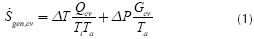
Based on symmetry conditions, the control volume for our study can be defined as half a channel, with a size of (wc + w) x (Hc + tb +1) xLd. Using the second relation of Gibbs, and balances of mass, energy, and entropy, one arrives at the entropy generation rate of the control volume ( gen,cv), given by Equation (1).This equation relates gen,cvwith the temperature of the interface (Ti) and of the environment (Ta), as well as with the temperature difference (ΔT= Ti- Ta ), the heat flow
 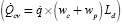 , the pressure drop (ΔP) and the volumetric flow (Gcv ).
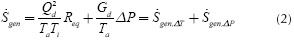
Hence, it is straightforward to find an expression that describes the entropy generation rate (gen) for the whole heat sink, as shown in Equation (2). The first part represents a measure of the irreversibility due to heat transfer, and it depends on the total heat transfer  , on temperatures T and Ta, and on the equivalent thermal resistance (Req= ΔT/QJ. The second part represents the irreversibility due to mass flow transfer, and depends on total volumetric flow that goes through the channels (Gd, on total pressure drop (ΔP)and on temperature Ta.
Next, each component of the mathematical model is described, in order to further the details and to improve the physical description of the problem.
Equivalent thermal resistance
In order to find the equivalent thermal resistance of the whole heat sink, Req, each component must be described as a function of the heat transfer mechanisms present between the thermal paste and the environment, as shown in Equation (3),
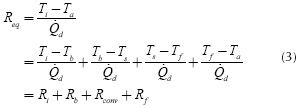
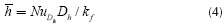
where R i, Rb, Rcov and R f are the thermal resistances of v o' conv f the interface, the heat sink base, the heat transfer due to convection in the channels, and of the calorific capacity of the working fluid, respectively. Ti, Tb, Ts , Tf and Ta are the average temperatures of the interface, the heat sink base, the internal wall of the channels, the fluid, and of the environment, respectively (see Figure 1). Because of space restrictions, a detailed description of each resistance is omitted. One important parameter in this process is the film coefficient, or convection heat transfer coefficient ( ), which depends on several experimental parameters. Moreover, this coefficient relates to the Nusselt number ( NuDh) to the thermal conductivity of the fluid (kf), and to the effective hydraulic diameter of the channel (Dh = 4wcHc/(2wc+Hc)), as shown in (4),
To calculate , the following empirical correlations were used (Incropera & DeWitt 1996, Kim & Kim 1999, Kleiner et al. 1995),
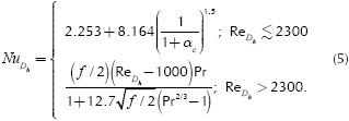
HereReDh is the Reynolds number for the hydraulic diameter Dh f the friction factor, αc, A, B, Ld are geometrical factors, and αc= 2wc /Hc is defined as the channel aspect ratio.
This study assumes that the film coefficient depends only on the material, on the fluid, and on the operating conditions of the internal surfaces. Furthermore, the air-water mixture is assumed to behave ideally, with water vapor as a dilute component. The dew points were calculated via the Magnus formula and the Arden-Buck equation. For the present case, the results show that the mixtures were above their saturation point. Thomas et al. recently proposed an empirical correlation dealing with the convective heat transfer coefficient for an air-water mixture as a function of relative humidity (RH), and the surface-to-ambient temperature difference ΔT (Thomas et al. 2012). In this case, the surface material was oxygen free copper. They found a clear dependence of that coefficient with humidity levels. This correlation was implemented as a second approximation, and for comparison purposes. It is given by

The equivalent thermal resistance of the whole heat sink, defined in Equation (3), was rewritten in Equation (8) as,
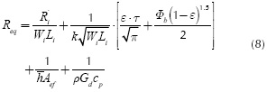
where R'i is the contact thermal resistance times unit area (m2 x K/W) and k is the thermal conductivity of the solid; e and t are dimensionless values of the equivalent radius of the heat source and of the base plate thickness. Φb is an adimensional parameter of the model. Aef is the effective area to convective heat transfer, p is the average density of the fluid and cp is the specific heat of the fluid that goes throughout the microchannels of the heat sink. Some parameters of Equation (8) are not completely detailed due to space restrictions. Nonetheless, more information about them is found in Cruz et al. 2015.
Total pressure drop
In order to determine the total pressure drop (ΔP), one must account for the drop through the channels of the heat sink (ΔPd), as well as for the drop through the supply tubes (ΔPtu). Using additional empirical correlations reported in literature (Kleiner et al. 1995), the final expression is given by
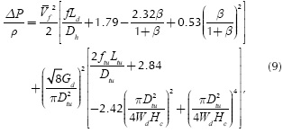
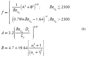
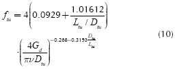
where β(= wc/wc ) is the channel-wall ratio, Ltu and Dtu are length and inner diameter of the supply tubes of fluid flow, and, v is the kinematic viscosity of the fluid. The friction factors f and ftu are related to the inner part of the microchannels and to the supply tubes, respectively. According to Kleiner et al. (1995), the former is calculated through Equation (6) and the latter through Equation (10),
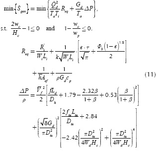
The objective function
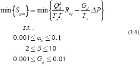
Equation (11) summarizes the objective function used in this study for designing a microchannel heat sink, considering the previously described components, i.e. (3)-(9). The aforementioned operating conditions and the design constraints are also included in Equation (11), as The equivalent thermal resistance of the whole heat sink, well as the expressions for Req and ΔP, which are rewritten for the sake of clarity and ease of reading.
Spiral optimization
Tamura & Yasuda (2011) presented a strategy based on the geometric spiral (SO). This method emulates the dynamics of a set of points that revolve around a reference point (or origin point) following the path of a logarithmic spiral. At each iteration, the reference point changes to the best position according to the objective function. SO focuses on the search strategies of diversification and intensification. The first one, also known as exploration, identifies a portion of the search domain where the algorithm is likely to find the best solution. The second one is a detailed search (or exploitation) within the region identified by the previous strategy. All this happens just by using the general equation of SO, shown in Equation (12), that updates the position of each point with respect to the reference point,
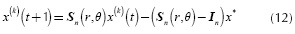
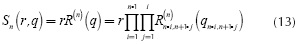
where x(k)(t) is the position x of the k-th point at time step t, and each position is represented in the n-dimensional search domain as x = [x1x2,...xn ]T with a total number of search pointsΨso for k= 1,2,...Ψso . In is the identity matrix for n dimensions and x*is the origin point (and also, the current best solution). The stable matrix Sn is the scalar product between the rotation matrix R(n),(θ) with r, as shown by Equation (13), where r and θ are the convergence rate between a point and the origin, and the rotation angle around the origin, respectively. These two are defined for the intervals 0 < r < 1 and 0 ≤ θ ≤ 2Π. The rotation matrix R(n)(θ) in Equation (13), is the product of all possible combinations of the rotation matrices R(n)i,j(θi,j ), per each xi-xj plane in the search domain.
Methodology
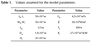
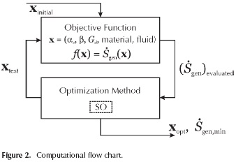
Throughout this work, simulation results were obtained using an ASUS® S46C laptop with: Intel® CoreTM i7-3537U CPU @ 2.00 GHz - 2.50 GHz, 6 GB RAM, Microsoft® WindowsTM 8.1 Single - 64 bits. The Spiral Optimization (SO) algorithm was used to solve the problem shown in Equation (11), and rewritten in Equation (14), along with the design specification laid out in Table 1. Figure 2 describes the order of the computational procedure, as well as the connection between the spiral optimization technique and the mathematical model (also named here as the cost function). Striving to find the best set of parameters for SO, tests with 17 standard test functions were run, finding a higher convergence rate whenever ΨSO= 100, r=0,99 and θ = Π/8. These functions were chosen because they behave similarly to the objective function, but the data is not shown due to space restrictions. In all cases, each experiment was repeated 50 times and a maximum of 1000 iterations was defined.
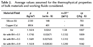
The first part of our study considered silicon (Si) and copper (Cu) as feasible bulk materials, and dry air as working fluid. The volumetric flow rate (Gd) was selected as a design specification. During the second part, air was still used as a working fluid but three values of relative humidity (RH) were considered, i.e. 0.1, 0.5, and 0.9. In order to incorporate this phenomenon, the thermophysical properties of the materials and fluids shown in Table 2 were used. In the case of moist air, the properties were calculated using software 6 (toolbox 13) from Morvay & Gvozdenac (2008). We also calculated the average film coefficient () through two approaches, where the first one is described by Equation (4), and the second one by Equation (7).
Results and discussion
Comparison between Si and Cu when using dry air as a working fluid
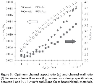
Figure 3 presents the optimum aspect ratios of the channel (αc) and of the channel-wall (β) for different volumetric flow rates (Gd). In this figure, each marker relates to a specific design scenario. There is a clear increasing behavior for both αc and β, and their tendency implies that in order to reduce the losses associated to heat and mass transfer, wider channels and thinner walls are required. Figure 3 also implies there is a difference in the optimum aspect ratios of silicon and copper heat sinks, becoming steeper for Gd>0,005 m3/s. Thus, Cu heat sinks exhibit ∼5% wider channels when compared to heat sinks made of Si. This favors the minimum entropy generation rate (gen,min ) significantly, reaching values about 21 % lower (Figure 4). This is mainly due to the lowered thermal properties of silicon, when compared to copper.
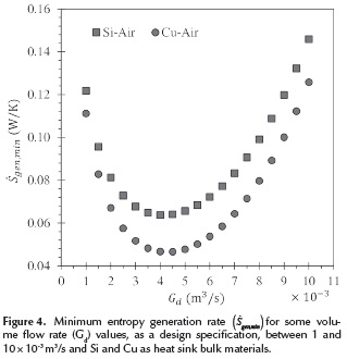
Should Gd also be regarded as a design variable, Figure 4 shows that in order to reach the minimum entropy generation (gen,min ) for any of the two bulk materials, the volumetric flow rate must comply with 0,004 < Gd <0,0045 m3/s.
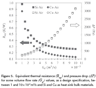
Figure 5 shows the equivalent thermal resistance (Req) and the pressure drop (ΔP) as a function of Gd for each one of the previously commented design scenarios. The former, i.e. Req, diminishes as Gd increases, whilst the opposite happens with the latter (i.e. ΔP increases for higher Gd).This behavior relates to the previous analysis of αc and β in the following way: a higher volumetric flow rate (GJ requires wider channels, which in turn increases the effective area for heat transfer, reducing the thermal resistance. But this increase also requires a higher pumping power to maintain the flow supply, thus increasing the pressure drop (ΔP). Hence, an appropriate setting of Req and ΔP provides the minimum entropy generation rate (gen,min ), which becomes evident if one focuses on the intersection of the curves of each component (i.e. Rq and ΔP) for both materials (Figure 5). This intersection corresponds to the global minima shown in Figure 4.
As a complimentary analysis, the total mass of optimum heat sinks was calculated for different values of (Gd).It was also found that increasing the volumetric flow rate lowers the material requirement. Moreover, optimum Cu heat sinks have about 72 % more mass than those made of Si. In other words, copper heat sinks are heavier than those made of silicon, so their applicability on situations with weight restrictions is limited.
Effect of moisture level on Cu heat sinks
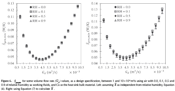
Figure 6 shows the minimum entropy generation rate (gen,min ) for optimum copper heat sinks and different volumetric flow rates (Gd). Air with different values of relative humidity (i.e. moisture levels) are considered as working fluids (i.e., 0.0, 0.1, 0.5 and 0.9). When compared against the data yielded for dry air, it was observed that the efficiency of copper heat sinks improves slightly as moisture increases, reaching a reduction in gen,min of 0.42 %, 1.27 % and 2.11% for 0.1, 0.5 and 0.9 of relative humidity, respectively.. Allowing to become a design variable yields that the best value of gen,min is achieved whenever Gd = 0,0045 m3/s.
Entropy generation for Cu heat sinks using moist air
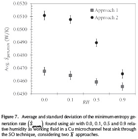
Figure 7 shows the average gen,minvalues for copper heat sinks, considering two approaches for calculating the film coefficient () at different moisture levels. The first approach assumes that the film coefficient only depends on the material. The second one assumes that it only depends on the relative humidity. The error bars in Figure 7 are the standard deviation of gen,min for each design scenario. It is worth remembering that during these tests, αc, β and Gd were treated as design variables. As mentioned in the previous section, increasing the relative humidity of air improves the entropy generation rate for copper heat sinks. The designs yielded through the first approach are about 6 % more efficient than those of the second approach. Still, both of them are adequate for designing microchannel heat sinks with moist air as working fluid (although the second one was experimentally obtained, so its results represent a better real approximation). However, controlling the humidity level of air requires the use of specialized equipment, and this implies an additional energetic and economic cost. Nonetheless, an estimate humidity level of the environmental air can be included as a design specification, so an optimum design closer to real life operating conditions can be found.
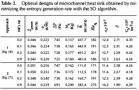
Finally, Table 3 complements the data presented in Figure 7 showing values of minimum entropy generation rate, equivalent thermal resistance, pressure drop, total mass, Reynolds number, Nusselt number, and of the design variables (αc,β and Gd). In all cases, we found that moist air was always in the laminar regime (i. e.ReDh <2300).
Conclusions
Throughout this work, we modeled two types of rectangular microchannels based on the Entropy Generation Minimization (EGM) criterion. They were optimized using the Spiral Optimization (SO) algorithm, and silicon and copper as bulk materials. The effect of moist air as a working fluid was analyzed. The lack of more realistic expressions valid for calculating , led to the adoption of two extreme approaches. We found that the minimum entropy generation rate (gen,min) decreases around 21 % when using Cu instead of Si. But the latter demands about 72 % less mass than the former. This must be taken into account when considering applications with weight restrictions. We also determined that increasing the humidity of air to 0.1, 0.5 and 0.9 decreases gen,min0.42 %, 1.27 % and 2.11 %, respectively. Hence, the efficiency of microchannel heat sinks (made of either Si or Cu) can be set by controlling the moisture of the air. Or, at the very least, moisture level of a given environment can be included into the design process to optimize a design closer to real life operating conditions. We deem as feasible the use of a rectangular microchannel made of copper with moist air as a working fluid, instead of one made of silicon with dry air.
Acknowledgement
The authors would like to express their gratitude to Vicerrectoría de Investigación y Extensión at Universidad Industrial de Santander (Colombia), for the support granted through project 1807.
References
Adham, A. M., Mohd-Ghazali, N., & Ahmad, R. (2012). Optimization of an ammonia-cooled rectangular microchannel heat sink using multi-objective non-dominated sorting genetic algorithm (NSGA2). Heat and Mass Transfer, 48(10), 1723-1733. DOI: 10.1007/s00231-012-1016-8. [ Links ]
Adham, A. M., Mohd-Ghazali, N., & Ahmad, R. (2013). Thermal and hydrodynamic analysis of microchannel heat sinks: A review. Renewable and Sustainable Energy Reviews, 21, 614-622. DOI: 10.1016/j.rser.2013.01.022. [ Links ]
Adham, A. M., Mohd-Ghazali, N., & Ahmad, R. (2014). Optimization of a Rectangular Microchannel Heat Sink Using Entropy Generation Minimization (EGM) and Genetic Algorithm (GA). Arabian Journal for Science and Engineering. DOI: 10.1007/s13369-014-1253-x. [ Links ]
Bejan, A. (1995). Entropy generation minimization: The new thermodynamics of finite-size devices and finite-time processes. Journal of Applied Physics (Vol. 79). New York: CRC press. [ Links ]
Bower, C., Ortega, A., Skandakumaran, P., Vaidyanathan, R., Green, C., & Phillips, T. (2003). Heat Transfer in Water-Cooled Silicon Carbide Milli-Channel Heat Sinks for High Power Electronic Applications. En 2003 ASME International Mechanical Engineering Congress & Exposition (Vol. 2003, p. 9). Washington, D.C., USA: ASME. DOI: 10.1115/IMECE2003-43374. [ Links ]
Correa, R., Amaya, I., & Araque, A. (2011). Uso de algoritmos metaheurísticos híbridos para la minimización de entropía en problemas de transferencia de calor en circuitos electrónicos. Revista Ingeniería y Universidad, 15(2), 403421. [ Links ]
Cruz, J., Amaya, I., & Correa, R. (2015). Optimal rectangular microchannel design, using simulated annealing, unified particle swarm and spiral algorithms, in the presence of spreading resistance. Applied Thermal Engineering, 84, 126-137. DOI: 10.1016/j.applthermaleng.2015.03.049. [ Links ]
Culham, J. R., & Muzychka, Y. S. (2001). Optimization of plate fin heat sinks using entropy generation minimization. IEEE Transactions on Components and Packaging Technologies, 24(2), 159-165. DOI: 10.1109/6144.926378. [ Links ]
Hatami, M., & Ganji, D. D. (2014). Thermal and flow analysis of microchannel heat sink (MCHS) cooled by Cu-water nanofluid using porous media approach and least square method. Energy Conversion and Management, 78, 347358. DOI: 10.1016/j.enconman.2013.10.063. [ Links ]
Hinojosa, A., Espinosa, K., & Correa, R. (2012). El método de enjambre de partículas y el criterio de mínima entropía en el diseño óptimo de un disipador de calor. Revista Ingenierías Universidad de Medellín, 11(20), 203-214. [ Links ]
Huang, D.-J., & Leu, T.-S. (2015). Condensation heat transfer enhancement by surface modification on a monolithic copper heat sink. Applied Thermal Engineering, 75, 908917. DOI: 10.1016/j.applthermaleng.2014.10.019. [ Links ]
Incropera, F. P., & DeWitt, D. P. (1996). Fundamentals of heat and mass transfer. John Wiley & Sons. [ Links ]
Karathanassis, I. K., Papanicolaou, E., Belessiotis, V., & Bergeles, G. C. (2013). Multi-objective design optimization of a micro heat sink for Concentrating Photovoltaic/Thermal (CPVT) systems using a genetic algorithm. Applied Thermal Engineering, 59(1-2), 733-744. DOI: 10.1016/j.applthermaleng.2012.06.034. [ Links ]
Khan, W. A., Kadri, M. B., & Ali, Q. (2013). Optimization of Microchannel Heat Sinks Using Genetic Algorithm. Heat Transfer Engineering, 34(4), 279-287. DOI: 10.1080/01457632.2013.694758. [ Links ]
Khan, W. A., Yovanovich, M. M., & Culham, J. R. (2006). Optimization of microchannel heat sinks using entropy generation minimization method. En Twenty-Second Annual IEEE Semiconductor Thermal Measurement And Management Symposium (pp. 78-86). Dallas, TX, USA: IEEE. DOI: 10.1109/STHERM.2006.1625210. [ Links ]
Kim, S. J., & Kim, D. (1999). Forced Convection in Microstructures for Electronic Equipment Cooling. Journal of Heat Transfer, 121(3), 639. DOI: 10.1 1 15/1.2826027. [ Links ]
Kleiner, M., Kühn, S., & Haberger, K. (1995). High performance forced air cooling scheme employing microchannel heat exchangers. IEEE Transactions on Components, packaging, and manufacturing technology-Part A, 18(4), 795-804. [ Links ]
Lee, S., Song, S., Au, V., & Moran, K. P. (1995). Constriction/ Spreading Resistance Model for Electronics Packaging. En Proceedings of the 4th ASME/JSME thermal engineering conference (Vol. 4, pp. 199-206). [ Links ]
Morvay, Z., & Gvozdenac, D. (2008). Applied Industrial Energy and Environmental Management. Wiley-IEEE Press. [ Links ]
Raja Kuppusamy, N., Saidur, R., Ghazali, N. N. N., & Mohammed, H. A. (2014). Numerical study of thermal enhancement in micro channel heat sink with secondary flow. International Journal of Heat and Mass Transfer, 78, 216-223. DOI: 10.1016/j.ijheatmasstransfer.2014.06.072. [ Links ]
Shao, B., Wang, L., Li, J., & Cheng, H. (2011). Multi-objective optimization design of a micro-channel heat sink using adaptive genetic algorithm. International Journal of Numerical Methods for Heat & Fluid Flow, 21(3), 353-364. DOI: 10.1108/09615531111108512. [ Links ]
Solmuş,  . (2015). Numerical investigation of heat transfer and fluid flow behaviors of a block type graphite foam heat sink inserted in a rectangular channel. Applied Thermal Engineering, 78, 605-615. DOI: 10.1016/j.applthermaleng.2014.11.066. [ Links ]
Tamura, K., & Yasuda, K. (2011). Spiral optimization -A new multipoint search method. En 2011 IEEE International Conference on Systems, Man, and Cybernetics (pp. 17591764). IEEE. DOI: 10.1109/ICSMC.201 1.6083926. [ Links ]
Thomas, A.V., Koratkar, N., & Peles, Y. (2012). Dehumidification heat transfer on copper surfaces. International Journal of Heat and Mass Transfer, 55(25-26), 7858-7864. DOI: 10.1016/j.ijheatmasstransfer.2012.08.019. [ Links ]
Tuckerman, D. B., & Pease, R. F. W. (1981). High-performance heat sinking for VLSI. IEEE Electron Device Letters, 2(5), 126-129. DOI: 10.1109/EDL.1981.25367. [ Links ]
Türkakar, G. (2010). Numerical Simulation and Analytical Optimization of Microchannel Heat Sinks (MSc. Thesis). Middle East Technical University. [ Links ]
Yang, Y.-T., Tsai, K.-T., Wang, Y.-H., & Lin, S.-H. (2014). Numerical study of microchannel heat sink performance using nanofluids. International Communications in Heat and Mass Transfer. DOI: 10.1016/j.icheatmasstransfer.2014.07.006. [ Links ]
Yin, S., Tseng, K. J., & Zhao, J. (2013). Design of AlN-based micro-channel heat sink in direct bond copper for power electronics packaging. Applied Thermal Engineering, 52(1), 120-129. DOI: 10.1016/j.applthermaleng.2012.11.014. [ Links ]
