


Servicios Personalizados
Revista
Articulo
 Inglés (pdf)
 Articulo en XML
 Referencias del artículo
 Enviar articulo por email
Indicadores
-
 Citado por SciELO
 -
 Accesos
Links relacionados
-
 Citado por Google
 -
 Similares en
SciELO
Similares en
SciELO -
 Similares en Google
Compartir

 Permalink
Ingeniería e Investigación
versión impresa ISSN 0120-5609
Ing. Investig. vol.35 no.3 Bogotá set./dic. 2015
https://doi.org/10.15446/ing.investig.v35n3.47543
DOI: http://dx.doi.org/10.15446/ing.investig.v35n3.47543.
Mechatronics methodology: 15 years of experience
Metodología mecatrónica: 15 años de experiencia
E. Gorrostieta1, E. Vargas-Soto2, L. Zuñiga-Aviles3, J. Rodriguez-Resendiz4, and S. Tovar-Arriaga5
1 Efrén Gorrostieta: Electronics Engineer, ITESO, Mexico. Ph.D. in Mechatronics Engineering, CIDESI, Mexico. Affiliation: Professor at the Autonomous University of Queretaro, Mexico.
E-mail: efrengorrostieta@gmail.com.
2 Emilio Vargas Soto: Mechanical Engineer, UNAM, Mexico. Ph.D. in Informatics and Automation, Complutense University of Madrid, Spain. Affiliation: Professor at the Autonomous University of Queretaro, Mexico.
E-mail: emilio@mecatronica.net.
3 Luis Adrián Zúñiga Avilés: Ph.D. in Mechatronics Engineering, CIDESI, Mexico.
E-mail: adriandgim@gmail.com.
4 Juvenal Rodriguez Resendiz: Automation Engineer, Doctor in Engineering, Affiliation: Professor at the Autonomous University of Queretaro.
E-mail: juvenal@uaq.edu.mx.
5 Saúl Tovar Arriaga: Electrical Engineer, Queretaro Institute of Technology, Mexico. M.Sc. in Mechatronics, University of Siegen, Germany, Doctor in Biomedical Engineering, University of Erlangen-Nuremberg, Germany.
E-mail: saulotov@yahoo.com.mx.
How to cite: Gorrostieta, E., Vargas-Soto, E., Zuñiga-Aviles, L., Rodri-guez-Resendiz, J., & Tovar-Arriaga, S. (2015). Mechatronics methodology: 15 years of experience. Ingeniería e Investigación, 35(3), 107-114. DOI: http://dx.doi.org/10.15446/ing.investig.v35n3.47543.
ABSTRACT
This article presents a methodology to teach students to develop mechatronic projects. It was taught in higher education schools, in different universities in Mexico, in courses such as: Robotics, Control Systems, Mechatronic Systems, Artificial Intelligence, etc. The intention of this methodology is not only to achieve the integration of different subjects but also to accomplish synergy between them so that the final result may be the best possible in quality, time and robustness. Since its introduction into the educational area, this methodology was evaluated and modified for approximately five years, were substantial characteristics were adopted. For the next ten years, only minor alterations were carried out. Fifteen years of experience have proven that the methodology is useful not only for training but also for real projects. In this article, we first explain the methodology and its main characteristics, as well as a brief history of its teaching in different educational programs. Then, we present two cases were the methodology was successfully applied. The first project consisted in the design, construction and evaluation of a mobile robotic manipulator which aims to be used as an explosives ordnance device. In the second case, we document the results of a project assignment for robotics tasks carried out by students which were formerly taught with the methodology.
Keywords: Methodology, mechatronic, education, robotics.
RESUMEN
En este artículo se presenta una metodología para enseñar a los estudiantes a desarrollar proyectos mecatrónicos. Se implementó en las escuelas de educación superior, en diferentes universidades, en México en cursos tales como: Robótica, Sistemas de Control, Sistemas mecatrónicos, Inteligencia Artificial, etc. La intención de esta metodología no es solo lograr la integración de las diferentes asignaturas, sino también realizar una sinergia entre ellas para así obtener un mejor resultado en términos de calidad, tiempo y robustez. Desde su introducción en el ámbito educativo, esta metodología ha sido evaluada y modificada por aproximadamente cinco años, adoptando características sustanciales. Durante los siguientes diez años, sólo se realizaron pequeñas alteraciones. Quince años de experiencia han demostrado que la metodología es útil no sólo para el ámbito académico sino también para la realización de proyectos reales. En este artículo daremos a conocer, en primer lugar, la metodología y sus principales características, así como una breve historia de su enseñanza en los diferentes programas educativos. Luego, presentamos dos casos donde la metodología se aplicó con éxito. El primer proyecto consistió en el diseño, construcción y evaluación de un manipulador robótico móvil que pretende ser utilizado como un dispositivo para desactivar explosivos. En el segundo caso, documentamos los resultados de un proyecto para la asignación de tareas robóticas llevadas a cabo por los estudiantes.
Palabras clave: Metodología, mecatrónica, educación, robótica.
Received: November 27th 2014 Accepted: May 7th 2015
Introduction
The birth of mechatronics in Mexican higher school educational programs took place in 1994 at the Universidad Anahuac del Sur. Since that date until now, there has been a continuous growth in the number of educational programs in that area (Tutunji et al. 2009). Some other universities joined this tendency: UPIITA in 1997, the Instituto Tecnológico de Estudios Superiores de Monterrey in 2000 and the National Institutes of Technology in 2003. In addition, national research centers opened departments dedicated to the development of this discipline. Moreover, a forum for the presentation and discussion of mechatronics projects was opened in 2001, and during this period the Mexican Association of Mechatronics was created, which annually carries out one of the most important conferences in the country in this area.
One of the first considerations about the Mechatronics Engineering programs was the clear conception of a structure on how this program should interact with the disciplines that integrate it; this was one of the issues addressed in the development of curricula and it leads the students to understand this behavior. In the first approach, mechatronics could be understood as the integration of mechanical, electronic and information technology (Vargas-Soto 2008). It was also important for students to understand, assimilate in a practical way and philosophize on the nature of mechatronics (Vargas-Soto 2008). But solving this aspect has not been an easy task because students tried to reach the goal without a predetermined plan, and therefore it was important to make students understand the active and dynamic interaction between disciplines in the foreground and a background on management of projects. These were the issues that would be taken into account in the first proposal. In the development of the first courses, a major emphasis takes place on the work for a project. And in the specialty courses such methodology helps to bring good practices and final projects.
In this sense, it was necessary to develop a methodology mainly for mechatronics applied in the curriculum of universities, and secondly in its actual project development. The methodological proposals that we previously published (Vargas-Soto 2008; Comenford 1994) were directly related to the development of robotics, specifically in the development of a walking robot systems (Secchi et al. 2007; Gorrostieta et al. 2007), due to its nature of integrating mechatronic's basic areas.
To avoid the confusion of what robotics and mechatronics is, the proposed methodology will be extended towards the development of projects. In this way, a second approach which integrates what has been previously mentioned and gives a wider field of coverage for all types of projects used in mechatronics is proposed.
In this paper, a collection of educational and working experiences of the implementation, monitoring and evaluation of the methodology is presented. Some of the higher education institutions in Mexico where these experiences have taken place are: Universidad Anahuac del Sur, Institutos Tecnológico de Querétaro, Universidad Modelo, Universidad La Salle, Universidad Autónoma de Queretaro, Universidad Tecnológica de San Juan del Río, Tecnológico de Monterrey, Tec Milenium, Universidad del Valle de México and the Centro de Ingeniería y Desarrollo Industrial (CIDESI). All of these are Universities where the authors gave lectures and carried out different projects.
The application of the presented methodology went beyond the education environment, by applying it in some industrial application projects where monitoring is allowed to achieve the goal in a reasonable time and reaching the design planned goals.
Methodology
Some of the elements that are fundamental in the formation of professionals in the Mechatronics area, include: the development of a work methodology to integrate the different areas involved in the project, a complete vision of the problem to solve and its possible solutions, and the time that is required for the project development.
Here the development of a mechatronics methodology, which is the result of several proposals, is presented. The first proposal was introduced by Rolf Isermann (1996). Another one was presented along with preliminary results in Vargas and Rodriguez (2004). The evolution of the first proposal was presented in Vargas (2008). In addition, Vargas (2008) offers a business point of view besides the prototype development. As a result, certain published articles from authors of this paper are taken into account to achieve the conclusions (Habash and Suurtamm 2010).
The fundamental part of the proposed methodology is structured in three big groups. The first is based on the formal and theoretical part of the developed project. The second is the part of building and implementation. And the last part is the evaluation and measurement. Usually, it is observed that when a development is not performed under a certain methodology, it is worked directly at a building and implementation level.
The first proposed model is organized by functional blocks as presented in Figure 1.
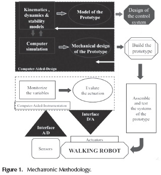
Kinematics, Dynamics and Stability Models: this module includes the theoretical part of the prototype design. In the particular case of a mechanical system, the dynamics and cinematic of the system are considered. This block concentrates the formal part of the whole system, where the physical laws or the equations that take part on the different players that integrate the project are analyzed.
Computer Simulation: the simulation part corresponds to the initial efforts to integrate the various elements of the design of the control system, which is important for the development of block dynamics and kinematics stability; these are developed at the same time, while considering some of the physical system characteristics. In addition, in this section some of the hypotheses can be verified by making use of a simulator in order to obtain partial results that indicate correct progress. In this stage, a clarification is required on the development of the project; the designer should make use of the computational tools that help in the development of the global project. However, it is common to misuse computational tools, since some students incorrectly expect the simulator to solve the problem completely.
Model of the Prototype: This part develops the mathematical model and prototype which integrates the main areas involved in its conformation. Obtaining a model will allow us to analyze from several views the result and performance of the prototype, and it will also reduce the development time. It is important to have an appropriate model for the application that is under development.
Mechanical Design of the Prototype: This section has to deal with the structural design of the project. This has to be supported by the analysis of the systems, specifically by the studies of efforts by finite element analysis, the configuration according to the case, and the development of the project requirements.
Design the Control System: In order to design a control system it is important to have a good mathematical model of it. In this stage, the relevant characteristics can be observed for the proposal of the control law to fit its needs, in such way that the conditions of the transient responses to the system, the stability and controllability conditions are taken into account. Once the analysis of this section is performed, it is proposed to build a control scheme and the simulation is carried out. Only then, the results are evaluated. In this part, the known techniques of design of control jointly with the obtained model, part of the simulation, and some characteristics of the prototype design which helps to determine already some practical parameters are used.
Build the Prototype: Once the models, the simulation, the structural design and the control system are analyzed and verified, it is recommendable to continue building the prototype, integrating each described part with the aim of having most of the required characteristics at the end of the first version the prototype. Certain deviations or characteristics out of range It may occur, but, as Figure 1 shows, in case that this happens, students can return to the block of theory development and simulation.
Assemble and Test the Systems of the Prototype: In this part of the methodology, the verification test of the system is achieved by the development specifications. These have to comply with the requirements; in case of no fulfillment, students return to the formal part were the current information can be corrected and redesigned.
Sensor and Actuators: This is the part where the interaction with the environment of the project or prototype to develop takes place. Therefore, we add the part of the sensors to capture the information from the environment and the actuators that help to act over the environment.
A/D and D/A Interfaces: The conversion interface from analog to digital signals is made by transforming the analog signals that can be captured from the environment and that can be processed in a digital system. On the other hand, if taking action over a system or analog signal is required, the information usually comes from a digital system.
Computer Aided Instrumentation: Once everything is correctly operating, there are two main parts that can be evaluated. The first is the behavior of the development, where it is necessary to monitor the relevant variables of the process and perform an evaluation or elaborate statistics. The other part is the evaluation of the applied models and their improvement.
In the second model an evolution and a generalization were performed. This was organized, as well, in several functional blocks as shown in Figure 2.
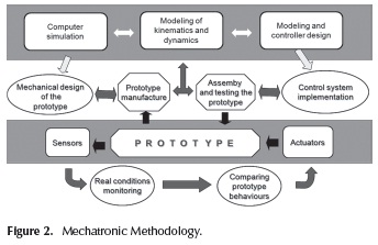
As a result, the methodology of mechatronics projects is based on four stages.
Modeling and computer simulation stage: In this stage, the cinematic, dynamic and control system modeling of the components of the device takes place. Computer simulations perform the validation of the proposed models with the aim of evaluating the modeling equations and of analyzing its results.
Manufacture and assembly stage: In this stage the plans for the manufacture of the prototype pieces are designed. Several prototype components are bought and several pieces are manufactured. Next, the elements of the prototype are assembled and finally the prototype subsystems are tested.
Prototype stage: The different systems that integrate the whole prototype are adjusted and tested. These are redesigned if necessary, and several statistical operation tests are performed to achieve a certain level of confidence. At this stage the technical specifications of the prototype are verified.
Comparison stage: In this stage the comparison between the mathematical model and the real performance of the operating prototype is carried out. This generates new knowledge, leading to improvements in future prototypes, depending on the improvement criterions (weight, speed, precision and strength, among other characteristics).
Two Cases of Study
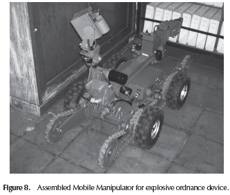
Mobile Manipulator
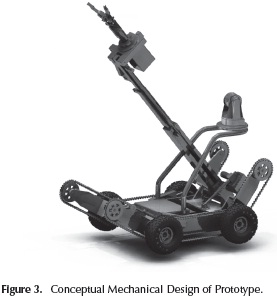
A mobile manipulator with 12 degrees of freedom was developed in order to perform some operations on objects, where it is important to mention the high complexity of the dynamic and kinematic model of the mechatronic system carried out as part of the computer simulation. This project was made by a Ph.D. student and a collaboration group. Figure 3 shows the Conceptual design of the mobile manipulator:
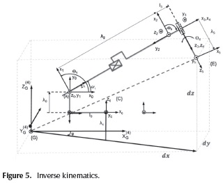
Modeling and computer simulation: Based on the homogenous transformation graph and the kinematic interactions table is the forward kinematic developed, being with the transformation A_C, which is the coordinate "C" and from these are depicted the transformations of the wheels, the lift arms and the manipulator, considering the end effector "E" with the load "Eu". This is shown in Figures 4 and 5.
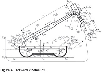
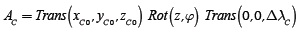
The homogenous transformation of the mobile platform is:
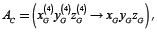
where
and its parameters are:
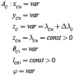
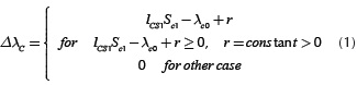
The increment of λc depends on the following relation:
Then, the transformation of the local coordinate is obtained, GTC = AC and so are the transformations of the right and left wheels, GTR = AC AR y GTL = AC AL.
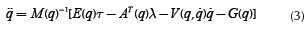
The dynamic model was done using Lagrange's computational algorithm, based on the homogenous transformations. We developed the computer simulation using the letter L to describe each step. L1 is the description of each link of the interaction table HTG. L2 is the classification of the homogeneous transformation. L3 is the determination of the primary matrices of Uij. L4 is the determination of the secondary matrix Uijk. L5 describes the pseudo inertial matrices of each link. L6 is the inertia matrix M(q) = [dij]. L7 is the determination of the Coriollis and centrifuge force parameters h.ikm. L8 is the determination of the Coriollis and centrifuge forces. L9 is the determination of the gravity matrix G(q) = [ci]T and L10 is the dynamic equation V(q, ) = [h.i]T.

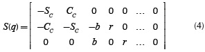
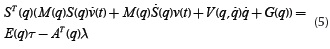
The two columns from S(q) are the null space from A(q) and are lineal independent. It could present as the lineal combination of two columns from S(q). = S(q)v. Deriving is:  = S(q)
 (t) + Ṡ(q)v(t) and substituting in the Equation (4), Equations 5 and 6 result.

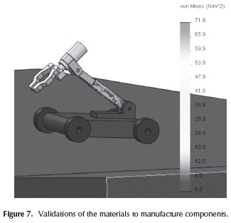
Manufacture and Assembly: Most components were manufactured in 7075 T6 aluminum alloy: AISI 4140 steel alloy and SAE 62 bronze alloy; analyzed and proposed after the Finite Element simulations, they were built by a Computer Numeric Control Machine. They used the G code generated by Solid Works to crate the pieces of the end effector (for the last course a gripper was performed). Other important developments of assembly were the electrical and the electronic stages. All of the electrical devices were calculated and assembled.
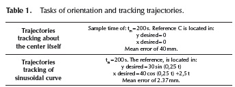
Comparison and Validation Stage: Subsequently, the behavior of the mobile manipulator was simulated using Equation (6), from which the respective errors of each area were obtained as shown in Table 1; in this same sense Figure 7 presents the validation of materials proposed to manufacture components.
Assessment of the Project: Finally the comparison of errors of the simulations and real experimentation of 3 tasks was presented. For each task, 30 tests were carried out, (the kinematic modeling of the robot is validated according to these tests).
Manipulador
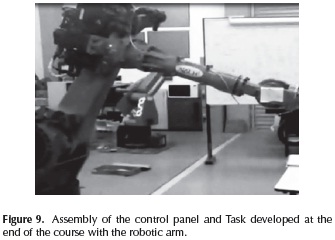
A six-degree-of-freedom Industrial robotic arm was put into operation for a group of six undergraduate automation students. The challenge of this final project was the execution of a movement task. This work was required to fulfill two courses: Servo Systems and Manufacturing Engineering and Robotics. They used the methodology provided in this paper as follows:
Modeling and computer simulation: The first step of the project consists on modeling the mechanical parts under specific requirements. Since the mechanic part of the robot is already designed, students are committed to accomplish the end-effector mechanism. In their Manufacturing course, they learn how to do it by means of Solid Works. Besides, they calculate the motion profiles such as velocity and position in Servo Systems. In the Robotics course students calculate the kinematics of the robot by using Matlab.
Manufacture and Assembly: Regarding the manufacture of the aluminum parts, they were accomplished by a Computer Numeric Control Milling Machine. They used the G code generated by Solid Works to crate the pieces of the end effector (for the last course a gripper was performed). Two other important developments of assembly were the electrical and electronic stages. All of the electrical devices were calculated and assembled.
Computer Assisted Design for the control stage was used; this is shown in Figure 9. Six servo drives were interconnected by a motion controller card. According to (Gómez-Espinosa et al. 2014; Rodríguez-Reséndiz et al. 2011) the assembly of the system can help e students to discuss issues about troubleshooting. Because this project was developed in the final block of the undergraduate program, the teams have the sufficient skills to manage topics required such as: Electrical Machines, Advanced Programming, and Electrical Installations; to mention, a few (Rodríguez-Reséndiz. Et al. 2012) Figure 9 shows the final assembled project. Comparison and Validation Stage: certain routines are tested with the robot, permitting to verify the built system. Therefore, mathematic equations are compiled in software.
The generated algorithms are downloaded to the motion controller which performs the motion profiles and sends the signals to the servo amplifiers. Finally, movements in the motor can be observed because of the signal provided by the servo drive.
Assessment of the Project: Currently, the undergraduate program advances towards ABET certification (Olds and Miller 2005). Eventually, skill criteria will be evaluated in the project, so that it may be attractive to other similar programs that want to be accredited. Some of these skills are:
Results
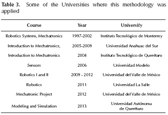
The proposed methodology has been the result of several years of experience in the Mechatronics teaching area and in the development of projects. In Table 3 a summary of some of the courses where the proposed methodology was utilized as part of its content is presented. In each one of the courses, as usual, different conditions that contributed to the enrichment of the proposal exposed in this article are presented.
When the methodology was introduced to the students at the first engineering courses, they could generate an overview of the projects elaboration and the structure of the study plan. In Figure 1, we can observe that the blocks along the professional career will become the name of the courses. During the project development courses, the participants structured the solution and participated in the beginning of the project to be developed, highlighting and giving an especial place to courses and areas that will help in the development and integration of the project.
The development of the methodology was applied at first time in the development of walking robots. Some results of the work are published (Vargas 1998; Vargas-Soto Emilio 2012) at the different stages that the methodology offers.
Another level of application was given by taking the methodology as main support at several courses and certifications. One of the courses was offered to the Faculty of Sonora University. And other significant example was a certification for the department of development and research of Takata Company, where the aim was focused in the development of new products and projects. From these experiences, good results were obtained. At universities, the course was implemented previous to the opening of the bachelor major. Regarding the company, the most interesting part was the development of products in a shorter period of time and under a specific structure. In different ways, the methodology contributes to the formation of professionals in mechatronics.
In the first case of study, the project was practically developed in all of its stages. Here, the model development in which the three subsystems are involved was presented. In the same way, the mechanics, all the simulation part and the control systems were developed. In the second case of study this was directly applied in the teaching of several courses at bachelors with different majors in Mechatronics, Instrumentation or Electronics.
On the other hand, this methodology was also used in the development of applied technological projects. To cite some examples, it was used in a meat electro-stimulating device and in the development and vibration analysis in the building of acoustic guitars (Gorrostieta et al. 2012). In this projects, the methodology was under validation and evaluation, given that there is no trivial relationship with the original proposed areas.
Conclusions
This paper shows a series of collaborative experiences in academic projects. These projects were carried out using a methodology that has been proven effective to generate mechatronics technology. Additionally, the participation of students in research and development projects allows highly qualified academic training in Mechatronics Engineering, so that the knowledge and skills achieved in the projects will allow participants to succeed in their future development projects and research.
As an example of the effectiveness of the presented methodology, the paper describes some of the projects undertaken by the authors. The successful conclusion of each project in a relatively short time, gives us confidence to continue working with the described methodology.
References
Aviles, L. Pedraza J, Gorrostieta, E. and Ramos, J. (2010) New approach to modeling and simulation methodology for the mechatronic design of iedd-unmanned wheeled mobile manipulator, in Electronics, Robotics and Automotive Mechanics Conference (CERMA). 295 -301. [ Links ]
Comerford, R. Mecha...what? [mechatronics], (1994) Spectrum, IEEE, vol. 31, no. 8, 46 -49. [ Links ]
Gómez-Espinosa, A. Lafuente-Ramón, C. Rebollar-Huerta, M.A. Hernández-Maldonado, E. H Olguín-Callejas, H. Jiménez-Hernández, E.A. Rivas-Araiza, J. Rodríguez-Reséndiz, (2014) Design and Construction of a Didactic 3-DOF Parallel Links Robot Station with a 1-DOF Gripper, J Appl Res Technol, vol. 12, no. 1, 435-443. DOI: 10.1016/S1665-6423(14)71624-4. [ Links ]
Gorrostieta-Hurtado, Efren. Pedraza-Ortega, Jesus-Carlos. Ramos-Arreguin, Juan-Manuel. Sotomayor-Olmedo, Artemio. and Perez-Meneses, Joaquín. (2012) Vibration analysis in the design and construction of an acoustic guitar, International Journal of Physical Sciences Vol. 7(13), 1986 - 1997. [ Links ]
Gorrostieta, E. Ramos, J. M., and Pedraza, J. C. (2007) A mechatronics methodology, In New Trends in Electronics Technology, 84 -92. [ Links ]
Habash, R. and Suurtamm, R. (2010) Engaging high school and engineering students: A multifaceted outreach program based on a mechatronics platform, Education, IEEE Transactions on, vol. 53, no. 1. 136 -143. DOI: 10.1109/TE.2009.2025659. [ Links ]
Hsu, T. R. Mechatronics. (1997) an overview, Components, Packaging, and Manufacturing Technology, Part C, IEEE Transactions on, vol. 20, no. 1, 4 -7. DOI: 10.1109/3476.585138. [ Links ]
Isermann, R. (1996) Modeling and design methodology for mechatronic systems, Mechatronics IEEE/ASME Transactions on, vol. 1, no. 1, 16-28. [ Links ]
Secchi, C, Bonfe, M. and Fantuzzi, C. (2007) On the use of uml for modeling mechatronic systems, Automation Science and Engineering, IEEE Transactions on, vol. 4, no. 1, 105 -113. [ Links ]
Rodríguez-Reséndiz, J. Rivas-Araiza, E. A. Herrera-Ruiz, G.(2011) Adjustable Speed Drive Project for Teaching a Servo Systems Course Laboratory, IEEE Trans. on Education, vol. 54, no. 4, 657-666. DOI: 10.1109/TE.201 1.2106213. [ Links ]
Rodríguez-Reséndiz, J. Mendoza-Mondragón, F. Gómez-Loenzo, R. A.. Martínez-Hernandez, M. A (2012) An approach to motion control applications based on advanced programmable devices, Int. J. Elec. Eng. Edu.,vol. 49, 243-259. DOI: 10.7227/IJEEE.49.3.5. [ Links ]
Tutunji, T. Saleem, A. and Rabbo, S. (2009) An undergraduate mechatronics project class at philadelphia university, jordan: Methodology and experience, Education, IEEE Transactions on, vol. 52, no. 3, 365 -374. DOI: 10.1109/te.2008.930088. [ Links ]
Olds, B. Moskal, M. and Miller, R. L. (2005) Assessment in engineering education: Evolution, approaches, and future collaborations, J. Eng. Educ., 94, 13-25. DOI: /10.1002/j.2168-9830.2005.tb00826.x. [ Links ]
Vargas-Soto, E. (2008) Teaching mechatronics with real projects and integral, The Clute Institute For Academic Research Promoting and Publishing Quality Scientific Research, no. 1, 46 -49. [ Links ]
Vargas, E. (1998) A New Real-time Control Method for Free Locomotion in a Walking Robot, International Journal of Computer Application in Technology, Vol. 11 Nos.1/2,. 77-83. [ Links ]
Vargas, E. and Rodriquez, W. (2004) Mechatronics design of automatic machine to manipulate sheet of cardboard, in The International Congress on Mechatronis and Robotics MECH& ROB2004. [ Links ]
Vargas-Soto, Emilio. Gorrostieta, E. Sotomayor-Olmedo, Artemio. Ramos-Arreguin, Juan-Manuel. and Tovar-Arriaga, Saul. (2012) Design of fuzzy algorithms locomotion for six legged walking robot, International Journal of Physical Sciences, Vol. 7(11), 1811 - 1819. [ Links ]
Velinsky, S.A. and Gardner, J.F. (2000) Kinematics of mobile manipulators and implications for design, Journal of Robotics Systems, 309-320. [ Links ]
